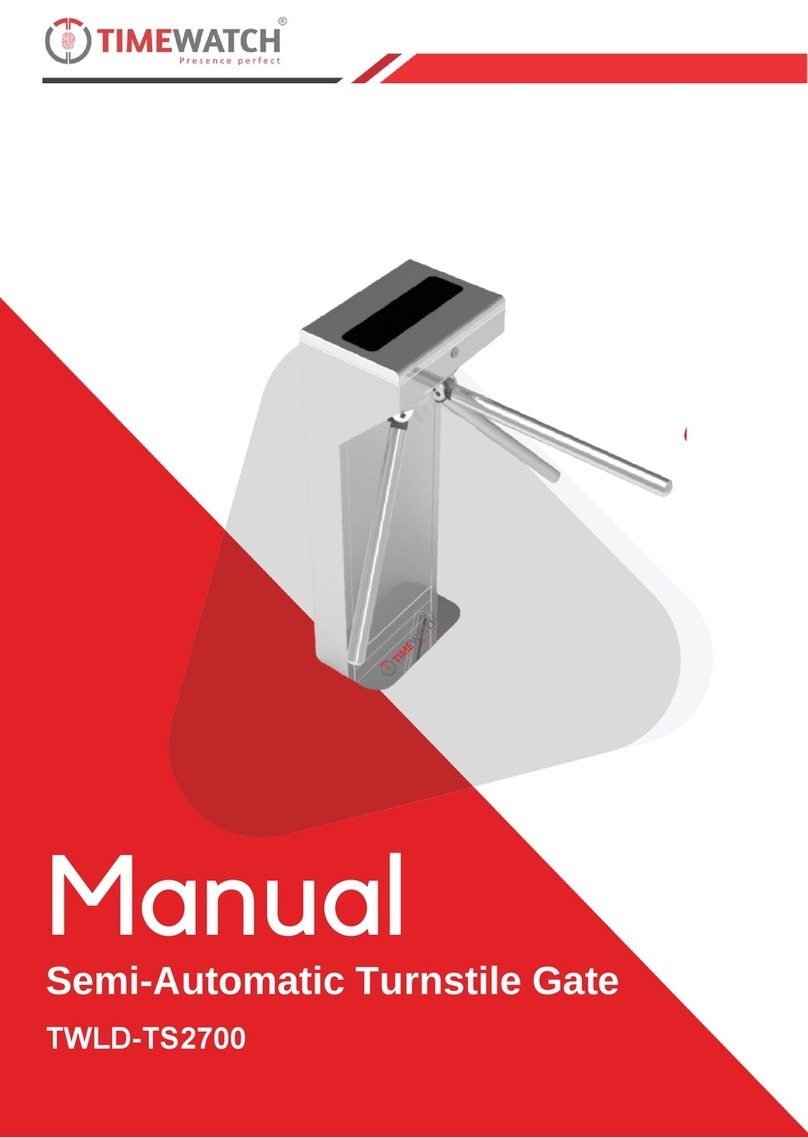
Magnetic Autocontrol MPS-122 User manual

Operating Instructions
Swing Door
MPS-122
Doc-ID: 5817,0011EN
Version: 04

Swing Door MPS-122
Contents
5817,0011EN / Version 04 3
Contents
1General....................................................................................7
1.1 Information regarding the operating instructions ...........7
1.2 Pictogram explanation ...................................................8
1.3 Limitation of liability........................................................9
1.4 Copyright protection.......................................................9
1.5 Scope of delivery .........................................................10
1.6 Warranty ......................................................................10
1.7 Disclaimer ....................................................................10
1.8 Customer service .........................................................11
1.9 EC-Declarations of conformity .....................................11
1.10 Environmental protection .............................................11
2Safety ....................................................................................12
2.1 Intended use ................................................................12
2.2 Operator's Responsibility .............................................13
2.3 Changes and modifications .........................................13
2.4 Specialists and operating personnel............................14
2.4.1 Requirements ...............................................14
2.5 Personal protective equipment ....................................15
2.6 Occupational safety and special dangers....................15
2.6.1 Danger pictograms on
the pedestrian barrier MPS-122 ...................15
2.6.2 Hazard notes and occupational safety .........16
3Technical data ......................................................................19
3.1 Dimensions ..................................................................19
3.1.1 Swing door in bracket version ......................19
3.1.2 Swing door in wing version...........................20
3.2 Electrical connection....................................................20
3.3 Operating conditions....................................................21
3.4 Weight..........................................................................21
3.5 Performance data ........................................................21
4Design and function.............................................................22
4.1 Design..........................................................................22
4.2 Definition left and right swing door ..............................23
4.3 Function .......................................................................23
5Transport, mounting and installation ................................24
5.1 Safety...........................................................................24
5.2 Requirements for mounting and installation ................26
5.3 Foundation and empty conduits...................................26
5.3.1 Foundation plan, fixing and drilling plan.......27

Swing Door MPS-122
Contents
45817,0011EN / Version 04
5.4 Mounting the swing door............................................. 29
5.4.1 Design.......................................................... 29
5.4.2 Mounting the swing door on the foundation 30
6Electrical connection .......................................................... 33
6.1 Safety .......................................................................... 33
6.2 Installing electrical protective devices......................... 34
6.3 Performing electrical connections ............................... 35
6.4 Connecting control lines to MBC-111 ......................... 37
6.4.1 Digital inputs ................................................ 37
6.4.2 Relay outputs............................................... 38
7Mechanical settings and final installation ........................ 39
7.1 Adjusting the mechanical end stops ........................... 39
7.1.1 Aligning outer tube....................................... 39
7.1.2 Adjusting the mechanical end stops ............ 40
7.2 Mounting locking element ........................................... 41
7.2.1 Mounting brackets ....................................... 41
7.2.2 Mounting wings............................................ 42
8Commissioning and settings ............................................. 44
8.1 Safety .......................................................................... 44
8.2 Switching the swing door on and off ........................... 45
8.3 Initial commissioning ................................................... 46
8.4 Setting the home position and hold-open time
via button..................................................................... 47
8.4.1 Setting the home position ............................ 47
8.4.2 Setting the hold-open time........................... 48
9Function description........................................................... 50
9.1 Power-off state ............................................................ 50
9.2 Start-up routine ........................................................... 50
9.3 Homing........................................................................ 50
9.4 Regular movement process ........................................ 51
9.5 Special cases within motion sequence ....................... 52
9.5.1 Obstacle recognition during the movement. 52
9.5.2 Turning back during the movement ............. 52
9.5.3 Attempted vandalism ................................... 53
9.5.4 Emergency................................................... 53
10 Setting swing door parameters – "MPS-Diag" ................. 54
10.1 Driver installation under Windows 7............................ 55
10.1.1 Automatic driver installation
via setup assistant ....................................... 55
10.1.2 Manual driver installation............................. 56
10.1.3 Entering the port number in the programme
"MPS-Diag".................................................. 57
Swing Door MPS-122
Contents
5817,0011EN / Version 04 5
10.2 Connecting laptop to control device MB-111...............58
10.3 Using the MPS-Diag programme.................................59
10.4 Function and parameter settings .................................60
10.4.1 Version left / right .........................................60
10.4.2 Brake activated / not activated .....................61
10.4.3 Select size of the locking element................62
10.4.4 Select reset source.......................................62
10.4.5 Stalled behaviour (Behaviour when
obstruction detected)....................................62
10.4.6 Set hold-open time .......................................63
10.4.7 Set speed .....................................................63
10.4.8 Heating active while standing.......................63
10.4.9 Teaching the three possible positions..........64
10.4.10 Reset all parameters to factory settings.......66
10.5 Firmware download .....................................................67
10.5.1 Firmware download using a ".mcp file" ........69
10.5.2 Firmware download using an ".s file" ...........69
10.6 Download between MBC-111 and MMC-120 ..............71
10.7 Reading errors .............................................................72
10.8 Status request..............................................................73
11 Cleaning and maintenance .................................................74
11.1 Safety ......................................................................74
11.2 Cleaning ......................................................................76
11.3 Maintenance schedule.................................................77
12 Malfunctions .........................................................................78
12.1 Safety ......................................................................78
12.2 Error codes on the logic controller MBC-111...............80
12.3 CAN bus addressing and termination..........................82
13 Spare parts ...........................................................................83
14 Decommissioning, disassembly and disposal .................84
15 EC-Declarations of conformity ...........................................85
16 Appendix...............................................................................86
16.1 Electric circuit diagram.................................................86
Index..............................................................................................87

Swing Door MPS-122
General
5817,0011EN / Version 04 7
1 General
1.1 Information regarding the operating instructions
These operating instructions provide important information on how
to deal with the MAGNETIC swing door MPS-122. Prerequisite for
safe working is the observance of all specified safety notes and
instructions.
In addition, the local accident prevention regulations valid at the
pedestrian barrier's area of application and general safety
regulations have to be complied with.
Carefully read the operating instructions before starting any work!
They are a product component and must be kept well accessible to
the personnel at all times.
When passing the pedestrian barrier on to third parties, the
operating instructions must also be handed over.
Components from other suppliers may have their own safety
regulations and instructions for use. These must also be observed.

Swing Door MPS-122
General
85817,0011EN / Version 04
1.2 Pictogram explanation
Warning notes Warning notes are characterised by pictograms in these operating
instructions. The warning notes are followed by signal words
expressing the scale of the hazard.
It is absolutely essential to observe the notes and to proceed with
caution in order to prevent accidents as well as bodily injuries and
property damage.
DANGER
The signal word DANGER points to an immediately
dangerous situation, which leads to death or
severe injuries if it is not avoided.
WARNING
The signal word WARNING points to a potentially
dangerous situation, which can lead to death or
severe injuries if it is not avoided.
CAUTION
The signal word CAUTION points to a potentially
dangerous situation, which can lead to minor
injuries if it is not avoided.
NOTICE
The signal word NOTICE points to a potentially
harmful situation, which can lead to property
damage if it is not avoided.
Hints and recommendations
NOTE!
… highlights useful hints and recommendations as
well as information for an efficient and trouble-free
operation.

Swing Door MPS-122
General
5817,0011EN / Version 04 9
1.3 Limitation of liability
All specifications and notes in these operating instructions were
compiled with consideration to the valid standards and regulations,
the state of the art as well as to our long-standing knowledge and
experience.
The manufacturer is not liable for damage caused by:
Non-observance of the operating instructions
Improper use
Deployment of non-trained personnel
Arbitrary modifications
Technical changes
Use of non-approved spare and wear parts.
The actual scope of supply may differ from the explanations and
illustrations described in this manual in case of special designs, if
additional order options are made use of, or due to latest technical
changes.
1.4 Copyright protection
Surrendering the operating instructions to third parties without
written permission of the manufacturer is not permitted.
Content details, texts, drawings, pictures and other illustrations are
protected by copyright and are subject to industrial property rights.
Any improper use shall be liable to prosecution.
Any type and form of duplication – also of extracts – as well as the
exploitation and/or communication of the contents are not
permitted without the manufacturer's written declaration of consent.

Swing Door MPS-122
General
10 5817,0011EN / Version 04
1.5 Scope of delivery
The scope of delivery comprises:
1 x Swing door with integrated drive and integrated
control units MBC and MMC
1 x Locking element
1 x USB-extension
1 x Drilling jig
1 x Fastening kit (only within Europe)
1 x Software on data carrier
Supplied documentation:
1 x Operating instructions
1 x Electric circuit diagram
Optionally available:
MPS-Diag Windows software for setting functions and
parameters and for error diagnosis
1.6 Warranty
Subject to the condition that the operating instructions are
observed, and that no inadmissible operations are carried out on
the technical equipment, and that the installation has suffered no
mechanical damage, MAGNETIC grants a warranty on all
mechanical and electrical components of the extent as stated in its
standard terms of sales and delivery or as contractually agreed in
writing.
1.7 Disclaimer
MAGNETIC expressly disclaims all implied and statutory
warranties, including but not limited to, the implied warranties of
merchantability and fitness for a particular purpose with respect to
the product and the statutory warranty of non-infringement of third
party rights set forth in section 2312(3) of the uniform commercial
code.

Swing Door MPS-122
General
5817,0011EN / Version 04 11
1.8 Customer service
Your vendor is available to you for technical information
For the address, see invoice, delivery note or the reverse of these
instructions.
NOTE!
In order to enable fast handling note the data of the
type plate such as type code, serial number, etc.
before calling.
1.9 EC-Declarations of conformity
EC-Declarations of conformity (pursuant to EC Machinery Directive
2006/42/EC, Annex II) refer to page 85.
1.10 Environmental protection
NOTICE
Improper disposal!
In case of improper disposal of the pedestrian
barrier or components, damage to the environment
may result.
– Observe the local and national laws and
directives.
– Disassemble pedestrian barrier according to
resources. Sort resources and supply them to
recycling.

Swing Door MPS-122
Safety
12 5817,0011EN / Version 04
2 Safety
2.1 Intended use
The MAGNETIC pedestrian barrier MPS is intended exclusively for
managing the admission in to areas with restricted access.
In general, the swing door is integrated in the fence and gate
systems.
The pedestrian barrier is intended for passage of persons who can
pass the pedestrian barrier safely, quickly and without help. For
persons who cannot pass the pedestrian barrier safely, quickly or
without help, such as little children, older persons or persons with
impairments, separate access options must be provided.
The integrated MAGNETIC control units MBC and MMC are
intended exclusively for controlling the MAGNETIC pedestrian
barrier MPS.
WARNING
Non-intended use!
Any use of the pedestrian barriers other than
intended and/or in a different manner can cause
hazardous situations.
– Only use the pedestrian barrier and the control
units for the intended use.
– All specifications in these operating instructions
have to be strictly complied with.
Any types of claims due to damage arising from improper use are
excluded. The operator alone shall be responsible for any damage
arising from improper use.

Swing Door MPS-122
Safety
5817,0011EN / Version 04 13
2.2 Operator's Responsibility
The operator must comply with the statutory obligations regarding
work safety.
In addition to the work safety notes in these operating instructions,
the safety, accident prevention and environmental provisions
applicable for the area the pedestrian barrier is used in must be
complied with.
In particular, the operator must:
gather information on applicable work protection provisions.
determine additional danger in a danger analysis.
implement the required code of conduct for operation of the
pedestrian barrier on site in operating instructions.
regularly verify throughout the pedestrian barrier's time of use
that the operating instructions drawn up by him comply with the
current state of the regulations.
adapt the operating instructions to any new provisions,
standards and usage conditions - where required.
clearly determine the responsibilities for installation, operation,
maintenance and cleaning of the pedestrian barrier.
ensure that all employees that are working at or with the
pedestrian barrier have read and understood the operating
instructions.
Furthermore, the operator must train personnel regarding the
use of the pedestrian barrier at regular intervals and provide
information on possible dangers.
Furthermore, the operator is responsible for:
keeping the pedestrian barrier in perfect technical order and
condition at all times.
maintaining the pedestrian barrier according to the maintenance
intervals and performing the safety inspections as stipulated.
checking all protective facilities for completeness and proper
function at regular intervals.
The operator is also responsible that the danger area of the
pedestrian barrier cannot be accessed by any unauthorised
persons, and in particular not by children, under any
circumstances.
2.3 Changes and modifications
Changes and modifications of the pedestrian barrier can cause
unforeseen danger.
A written authorisation of the manufacturer is absolutely required
before executing any technical changes and modifications at the
pedestrian barrier, the control unit or the control program.

Swing Door MPS-122
Safety
14 5817,0011EN / Version 04
2.4 Specialists and operating personnel
2.4.1 Requirements
WARNING
Inadequate qualification!
Improper handling can lead to considerable bodily
injuries and property damage.
– Activities musst only carried out by the
individuals designated for that purpose.
The operating instructions specify the following qualification
requirements for the different fields of activity:
Instructed people
have been instructed during instructions provided by the
operator with regard to the work assigned to them and possible
hazards arising from improper conduct.
Specialised staff
are able, due to their technical training, knowledge and
experience as well as their knowledge of the pertinent
regulations are able to carry out work assigned to them
independently and to recognise potential hazards.
Electrical specialists
are able, due to their technical training, knowledge and
experiences as well as knowledge of the relevant standards
and regulations, to execute tasks on electrical systems and to
independently recognise possible hazards.
In Germany, the electrical specialist must comply with the
provisions of accident prevention regulation BGV A3 (e.g.
master electrical fitter). Appropriate regulations apply in other
countries. The regulations valid there must be observed.
It must be expected that only those people are deployed who carry
out their work reliably. People, whose ability to respond is affected,
e.g. by drugs, alcohol or medicines, must not be used.
Furthermore, the age and profession-specific regulations valid at
the operating location must be observed when selecting personnel.

Swing Door MPS-122
Safety
5817,0011EN / Version 04 15
2.5 Personal protective equipment
It is necessary to wear personal protective equipment when
dealing with the machine so as to minimise health hazards.
Before carrying out any work, properly put on the necessary
protective equipment such as work clothes, protective gloves,
safety shoes and wear during work.
2.6 Occupational safety and special dangers
The remaining risks resulting from the hazard analysis are
specified in the following section.
Observe the safety notes listed here and the warning notes
mentioned in the other chapters of these instructions to reduce
health hazards and to avoid dangerous situations.
2.6.1 Danger pictograms on the pedestrian barrier MPS-122
The relevant dangerous areas on the pedestrian barriers can be
identified by the following pictograms:
Electric voltage
DANGER
Mortal danger by electric voltage!
... indicates life threatening situations caused by
electric voltage. Non-observance of the safety
instructions causes severe injuries or death.
Necessary work may only be carried out by an
electrical specialist.
This pictogram is fixed on the following component:
– Cover sheet at the edge profile.
Danger of crushing
WARNING
Danger of crushing!
… indicates the presence of components and items
moving towards each other. Non-observance of the
safety instructions can lead to severe injuries.
This pictogram is fixed on the following component:
– Edge profile, below the mechanic stops.

Swing Door MPS-122
Safety
16 5817,0011EN / Version 04
2.6.2 Hazard notes and occupational safety
For your own safety and for the protection of the pedestrian barrier,
the following information must be observed and complied with:
Electric voltage
DANGER
Mortal danger by electric voltage!
Touching live parts can be lethal.
Damage to the insulation or to individual
components can be lethal.
– Switch off the power supply immediately in case
of damage to the insulation and arrange repair.
– Only electrical specialists may carry out work on
the electrical system.
– Switch off power supply and secure against
reactivation before performing any work. Test
for absence of voltage!
– Never bypass or deactivate fuses.
– When replacing fuses observe the correct
amperage specification.
– Keep moisture and dust away from live parts.
Moisture or dust may cause a short circuit.
Electric voltage –
missing safety installations
DANGER
Mortal danger by electric voltage!
The safety installations that are required according
to regional and local regulations must be provided
by the customer. Usually these are:
– Residual current device (RCD)
– Circuit-breaker
– Lockable 2-pole main switch according to
EN 60947-3.

Swing Door MPS-122
Safety
5817,0011EN / Version 04 17
Improper transport
WARNING
Danger by falling down or tilting of a pedestrian
barrier!
The weight of the pedestrian barrier of heavy parts
of it can seriously injure a person and cause
serious crushing!
– Have all transport work performed by specialists
only.
– Depending on the dead weight and size of the
components, use a pallet on which the
pedestrian barrier can be moved by means of a
forklift.
– For lifting a pedestrian barrier, use suitable
lifting gear that is designed for the weight of the
pedestrian barrier.
– Lifting and carrying the pedestrian barrier or
heavy parts of it from the pallet should be done
by a minimum of two people.
Heavy weight
WARNING
Lifting heavy loads!
The weight of heavy objects can severely injure a
person's back or supportive system.
– Lifting and carrying the pedestrian barrier and
heavy components should be done by a
minimum of two people.
Insufficient fixing
WARNING
Insufficient fixing!
Insufficient fixing at the pedestrian barrier or any
single component can severely injure a person and
cause severe crushing.
– Only qualified and skilled personnel are allowed
to assemble the pedestrian barrier and the
appropriate components.
– Before operation of the pedestrian barrier,
ensure the firm fixing of the tie anchors.
– Check the firm fixing of all screws according to
maintenance schedule.

Swing Door MPS-122
Safety
18 5817,0011EN / Version 04
Inadmissible operation
WARNING
Inadmissible operation!
An inadmissible operation can cause severe
injuries.
– Before operating the pedestrian barriers check
all electrical and mechanical functions.
Sharp edges and spiky corners
CAUTION
Sharp edges and spiky corners!
Sharp edges and spiky corners can cause skin
abrasions and cuts.
– Work carefully near to sharp edges and spiky
corners.
– In case of doubt wear protective gloves.
Signposting
CAUTION
Unrecognisable labels and signs!
Labels and signs can become dirty or
unrecognisable in the course of time.
– Always keep safety, warning and operating
notes in a well readable condition.
– Immediately renew damaged or unrecognisable
signs or labels.

Swing Door MPS-122
Technical data
5817,0011EN / Version 04 19
3 Technical data
3.1 Dimensions
3.1.1 Swing door in bracket version
5
480
390
30 ∅ 159 D50
B
1000
Mag00274b
A
A
Fig. 1: Dimensions for swing door in bracket version
A Safety distances to avoid crushing
B Total width
D Bracket length, Standard: 1090 mm, max. 1800 mm

Swing Door MPS-122
Technical data
20 5817,0011EN / Version 04
3.1.2 Swing door in wing version
980
821
Mag00571b
X
282
5
50
A
30 ∅ 159
1000
A
800 / 1030 / 1330
200 / 170
Fig. 2: Dimensions for swing door in wing version
A Safety distances to avoid crushing
X Floor distance: 200 mm at wing height 800 mm,
170 mm at wing heights 1030 mm and 1330 mm
3.2 Electrical connection
Designation Unit MPS-122
230 V 50 Hz 1) 115 V 60 Hz 1)
Supply voltage V AC / Hz 110 to 250 / 50 – 60 Hz
Current consumption
MPS in the resting position
A 0.14 0.16
Power consumption
MPS in the resting position
W 12 11
Max. current consumption
MPS in movement
A 0.19 0.29
Max. power consumption
MPS in movement
W 24 25
Starting current (approx. 30 ms) A 1.7 1.7
Control voltage V DC 42
1) The values are without heating. Activate heating via the programme "MPS-Diag". With the heating activated, the
values increase.
Table 1: Electrical connection
Table of contents
Other Magnetic Autocontrol Turnstile manuals

Magnetic Autocontrol
Magnetic Autocontrol MPT 33 User manual

Magnetic Autocontrol
Magnetic Autocontrol MPT-132 User manual

Magnetic Autocontrol
Magnetic Autocontrol MPT-333 User manual

Magnetic Autocontrol
Magnetic Autocontrol MPT-152 User manual

Magnetic Autocontrol
Magnetic Autocontrol MPH 112 User manual

Magnetic Autocontrol
Magnetic Autocontrol MPT-132 User manual