10 Part Number: 9295040 07/17
Installation Section 2
Electrical Service
DANGER
Check all wiring connections, including factory terminals,
before operation. Connections can become loose during
shipment and installation.
nWarning
This appliance must be grounded and all field wiring must
conform to all applicable local and national codes. Refer
to rating plate for proper voltage. It is the responsibility of
the end user to provide the disconnect means to satisfy
the authority having jurisdiction.
VOLTAGE
All electrical work, including wire routing and grounding,
must conform to local, state and national electrical codes.
The following precautions must be observed:
• The equipment must be grounded.
• A separate fuse/circuit breaker must be provided for each
unit.
• Check all green ground screws, cables and wire
connections to verify they are tight before start-up.
GROUND FAULT CIRCUIT INTERRUPTER
Ground Fault Circuit Interrupter (GFCI/GFI) protection is a
system that shuts down the electric circuit (opens it) when it
senses an unexpected loss of power, presumably to ground.
Welbilt does not recommend the use of GFCI/GFI circuit
protection to energize our equipment. If code requires the
use of a GFCI/GFI then you must follow the local code. The
circuit must be dedicated, sized properly and there must
be a panel GFCI/GFI breaker. We do not recommend the
use of GFCI/GFI outlets to energize our equipment as they
are known for more intermittent nuisance trips than panel
breakers.
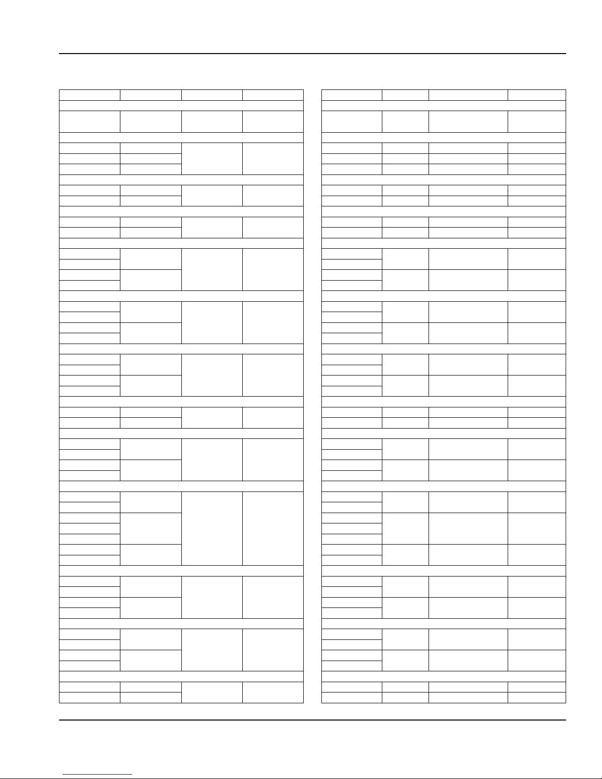
Maximum 10ft (3m) cord with plug.
Model Amps V, Hz, Ph H.P. Nema Plug
Reach-In Dual Temperature
CSDBR1P-SH
CSDTR1P-SH
5.8 115, 60, 1 Ref. 0.20
Frzr. 0.315
5-15P
Reach-In Freezers
CSF1P-S (H) 7.2 115, 60, 1 0.55 5-15P
CSF2P-S (H) 10.0 115, 60, 1 0.68 5-15P
CSF3P-S (H) 14.7 115, 60, 1 (2X)0.55 5-20P
Pass-Thru Freezers
CSFPT1P-S (H) 10.0 115, 60, 1 0.55 5-15P
CSFPT2P-S (H) 14.6 115, 60, 1 (2X)0.55 5-20P
Roll-In Freezers
CSFRI1P-S 10.0 115, 60, 1 0.68 5-15P
CSFRI2P-S TBD 115, 60, 1 (2X)0.55 5-20P
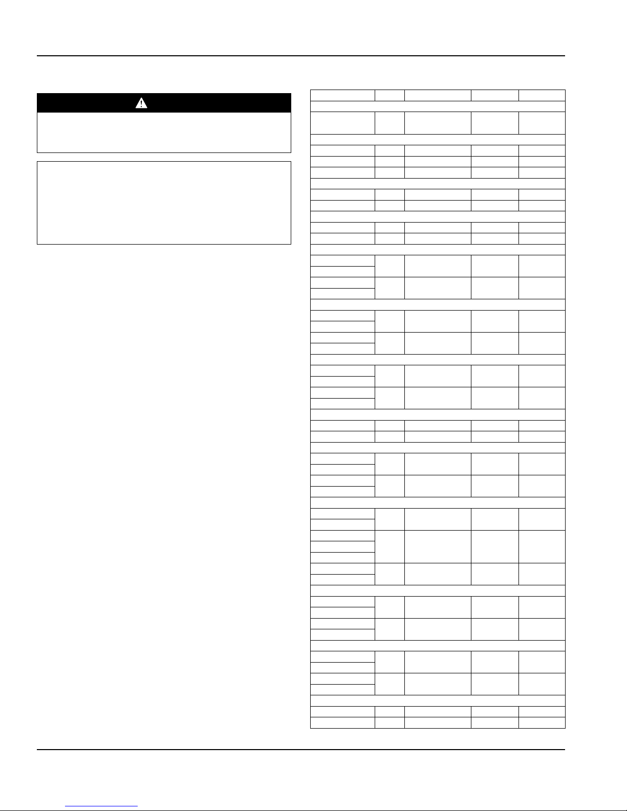
Reach-In Heated Cabinets
CSH1-G (H) 6.0 208-240, 60, 1 NA 6-20P
CSH1-S (H)
CSH2-G (H) 10.5 208-240, 60, 1 NA 6-20P
CSH2-S (H)
Pass-Thru Heated Cabinets
CSHPT1-G (H) 6.0 208-240, 60, 1 NA 6-20P
CSHPT1-S (H)
CSHPT2-G (H) 10.5 208-240, 60, 1 NA 6-20P
CSHPT2-S (H)
Roll-In Heated Cabinets
CSHRI1-G 6.0 208-240, 60, 1 NA 6-20P
CSHRI1-S
CSHRI2-G 10.5 208-240, 60, 1 NA 6-20P
CSHRI2-S
Roll-Thru Heated Cabinets
CSHRT1-S 6.0 208-240, 60, 1 NA 6-20P
CSHRT2-S 10.5 208-240, 60, 1 NA 6-20P
Narrow Reach-In Refrigerators
CSR1NP-G (H) 4.2 115, 60, 1 0.22 5-15P
CSR1NP-S (H)
CSR2NP-G (H) 6.0 115, 60, 1 0.33 5-15P
CSR2NP-S (H)
Reach-In Refrigerators
CSR1P-G (H) 4.2 115, 60, 1 0.22 5-15P
CSR1P-S (H)
CSR2P-G (H)
6.0 115, 60, 1 0.33 5-15PCSR2P-GL
CSR2P-S (H)
CSR3P-G (H) 6.5 115, 60, 1 0.355 5-15P
CSR3P-S (H)
Pass-Thru Refrigerators
CSRPT1P-G (H) 4.5 115, 60, 1 0.22 5-15P
CSRPT1P-S (H)
CSRPT2P-G (H) 6.2 115, 60, 1 0.33 5-15P
CSRPT2P-S (H)
Roll-In Refrigerators
CSRRI1P-G 6.0 115, 60, 1 0.33 5-15P
CSRRI1P-S
CSRRI2P-G 6.2 115, 60, 1 0.355 5-15P
CSRRI2P-S
Roll-Thru Refrigerators
CSRRT1P-S 6.0 115, 60, 1 0.33 5-15P
CSRRT2P-S TBD 115, 60, 1 0.355 5-15P