Delfin LYRA User manual
DELFIN S.r.l. –Via Keplero, 18 C.F. e P.IVA 02528290246
36034 MALO (VI) Italy REG.IMPR.VICENZA N. 186653/1996
Tel.: +39 0445 580688 Fax: +39 0445 580766 R.E.A. N. 237768
e-mail: info@delfin.it http://www.delfin.it Cap. Soc. Є100.000,00 i.v.
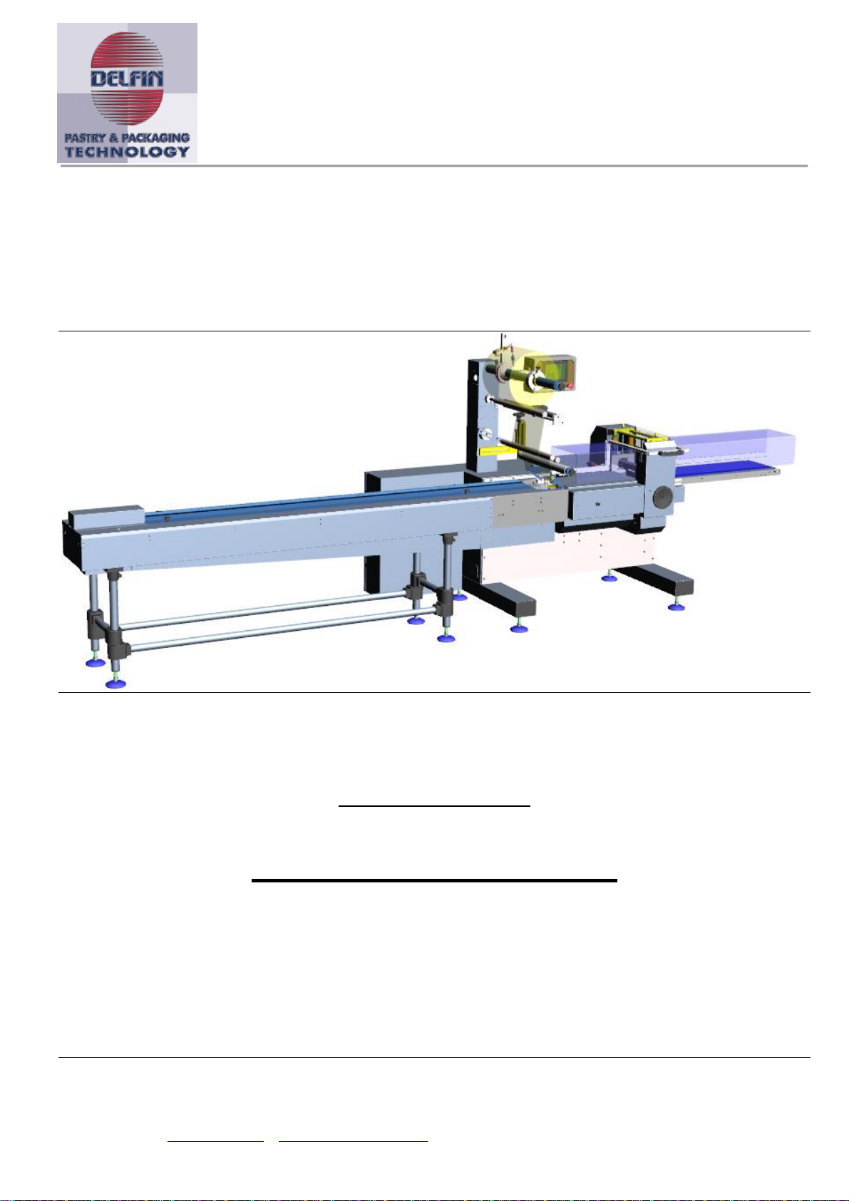
“LYRA”
Order DELFIN:
Year of construction: 2017
Instruction Manual
ORIGINAL INSTRUCTIONS

Pag 2 / 154
Manuale Lyra 600 sx elettr eng
Summary:
1General information ............................................................................ 7
1.1 List of documents ...............................................................................................7
1.2 This instruction manual .......................................................................................7
1.3 Information property ..........................................................................................8
1.4 Meanings and symbols ........................................................................................9
1.5 Identification data of the manufacturer .................................................................9
1.6 Machine identification data ................................................................................ 10
1.7 EC conformity declaration.................................................................................. 10
1.8 Warranty......................................................................................................... 11
1.9 Technical assistance ......................................................................................... 12
1.10 Use of the manual.......................................................................................... 12
2Operators’ safety and protective devices........................................... 14
2.1 Safety requirements ......................................................................................... 14
2.2 Classification of machine operators..................................................................... 14
2.3 Machine work zones.......................................................................................... 17
2.4 Description of the command/control and work stations.......................................... 19
2.5 Designed use and prohibited use ........................................................................ 21
2.6 Protective devices, signs and PPE. ...................................................................... 24
2.7 Residual risks................................................................................................... 34
2.8 General Instructions for safety and prevention ..................................................... 45
3Technical data ................................................................................... 48
4Installation........................................................................................ 50
4.1 Positioning and levelling of the machine .............................................................. 50
4.2 Electrical connection ......................................................................................... 54
4.3 Compressed air treatment group (optional) ......................................................... 55
5Controls............................................................................................. 57
5.1 Touch screen control panel ................................................................................ 57
6Film roll holder shaft and calander assembly .................................... 60
6.1 General instructions.......................................................................................... 60
6.2 Description of the components ........................................................................... 61
6.3 Reel assembly and disassembly.......................................................................... 62
6.4 Film dragging device......................................................................................... 63
6.5 Automatic film junction ..................................................................................... 64
6.6 Film editing ..................................................................................................... 67
7Fin wheel assembly's pulling/sealing set .......................................... 70
7.1 General instructions.......................................................................................... 70
7.2 Description of the components ........................................................................... 71

Pag 3 / 154
Manuale Lyra 600 sx elettr eng
7.3 Adjustment of the fin wheel pressure.................................................................. 72
7.4 Replacement of a resistance/probe ..................................................................... 73
7.5 Adjustments of the motorized reel (optional) ....................................................... 75
8Transverse sealing jaw assembly ...................................................... 77
8.1 General instructions.......................................................................................... 77
8.2 Jaw teeth adjustments ...................................................................................... 78
8.3 Jaw teeth adjustment on a sealing jaw with longitudinal sealing pattern .................. 79
8.4 Jaw teeth adjustment on a sealing jaw with transverse sealing pattern ................... 83
8.5 Assembly and adjustment of the knife ................................................................. 86
8.6 Replacement of the brushes on the slip ring holders .............................................. 87
8.7 Heat adjustment and replacement of the heaters ................................................. 88
9Torque limit (safety clutch) on the sealing jaws (only for mechanical
torque limiter).......................................................................................... 91
11 Bag length adjustment with neutral film (not film registered film), on an
electronic machine ................................................................................... 94
13 Setting to work the photocell group .................................................. 96
14 Adjustment of the bag length with print
‐
registered film (optional) ... 98
15 Infeed conveyor .............................................................................. 101
15.1 General instructions ..................................................................................... 101
15.1 Pusher dismantling and assembly .................................................................. 103
15.2 Pusher support dismantling and assembly....................................................... 104
15.3 Adjustment of the infeed conveyor side guides ................................................ 105
15.4 Infeed conveyor chain tensioning................................................................... 106
16 Forming box adjustments................................................................ 108
16.1 General instructions ..................................................................................... 108
16.2 Fixed forming box ........................................................................................ 109
16.3 Adjustable forming box................................................................................. 109
16.4 Fixed adjustable forming box ........................................................................ 113
17 Discharge belt conveyor .................................................................. 116
17.1 General instructions ..................................................................................... 116
17.2 Maintenance................................................................................................ 117
18 Use and maintenance of machinery ................................................. 120
18.1 Checking efficiency protection devices ............................................................ 120
18.2 Use and Maintenance ................................................................................... 121
18.3 Scheduled maintenance................................................................................ 122
18.4 Replacement of sealing jaw supply wires ........................................................ 123
18.5 Check of belts/chain conditions and tension .................................................... 124
18.6 Periodically lubrication.................................................................................. 125
19 Packaging problems and solutions .................................................. 128
20 Touch Screen panel ......................................................................... 131
20.1 Home page ................................................................................................. 133

Pag 4 / 154
Manuale Lyra 600 sx elettr eng
20.2 Alarm page 1/2 ........................................................................................... 134
20.3 Alarm page 2/2 .......................................................................................... 135
20.4 Temperature control page............................................................................. 136
20.5 Block notes –Setting page 1/2...................................................................... 137
20.6 Block notes –Setting page 2/2...................................................................... 138
20.7 Block notes page ......................................................................................... 139
20.8 Product counter page ................................................................................... 140
20.9 Photocell for print-registered film page (optional) ............................................ 141
20.10 Product phase page ................................................................................... 142
20.11 Transversal sealing unit slowdown page ....................................................... 143
20.12 Printing unit page (optional) ....................................................................... 144
20.13 No product no bag page (optional) .............................................................. 145
20.14 Automatic film junction (optional) ............................................................... 146
20.15 Gusseting page (optional) .......................................................................... 147
20.16 Manual mode page .................................................................................... 148
20.17 Outfeed conveyor page (optional) ............................................................... 149
20.18 Electronic clutch limiter page ...................................................................... 150
20.30 Recipes page ............................................................................................ 151
20.31 List of recipes page ................................................................................... 152
99 Attached list of documents .............................................................. 154

Pag 5 / 154
Manuale Lyra 600 sx elettr eng
This page has been intentionally left blank

Pag 6 / 154
Manuale Lyra 600 sx elettr eng
Dear Customer,
Thank you for having chosen our machine. We take the pleasure to supply you with
this instruction manual, with the objective to help you operate our machine efficiently
and safely. We invite you to read the contents with utmost care and make sure that
all the personnel that operate, maintain, repair and eventually dismantle the machine
fully understand the contents.
We are at your disposal for any further information that you may require on the
machine or on any idea to improve the machine functions, safety and manual.
We remind you that we have at your disposal our technical assistance office for any
questions you may have for repairs and maintenance, this to ensure the maximum
security to the personnel and to ensure a long machine life.
Kind regards
The manufacturer

Pag 7 / 154
Manuale Lyra 600 sx elettr eng
1 General information
1.1 List of documents
Instruction manual (this instruction manual).
1.2 This instruction manual
Documents data
Instruction manual:
Edition 1.0
Year and month it was printed :
The manual is to be read and understood by :
Loading and unloading personnel
Installation personnel
Machine operator
Maintenance personnel

Pag 8 / 154
Manuale Lyra 600 sx elettr eng
1.3 Information property
The information in this manual is reserved property, all rights are reserved.
This manual cannot be reproduced or photocopied in any of its parts without having
requested written permission to the manufacturer.
This instruction manual is addressed to the owner, user of the machine, to managers or
employees with appointed responsibility, to personnel in charge of handling, installing,
operating, watching, maintaining, dismantling ext. the machine.
This manual must be considered an integral part of the machine, however it can never
replace the proper training and work experience of the user, who should read this manual
before starting to work on the machine.
This manual must be kept for future reference until dismantling of the machine.
We suggest you keep this manual in a sheltered, dry and dust free area, preferably near to
the machine. Should this manual be lost or damaged, contact the manufacturer.
The manufacturer declares that the information contained in this manual are relative to the
technical specifications and safety devices of this machine.
Her manufacturer is not responsible for direct or indirect injury to persons, things or
domestic animals subsequent to the incorrect use of the machine or due to conditions other
than recommended in this manual.
The manufacturer reserves the right to update this manual and the machines of the same
model but with different serial numbers without any prior notice.
The information contained in this manual refer to the machine specified in Machine
identification data of the machine page 5.
We invite the customer to advise the manufacturer in case the machine changes ownership
or address.
The manufacturer reminds the client of his obligations to respect local laws regarding safety
and hygiene in the work place.

Pag 9 / 154
Manuale Lyra 600 sx elettr eng
1.4 Meanings and symbols
Conventional terminology
Left, right: refers to the operators position when standing in front of the operating panel.
Qualified personnel: people with experience, and specific training, in depth knowledge of
the safety regulations and all the relative instructions of how to avoid injury to people, or
any other danger.
Conventional typography
Writings with big characters and dark black characters: Indicates the title of a chapter or a
paragraph of a chapter, or a table or a drawing identification.
DPI: Individual protection devices.
N: Represents a number, for example.
3: Indicates the start button on the control panel.
L: Represents a letter, for example.
B: indicates a part on the machine.
NOTE
The notes contain very important information, evidenced in a separate paragraph
and in dark letters.
ATTENTION
Is important information that help avoid damage to the machine or other
equipment connected to the machine.
DANGER
Is important information the can avoid injury to the personnel responsible for the
machine in all its life span
1.5 Identification data of the manufacturer
DELFIN S.r.l.
Via Keplero, 18
36034 Malo (VI) ITALY
Tel. 039/0445/580688
Fax. 039/0445/580766
E-mail: info@delfin.it
Internet: http://www.delfin.it

Pag 10 / 154
Manuale Lyra 600 sx elettr eng
1.6 Machine identification data
Type:
Model:
Serial number:
Year of construction:
Fig. 1.6.1 Identification plate
Machine type _______________________________ Volt ______________
Model ______________________________________ Hz _______________
Serial number _______________________________ Kw _______________
Year of construction _________________________ Phase ____________
Certificate of origin __________________________ Weight ____________
1.7 EC conformity declaration
See attached 1 EC conformity declaration.

Pag 11 / 154
Manuale Lyra 600 sx elettr eng
1.8 Warranty
General conditions
The warranty is 12 months (8 hour shift) from the effective delivery date of the machine.
Any defects are to be notified in writing to the manufacturer within 8 days from there being,
and approval of the manufacturer.
If during this period structural defects or faults on material appear, the defected parts will
be replaced or repaired free of charge. The electrical components, dismantling, assembling
and our technicians time is excluded from the warranty.
The parts replaced are not subject to a further 12 months warranty period on the entire
machine.
We do not acknowledge damages due to overloads, improper use, wear or tear due to
climatic conditions.
All transport charges, costs and custom taxes due to the replacement of defected parts are
at the buyers expense.
Replacement and repairs are subject to the execution of the payment terms by the buyer.
In no case we accept responsibility for paid out salaries, wages, decrease in profit, loss of
time and claims by third parties.
Our warranty does not include worn out parts, replacement or repairs due to improper use,
bad maintenance or lack of expertise. We will in no way be considered responsible for direct
or indirect damages.
For parts assembled on this machine, but not manufactured by us, such as
electrical/electronic equipment ext. are not included in the warranty. The warranty does not
cover parts subject to wear and tear.
Any returns of goods must be previously authorized by us in writing. The goods must be
perfectly packed and returned CIF to our company.
NOTE
In case of repairs on the machine installation site, the guarantee slip must be
shown to a maintenance technician: warranty is valid only if this is filled in all its
parts.
Any particular warranty terms are to be specifically expressed in writing in the
buyers/sellers contract.
The following conditions will cause the warranty to be invalid
Unforeseen use of the machine
Use of tools other than those specified in chapter 18 Use and Maintenance.
Assembly of the machine in conditions other than those specified in chapter 18 Use and
Maintenance.
Electrical and pneumatic connections other than those specified in chapter 18 Use and
Maintenance.
Use of not original parts or parts not specified by the manufacturer.
Request for spare parts, or request for maintenance for machine under warranty must be
made in writing to the manufacturer or the nearest authorized agent, immediately after the
defect or problem has come to being General conditions.
When requesting spare parts always inform the manufacturer or agent the machine serial
number and model, this data is written on the identification plate fixed to the machine.
NOTE
The inobservance of the information in this manual will exclude manufacturer
from any responsibility in case of accidents to persons and or property or
malfunctioning of the machine.

Pag 12 / 154
Manuale Lyra 600 sx elettr eng
1.9 Technical assistance
This manual must be considered an integral part of the machine, however it can never
replace the proper training and work experience of the user, who should read this manual
before starting to work on the machine.
Requests for assistance operations
Technical assistance service
You can contact our technical assistance office by contacting us at the following address:
DELFIN S.r.l.
Via Keplero, 18
36034 Malo (VI) ITALY
Tel. 039/0445/580688
Fax. 039/0445/580766
E-mail: info@delfin.it
Internet: http://www.delfin.it
Request for spare parts
When requesting assistance or spare parts, you must specify the following:
machine model
serial number
year of construction.
1.10 Use of the manual
Read the manual carefully, Chapter 1 “General information”, Chapter 2 “Safety
information“, Chapter 3 “Technical data“, Chapter 4 “Installation“, Chapter 5 “Controls“.

Pag 13 / 154
Manuale Lyra 600 sx elettr eng
This page has been intentionally left blank

Pag 14 / 154
Manuale Lyra 600 sx elettr eng
2 Operators’ safety and protective devices
2.1 Safety requirements
This machine was designed and manufactured according to the appropriate criteria and
expedients that comply with the essential safety requirements pursuant to Machine
Directive 2006/42/EC and the Directive on Electromagnetic Compatibility 2004/108/EC as
amended.
As specified on p. 1.5.1 of Attachment I on Machine Directives, the electrical equipment
complies with the safety objectives established by the Directive on Low Voltage 2006/95/EC
but the evaluation of conformity in relation to hazards caused by electric energy is regulated
only by the Machine Directive itself, and consequently, the machine is not certified with
respect to the Low Voltage Directive.
Pursuant to Attachment I of Directive 2006/42/EC as amended, the definition of terms are
as follows:
«danger», a potential source of health injury or damage;
«dangerous zone», any zone within and/or in proximity with a machine, wherein the presence of a
person may imply a risk for the safety and health of said person;
«exposed person», any person stationing completely or partly within a dangerous
zone;
«operator», the person/s assigned to install, start up machine functions, adjust, clean,
repair and move a machine or to carry out maintenance.
«risk», combination of the probability and the gravity of an injury or danger to health
that may arise in a dangerous situation;
«guard», machine element used specifically to ensure protection through a material
barrier;
«protective device», device (different from a guard) that reduces the risk, by itself or
associated with a guard;
«designed use», the use of the machine complying with the information given in the
instructions for use ;
«reasonable foreseen incorrect use», using the machine in a way other than that
indicated in the instructions for use, but which may arise from easily foreseen human
behavior.
2.2 Classification of machine operators
ATTENTION
The machine was designed for professional use and the operator must possess the
proven qualifications and be able to read and understand the instructions for use. Since
the reader supposedly possesses the experience with regard to maintenance of industrial
machinery, the basic maintenance instructions have been omitted..
The number of operators indicated and the related intervention procedures should ensure
the safety and health of the assigned workers and allow excellent production.
The use of a lower or greater number of operators, with inferior or divergent
qualifications, or the use of intervention procedures differing from those indicated in this
document, seriously jeopardizes the safety of the operators themselves and/or may
impede the achievement of an excellent production.

Pag 15 / 154
Manuale Lyra 600 sx elettr eng
Qualified technician
Technically qualified and skilled staff member assigned to transporting, moving and
installing the machine.
Machine operator
Qualified operator who has been properly trained to run the machine, able to operate on the
machine and is able to carry out the following operations:
- Verify the protective devices before starting up the machine;
- Effect controls, verifications and prepare the machine to execute the programmed
work cycles, only with the machine stopped in safe conditions;
- Start up and stop the machine through the use of the command elements on the
command panel with the protective devices closed and active and always remaining
outside the work zone;
- Run the machine to carry out work cycles with the protective devices closed and -
active and always remaining outside the work zone;
- Use the machine’s PLC, create, recall and/or edit and send work programs to be
executed;
- Restart the machine after a sudden stop or an emergency arrest;
- Load the product to be pace on the infeed conveyor (only on machines not equipped
with automatic loading systems);
- Do the machine cleaning operations with the electric and pneumatic power feed cut
off.
Mechanical maintenance technician
Qualified technician who is able to conduct the machine in normal conditions and with the
protective devices open and/or deactivated, and effect all the interventions of mechanical
nature for the adjustment, maintenance and repairs. He is not qualified to carry out
electrical interventions on energized parts.
Electrician
Qualified technician who is able to conduct the machine under normal conditions and with
the protective devices open and/or deactivated, and perform all the interventions of
electrical nature for adjustment, maintenance and repairs. He is qualified to perform
electrical intervention in the presence of voltage in the electric cabin.
Manufacturer’s technician
Qualified technician that the manufacturer places at the disposition of clients to carry out
complex repairs in particular situations, as agreed with the client

Pag 16 / 154
Manuale Lyra 600 sx elettr eng
2.2.1 Operators assigned to use the machine
ATTENTION
1 OPERATOR will be assigned to use the machine.
2.2.2 Training of operators
The user/employer will take charge of instructing and training the operators assigned to use
the machine in order to:
Use the machine correctly.
Know the type and the localization of residual risks.
Be sensitive to problems regarding safety, and notify the employer on time with
regard to eventual malfunctions, dangerous situations.
Know and respect the plates and signs prescribed.
Execute scrupulously the controls, preparation and cleaning operations assigned,
according to the instructions in this manual
Not intervene with actions that they are not authorized or qualified to do.
The training will be done by the manufacturer’s specialized staff and a report will be drafted
regarding the training performed.
2.2.3 Subjects of the operator training course
The minimum subjects the employer/user will have to train the operators on are
the following:
General training.
Safety norms (L. Decree 81/2008 and succeeding amendments).
Workplace Hygiene.
Specific training:
Technical characteristics of the machine.
Machine preparations including replacement of film spools.
Startup and arrest of the machine.
Loading of product to be packed on the infeed conveyor.
Intervening on and restoring the protective devices on the machine.
Machine safety measures.
Functioning modes of the machine.
Restarting the machine after a sudden or emergency arrest.
Machine cleaning operations.

Pag 17 / 154
Manuale Lyra 600 sx elettr eng
2.3 Machine work zones
The machine’s work zone (zone Z fig. 2.3.1) is composed of sub-zones and specifically (Z =
ZA+ZB+ZC+ZD+ZE):
1. Spool holder shaft, and film unwinding rollers (zone ZA fig. 2.3.1).
2. Product infeed conveyor (zone ZB fig. 2.3.1).
3. Longitudinal sealing group (zone ZC fig. 2.3.1).
4. Transversal seal/cut group (zone ZD fig. 2.3.1).
5. Product outfeed conveyor (zone ZE fig. 2.3.1).
6. Motorized reel above longitudinal sealing group (zone ZF fig. 2.3.1).
Fig. 2.3.1 Machine’s work zones
DANGER
Some of the sub-zones of the machine’s work zone are dangerous and it is
prohibited to enter these zones when the machine is running or on standby while
awaiting commands.
The machine executes the packaging cycle in a totally automatic manner. The operator
loads the product to be packaged onto the infeed conveyor (zone ZB) only on machines that
are not equipped with the automatic load system; this operation must be done in safe
conditions since the load zone of the infeed conveyor may be hazardous. The operator is
allowed to enter the other dangerous work sub-zones (ZC-ZD-ZE-ZF) only under safety
conditions, that is, with the machine at a standstill and when there is no possibility of the
machine getting started suddenly without the operator being informed.
Entering the machine is allowed only for the following operations:
Preparations (with the machine at a standstill or in active IMPULSE mode);
Loading of product on the infeed conveyor (with machine running);
cleaning (only with machine at a standstill and power feeds cut off);
maintenance (only with machine at a standstill and power feeds cut off).
ZE
ZB
ZA
ZC
ZD
ZF

Pag 18 / 154
Manuale Lyra 600 sx elettr eng
2.3.1 Dangers present in the machine’s work zone
DANGER
The sub-zones of the machine’s work zone (ZB-ZC-ZD-ZE-ZF fig. 2.3.1) are
dangerous due to the presence of mechanical hazards:
moving elements approaching fixed parts;
moving elements;
rotating elements;
sharp edges.
2.3.2 Specific warnings for the operator
ATTENTION
The operator must not for any reason whatsoever:
try to introduce parts of his body into the machine’s work zones (Z fig. 2.3.1) when this
is started up or running;
start up the machine when there are people exposed in proximity with the work zone (Z
fig. 2.3.1);
tamper with the interlock devices applied on the mobile guards or dismantle the fixed
guards.
ATTENTION
Before starting up the machine, the operator will have to make sure that there is nobody
or no foreign objects in the work zone (Z fig. 2.3.1) and that all the guards (fixed or
moveable) are correctly positioned.
Access to the machine’s work zone (Z fig. 2.3.1) for machine preparations is allowed
only for the assigned staff, with the machine at a standstill or in IMPULSE active mode.
Access to the machine’s work zone (Z fig. 2.3.1) for machine cleaning and maintenance
is allowed only for the assigned staff, with the machine at a standstill and with the
electrical and pneumatic power feeds cut off.

Pag 19 / 154
Manuale Lyra 600 sx elettr eng
2.4 Description of the command/control and work stations
2.4.1 Control station
Il control station (PC fig. 2.4.1.1) is located on the front side of the machine, in front of
the control panel (1 fig. 2.4.1.1). From this position the operator commands and
controls the entire machine, sets the work parameters, recalls or edits the programs,
prepares the machine, and starts up the packaging cycle. The control panel is located
outside the machine work zone (Z fig. 2.3.1), therefore in a safe area, easily reached
and very much in view.
From the control station the operator has a complete view of the machine’s work zone (Z
fig. 2.3.1); and therefore can easily check whether or not there are people stationing
nearby or exposed at the time of startup and when the machine is working.
In case of danger, the operator may stop the machine through the emergency stop
button (2 fig. 2.4.1.1).
Fig. 2.4.1.1 Control and work stations
PL2
PL1
PC
PL3
1
2
4
3
PL2
PL1

Pag 20 / 154
Manuale Lyra 600 sx elettr eng
2.4.2 Work stations
There are two work stations, on the front side (PL1 fig. 2.4.1.1) and one at the rear
end (PL2 fig. 2-2) of the machine’s infeed conveyor. From these stations the operator
can load the product to be packed on the infeed conveyor (3 fig. 2.4.1.1), paying
attention to the pusher or other product pushing devices found on the conveyor.
From the work station the operator has a full view of the machine’s work zone (Z fig.
2.3.1); therefore he can easily check whether or not there are persons exposed while the
product is being loaded.
In case of danger, the operator may stop the machine through the emergency stop
button located on the infeed conveyor (4 fig. 2.4.1.1).
ATTENTION
Loading of the product in manual mode must be done only if the machine is not
equipped with the automatic load system.
2.4.3 Machine preparation stations
There are four preparation stations (PC-PL1-PL2-PL3 fig. 2.4.1.1) since the operator or
maintenance technician to prepare the machine will have to enter almost all the work sub-
zones (ZA-ZC-ZD-ZE fig. 2.3.1).
1. In zone ZA the film spool is mounted and the film inserted through the unwinding roller
and the forming tunnel, with the probable adjustment of the tunnel itself according to the
dimensions of the product (operator, PC or PL1 station).
2. In zone ZB adjustment of the product pusher rods according to pace of the product itself
(maintenance technician, PL1 or PL2 stations).
3. In zone ZC insertion of the film between the wheels of the longitudinal sealing group
(operator, PC station) and eventual adjustment of wheel pressure (maintenance
technician, PC station).
4. In zone ZD insertion of the film between the wheels of the transversal sealing group
(operator, PC station) and eventual adjustment of the sealing teeth, pressure of the
sealing and knives (maintenance technician, PC station).
5. In zone ZE no preparation interventions are done but is normally used to gain access to
the transversal sealing group (PL3 station fig. 2.4.1.1).
6. In zone ZF adjustment of the product brushes according to pace of the product itself
(maintenance technician, PC station).
Table of contents


