Trinity Highway QuadGuard 2 User manual

QuadGuard® II
Product Description Manual
Revision F December 2012Part No. 611298B

Part No. 611298B
www.energyabsorption.com Revision F December 2012
www.highwayguardrail.com 1 All rights in copyright reserved
QuadGuard
®
II
Product Description Manual
2525 Stemmons Freeway
Dallas, Texas 75207
Important:
These instructions are to be used only in conjunction with the
assembly, maintenance, and repair of the specified QuadGuard
®
II system.
These instructions are for standard assembly specified by the appropriate
highway authority only. In the event the specified system assembly,
maintenance, or repair would require a deviation from standard assembly
parameters, contact the appropriate highway authority engineer. This system has
been accepted by the Federal Highway Administration for use on the national
highway system under strict criteria utilized by that agency. Energy Absorption
Systems representatives are available for consultation if required.
This Manual must be available to the worker overseeing and/or assembling the product
at all times. For additional copies, contact Energy Absorption Systems at (888) 323-6374
or download from websites below.
The instructions contained in this Manual supersede all previous information and Manuals. All
information, illustrations, and specifications in this Manual are based on the latest QuadGuard
®
II system information available to Energy Absorption Systems at the time of printing. We reserve
the right to make changes at any time. Please contact Energy Absorption Systems to confirm
that you are referring to the most current instructions.

www.energyabsorption.com Revision F December 2012
www.highwayguardrail.com 2 All rights in copyright reserved
Table of Contents
Customer Service Contacts..........................................................................................................3
Important Introductory Notes ........................................................................................................3
Recommended Safety Rules for Assembly ..................................................................................4
Safety Symbols.............................................................................................................................5
Warning and Cautions ..................................................................................................................5
Limitations and Warnings..............................................................................................................6
System Overview..........................................................................................................................7
QuadGuard®II Deployment Criteria............................................................................................10
Transitioning ...............................................................................................................................15
Transition Panel Types...............................................................................................................16
QuadGuard®II cz Deployment Criteria.......................................................................................17
QuadGuard®II Foundation/Anchoring ........................................................................................18
Assembly ....................................................................................................................................20
Recommended Tools..................................................................................................................20
Life Expectancy...........................................................................................................................22
QuadGuard®II System w/Tension Strut Backup.........................................................................23
QuadGuard®II System w/Tension Strut Backup Wide ...............................................................24
QuadGuard®II System w/Concrete Backup ...............................................................................25
QuadGuard®II System w/Concrete Backup Wide......................................................................26
QuadGuard®II System Construction Zone System....................................................................27
QuadGuard®II System 8” Concrete Pad for Tension Strut Backup............................................28
QuadGuard®II System Backup Assembly, TS, QG....................................................................30
QuadGuard®II System Concrete Backup, QG on Grade ...........................................................31
QuadGuard®II System Concrete B-up, QG on Existing Concrete Structure..............................32
QuadGuard®II System Concrete Pad, for Concrete Backup, QG..............................................33
QuadGuard®II Backup Assembly, Concrete, QG.......................................................................34
QuadGuard®II System Concrete Pad, cz, QG ...........................................................................35
QuadGuard®II System cz Anchor/Lifting Kit, QG, (3-9 Bays).....................................................36
QuadGuard®II System Monorail Assembly, QG.........................................................................38
Diaphragm Assembly, QG..........................................................................................................41
Shim Kit, Diaphragm, Rail guide, QG II ......................................................................................42
Fender Panel Assembly, QG......................................................................................................43
Nose Assembly, QG II, Narrow...................................................................................................44
Nose Assembly, QG II, 48 ..........................................................................................................45
QuadGuard®II System Backup Assembly, TS, QG Wide...........................................................46
Backup Assembly, Concrete, QG Wide......................................................................................47
QuadGuard®System Concrete Pad & Backup, QG Wide ..........................................................48
QuadGuard®System (69”) Concrete Pad & Backup, QG Wide on Grade..................................49
Diaphragm Assembly, QG, Wide................................................................................................51
QuadGuard®Wide System Fender Panel Assembly..................................................................53
Nose Assembly, QGII, Wide.......................................................................................................54
QuadGuard®System PCMB Anchor Assembly..........................................................................55
QuadGuard®End Shoe Assembly..............................................................................................56
QuadGuard®4” Offset Transition Assembly ...............................................................................57
QuadGuard®Quad-Beam to W-Beam Transition Assembly.......................................................58
QuadGuard®Quad-Beam to Thrie-Beam Transition Assembly..................................................59

www.energyabsorption.com Revision F December 2012
www.highwayguardrail.com 3 All rights in copyright reserved
Customer Service Contacts
Energy Absorption Systems (a Trinity Highway Products company) is committed to the highest
level of customer service. Feedback regarding the QuadGuard®II system, its assembly
procedures, supporting documentation, and performance is always welcome. Additional
information can be obtained from the contact information below:
Energy Absorption Systems:
Telephone: (888) 323-6374 (USA Only)
(214) 589-8140 (USA or International)
Internet: Energy Absorption Systems
Trinity Highway Products, LLC http://www.energyabsorption.com
http://www.highwayguardrail.com
Important Introductory Notes
Proper assembly of the QuadGuard®II is essential to achieve performance of the system under
appropriate federal and state criteria. These instructions should be read in their entirety and
understood before assembling the QuadGuard®II. These instructions are to be used only in
conjunction with the assembly of the QuadGuard®II and are for standard assemblies only as
specified by the applicable highway authority. In the event your system assembly requires or
involves deviation from standard parameters or, during the assembly process a question arises,
please contact the appropriate highway authority that specified this system at this particular
location for guidance. Energy Absorption Systems is available for consultation with that agency.
These instructions are intended for an individual who is qualified to both read and accurately
interpret them as written. They are intended for the individual who is experienced and skilled in
the assembly of highway products which are specified and selected by the highway authority.
A set of product and project shop drawings will be supplied by Energy Absorption Systems. The
shop drawings will be for each section of the assembly. These drawings should be reviewed
and studied thoroughly by a qualified individual who is skilled in interpreting them before the
start of any assembly.

www.energyabsorption.com Revision F December 2012
www.highwayguardrail.com 4 All rights in copyright reserved
Important: Read safety instructions thoroughly and follow the assembly
directions and suggested safe practices before assembling, maintaining, or
repairing QuadGuard®II system. Failure to follow this warning can result in
serious injury or death to workers and/or bystanders. It further compromises the
acceptance of this system by the FHWA. Please keep these instructions for later
use.
Warning: Ensure that all of the QuadGuard®II system Warnings, Cautions, and
Important Statements within the QuadGuard®II Manual are completely followed.
Failure to follow this warning could result in serious injury or death in the event of
a collision.
Recommended Safety Rules for Assembly
* Important Safety Instructions *
This Manual must be kept in a location where it is readily available to persons who assemble,
maintain, or repair the QuadGuard®II system. Additional copies of this Manual are immediately
available from Energy Absorption Systems by calling (888) 323-6374. Please contact Energy
Absorption Systems if you have any questions concerning the information in this Manual or
about the QuadGuard®II system. This Manual may also be downloaded directly from the
websites indicated below.
Always use appropriate safety precautions when operating power equipment, mixing chemicals,
moving heavy equipment or QuadGuard®II components. Gloves, safety goggles, steel toe
boots, and back protection should be used.
Safety measures incorporating traffic control devices specified by the highway authority must be
used to provide safety for personnel while at the assembly, maintenance, or repair site.

www.energyabsorption.com Revision F December 2012
www.highwayguardrail.com 5 All rights in copyright reserved
Safety Symbols
This section describes the safety symbols that appear in this QuadGuard®II Manual. Read the
Manual for complete safety, assembly, operating, maintenance, repair, and service information.
Symbol Meaning
Safety Alert Symbol: Indicates Danger, Warning, or Caution. Failure to read
and follow the Danger, Warning, Safety, or Caution indicators could result in
serious injury or death to the workers and/or bystanders.
Warning and Cautions
Read all instructions before assembling, maintaining, or repairing the QuadGuard®II system.
Warning: Do not assemble, maintain, or repair the QuadGuard®II system until
you have read this Manual thoroughly and completely understand it. Ensure that
all Warnings, Cautions and Important statements within the Manual are
completely followed. Please call Energy Absorption Systems at (888) 323-6374 if
you do not understand these instructions. Failure to follow this warning could
result in serious injury or death in the event of a collision.
Warning: Safety measures incorporating appropriate traffic control devices
specified by the highway authority must be used to protect all personnel while at
the assembly, maintenance or repair site. Failure to follow this warning could
result in serious injury or death in the event of a collision.
Warning: Use only Energy Absorption Systems parts that are specified herein
for the QuadGuard®II for assembling, maintaining or repairing QuadGuard®II
system. Do not utilize or otherwise comingle parts from other systems, even if
those systems are other Energy Absorption Systems or Trinity Highway Products
systems. Such configurations have not been tested nor have they been accepted
for use. Assembly, maintenance or repairs using unspecified parts or accessories
is strictly prohibited. Failure to follow this warning could result in serious injury or
death in the event of a vehicle impact with an UNACCEPTED system.
Warning: Do NOT modify the QuadGuard®II system in any way. Failure to
follow this warning could result in serious injury or death in the event of a
collision.
Warning: Ensure that the QuadGuard®II system and delineation used meet all
federal, state, specifying agency, and local specifications. Failure to follow this
warning could result in serious injury or death in the event of a collision.
Warning: Ensure that your assembly meets all appropriate Manual on Uniform
Traffic Control Devices (MUTCD) and local standards. Failure to follow this
warning could result in serious injury or death in the event of a collision.

www.energyabsorption.com Revision F December 2012
www.highwayguardrail.com 6 All rights in copyright reserved
Limitations and Warnings
Energy Absorption Systems, in compliance with the National Cooperative Research Highway
Program 350 (NCHRP Report 350) “Recommended Procedures for the Safety Performance of
Highway Safety Features”, contracts with FHWA approved testing facilities to perform crash
tests, evaluation of tests, and submittal of results to the Federal Highway Administration for
review.
The QuadGuard®II system has been approved by FHWA as meeting the requirements and
guidelines of NCHRP Report 350* TL-1 (2 Bay system), TL-2 (2 Bay system) and TL-3 (5 Bay
system). These tests, typically evaluate product performance by closely simulating actual
impacts involving a typical range of vehicles on our roadways, from lightweight cars (approx.
820kg [1800 lb.]) to full size pickup trucks (approx. 2000 kg [4400 lb.]) as specified by the
FHWA. A product can be certified for multiple Test Levels. The QuadGuard®II is certified to the
Test Level(s) as shown below:
Test Level 1: 50 km/h [31 mph]
Test Level 2: 70 km/h [44 mph]
Test Level 3: 100 km/h [62 mph]
These FHWA directed tests are not intended to represent the performance of systems
when impacted by every vehicle type or every impact condition existing on the roadway.
This system is tested only to the test matrix criteria of NCHRP 350 as approved by
FHWA.
These tests are not intended to represent the performance of products when impacted by every
vehicle type or every impact condition.
Energy Absorption Systems does not represent nor warrant that the results of these controlled
tests show that vehicle impacts with the products in other conditions would necessarily avoid
injury to person(s) or property. Impacts that exceed criteria capabilities of the product may not
result in acceptable impact performance as outlined in NCHRP Report 350, relative to structural
adequacy, occupant risk, and vehicle trajectory. Energy Absorption Systems expressly
disclaims any warranty or liability for injury or damage to persons or property resulting from any
impact, collision, or harmful contact with products, other vehicles, or nearby hazards or objects
by any vehicle, object or person, whether or not the products were assembled by or in the
presence of Energy Absorption Systems representatives or by third parties.
The QuadGuard®II system is intended to be assembled, delineated, and maintained in
accordance with specific state and federal guidelines. It is important to select the most
appropriate product configuration for a site. The customer should be careful to properly select,
assemble and maintain the product. Careful evaluation of the site geometry, vehicle population
type, speed, traffic direction and visibility are some of the elements that require evaluation in the
proper selection of a safety appurtenance. For example, curbs could cause an untested effect
on an impacting vehicle.
After an impact occurs, the product should be restored to its original condition as soon as
possible. When a potentially reusable safety product is impacted, it is still necessary to restore
the product to its original length and inspect all the components as necessary.

www.energyabsorption.com Revision F December 2012
www.highwayguardrail.com 7 All rights in copyright reserved
System Overview
The QuadGuard®II is a potentially reusable, redirective, non-gating crash cushion for hazards
ranging in width from 610 mm to 2285 mm (24" to 120"). It consists of energy-absorbing
Cartridges surrounded by a framework of Quad-BeamTM panels.
The QuadGuard®II system utilizes two types of Cartridges in a “staged” configuration to
address both lighter cars and heavier, high center-of-gravity vehicles. Its modular design allows
the system length to be tailored to the design speed of a site.
Impact Performance
The 5 Bay QuadGuard®II systems have successfully passed the requirements stipulated in
NCHRP Report 350, Test Level 3 tests with both the light car and pickup at speeds of up to 100
km/h [62 mph] at angles up to 20 degrees.
During head-on impacts within NCHRP Report 350 criteria, the QuadGuard®II telescopes
rearward and crushes the Cartridges to absorb the energy of impact. When impacted from the
side, under those same 350 criteria, crash testing showed that it safely redirects the vehicle
back toward its original travel path and away from the hazard.
www.energyabsorption.com Revision F December 2012
www.highwayguardrail.com 8 All rights in copyright reserved
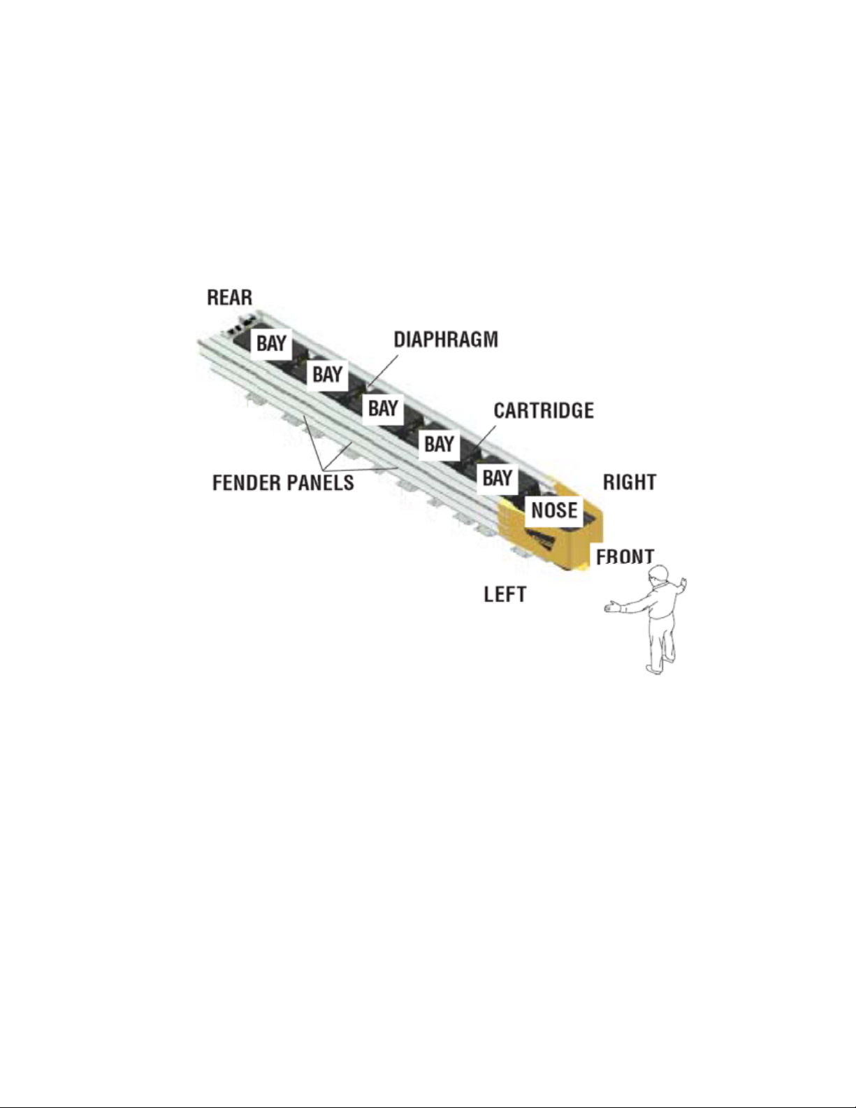
How to Determine Left/Right
To determine left from right when ordering parts, stand in front of the system facing the hazard.
Your left is the system’s left and your right is the system’s right.
Counting the Number of Bays
One Bay consists of one Cartridge, one Diaphragm, two Fender Panels, etc. The Nose section
is not considered a Bay, though there is a Cartridge in the Nose of each system. Note that this
means there will always be one more Cartridge in the system than the number of Bays in the
system. To determine number of Bays, count Fender Panels on one side (See Figure 1). Five
Bay system shown.
Figure 1
System Orientation

www.energyabsorption.com Revision F December 2012
www.highwayguardrail.com 9 All rights in copyright reserved
Measuring the Width
The QuadGuard
®
II system is available in seven nominal widths:
610 mm [24”]
760 mm [30”]
915 mm [36”]
1219 mm [48”]
1755 mm [69”]
2285 mm [90”]
3200 mm [126”]
The nominal width of a system with Tension Strut Backup is the width between Side Panels
behind the Backup (See Figure 2).
The nominal width of a system with Concrete Backup is the width of the Concrete Backup at
location shown in Figure 3.
The outside width of the system is approximately 150 mm [6”] to 230 mm [9”] wider than the
nominal width. The width of the system is not the same as the width of the Backup.
Figure 2
Width of system with Tension Strut Backup
(Minimum 3 Bays Required)
(Minimum 6 Bays Required)
Figure 3
Width of system with Concrete Backup

www.energyabsorption.com Revision F December 2012
www.highwayguardrail.com 10 All rights in copyright reserved
QuadGuard®II Deployment Criteria
Contact Energy Absorption Systems Customer Service Department if you would like input as to
your specific application. Proper model selection is essential to the performance of the
QuadGuard®II system. You will need to answer the following questions:
1) Specification of System Width
The QuadGuard®II system is available in seven nominal widths:
610 mm [24”]
760 mm [30”]
915 mm [36”]
1219 mm [48”]
1755 mm [69”]
2285 mm [90”]
3200 mm [126”] Minimum 6 Bays required
As a general rule, selection of the narrowest width that adequately shields the hazard is
recommended.
2) Specify System Length
System length is specified by the number of Bays the system includes. The number of Bays
required is a function of the design speed of the roadway.
3) Specify Foundation
Note that the system must be anchored. MP-3®polyester anchor bolts will be supplied for all
required anchorages in concrete. Refer to QuadGuard®II Assembly Manual or MP-3®kits for
detailed assembly instructions.
A. Is the system to be placed on existing concrete?
Existing concrete – Concrete must be at least 150 mm [6”] thick, reinforced 28 MPa
[4000psi] Portland cement concrete (P.C.C.), or 200 mm [8”] thick non-reinforced 28 MPa
[4000 psi] P.C. Concrete Roadway, measuring at least 3.66 m [12’-0”] wide by 15.24 m [50’-
0”] long. The concrete should be in good condition and be free of major cracks.
New concrete – If existing concrete does not meet these criteria, then a new concrete pad
must be placed to properly secure the system. See concrete pad details supplied with the
system.

www.energyabsorption.com Revision F December 2012
www.highwayguardrail.com 11 All rights in copyright reserved
B. Is there a cross-slope at the construction site?
Cross-slope exists – If there is a cross-slope of more than 8% (5 degrees), or if the
cross-slope varies (twists) more than 2% (1 degree) over the length of the system, a
concrete leveling pad may be required (See Figure 4).
No cross-slope – No additional action is required.
4) Specify Backup Structure
The two Backup designs available are the Tension Strut Backup and the Concrete Backup.
Both types are appropriate for use on grade or deck.
5) Special Site Conditions
Contact Energy Absorption Systems Customer Service Department if you would like input
with your application. You will need to answer the following questions:
1. Are curbs, islands or elevated objects (delineators or signs) present at the site?
What height and width are they? All curbs and elevated objects over 100 mm [4”] high
should be removed. If possible, curbs taller than 100 mm [4”] high should be removed
approximately 15 m [50’] in front of the QuadGuard
®
II systems and as far back as the
system’s Backup. Any curbs that must remain should be 100 mm [4”] maximum and be
mountable.
2. If the construction site is a gore area (place where two roads diverge), what is the angle
of divergence?
3. What is the general geometry of the site, including the roadway for at least 150 m
[500’] in front, so traffic patterns can be visualized?
4. Is there an existing barrier? Where there is an existing guardrail or median barrier at
the site, the Backup of the QuadGuard
®
II system should tie into it when possible.
5. Will there be traffic approaching from the rear of the system? Is the system in a
two-way traffic situation, with traffic going in opposite directions on either side of the
system? Or, is the system on the side of the road in a location where crossover traffic is
a concern? If so, a Transition from the back of the system to the hazard is necessary to
prevent vehicle interaction (See Page 20).
6. Are there any other unique features at the site that may affect positioning or
performance of the QuadGuard
®
II system?
Figure 4
Cross-Slope
www.energyabsorption.com Revision F December 2012
www.highwayguardrail.com 12 All rights in copyright reserved
6) Other Factors that May Affect Your Deployment:
1. The existence of drain inlets.
2. Junction boxes or other appurtenances located near the hazard.
3. Insufficient space for the length preferred.
4. The location and movement of expansion joints.
If these or any other special site conditions exist, please contact Energy Absorption Systems
Customer Service Department before proceeding with your design (See Page 3).
Impact conditions which differ from those described in the NCHRP 350 test matrix for non-
gating, redirecting crash cushions may result in different crash results than those
encountered in testing.
Furthermore, impacts in excess of TL-3 impact severity, or the existence (at the site of
assembly) of curbs or cross-slopes in excess of 8%, may yield performance which does not
meet NCHRP 350 evaluation criteria relative to structural adequacy, occupant risk and
vehicle trajectory factors.
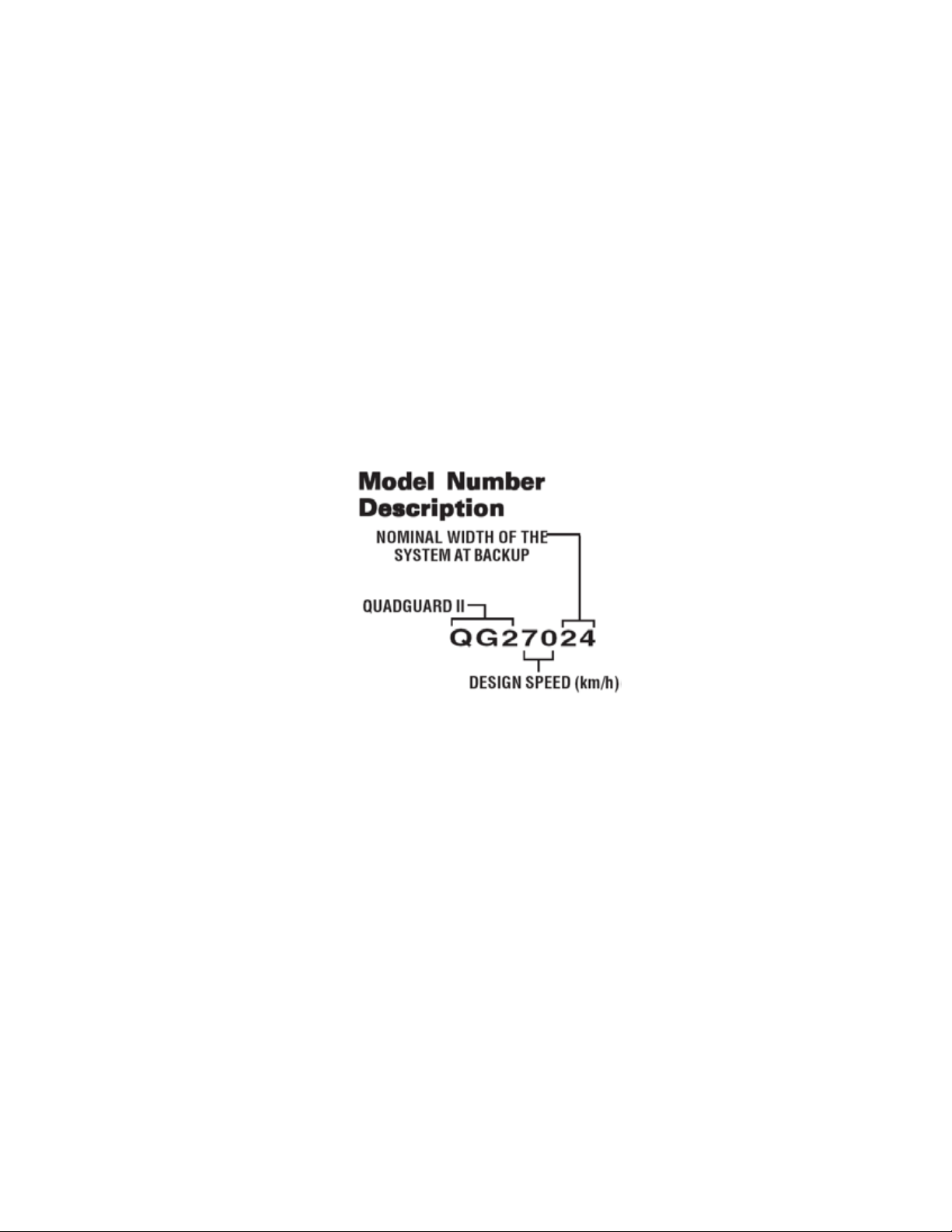
Figure 5
Model Number Key

www.energyabsorption.com Revision F December 2012
www.highwayguardrail.com 13 All rights in copyright reserved
These following charts represent the modified versions of the QG II length relative to impact
speed, which is based on the capacity of the system using a 2000 kg [4400 lb] pickup truck.
# of
Bays Model #
Vehicle
Speed
kph [mph]
Type I
Cartridge
Qty.
Type II
Cartridge
Qty.
1* QG 240_ _ 40 [25] 2 0
2 QG 270_ _ 70 [44] 2 1
3* QG 280_ _ 80 [50] 2 2
4* QG 290_ _ 90 [56] 3 2
5 QG 2100_ _ 100 [62] 3 3
6* QG 2105_ _ 105 [65] 4 3
7* QG 2110_ _ 110 [68] 4 4
8* QG 2115_ _ 115 [71] 4 5
9* QG 2120_ _ 120 [75] 4 6
# of
Bays Model #
Vehicle
Speed
kph [mph]
Type I
Cartridge
Qty.
Type II
Cartridge
Qty.
3* QG 270_ _ 70 [44] 2 2
4* QG 280_ _ 80 [50] 3 2
5* QG 2100_ _ 100 [62] 3 3
6* QG 2105_ _ 105 [65] 4 3
7* QG 2110_ _ 110 [68] 4 4
8* QG 2115_ _ 115 [71] 4 5
9* QG 2120_ _ 120 [75] 4 6
*System capacity estimated through calculation.
Table A – Speed Chart For Narrow Systems
Table B – Speed Chart For Wide Systems

www.energyabsorption.com Revision F December 2012
www.highwayguardrail.com 14 All rights in copyright reserved
Figure 6
Plan & Elevation
(5 Bay system with Tension Strut Backup shown)
3200 [126”] MODEL NO. QG2100126 (Min. 6 Bays required)
2285 MM [90”] MODEL NO. QG210090
QUADGUARD®II SYSTEM
FOR WIDE HAZARDS
QUADGUARD®II SYSTEM
FOR NARROW HAZARDS
1755 mm [69”] MODEL NO. QG210069
610 mm [24”] MODEL NO. QG210024
760 mm [30”] MODEL NO. QG210030
915 mm [36”] MODEL NO. QG210036
1219 mm [48”] MODEL NO. QG210048
5.83 m [19’-1”]
8.73 M [22’-1”]
www.energyabsorption.com Revision F December 2012
www.highwayguardrail.com 15 All rights in copyright reserved
Transitioning
Quad-Beam
™
End Shoe
Transition Panel
The Quad-Beam
™
End Shoe Panel transitions the QuadGuard
®
II system to vertical faced
concrete structures whether it is a concrete Backup or concrete barrier wall (See Page 20). An
Extended End Shoe is also available. In cases where the corners of the hazard are not
chamfered, it may be necessary to add wheel deflectors to the structure in order to prevent
wheel interaction.
Quad-Beam
™
to Guardrail Transition Panel (W-Beam and Thrie-Beam)
The Quad-Beam
™
to W-Beam and Quad-Beam
™
to Thrie-Beam Transition Panels transition the
QuadGuard
®
II system to new and existing runs of standard guardrail (See Page 16).
Quad-Beam
™
to Safety Barrier Transition Panel
There are several options available when transitioning the QuadGuard
®
II system to safety
shape barrier depending on the shape and position of the barrier.
When transitioning to barriers with a “New Jersey” style profile, the 4" offset Transition Panel is
most commonly used (See Page 16). For transitioning to barriers that are in line with the side of
the system, use transition assembly 616041B or 616044B. For transitioning a wide system to
barrier that runs parallel to the centerline of the system, transition assembly 616048B or
616049B is used. A 9" offset Transition Panel is also available for transitioning to barriers that
are in line with the side of the system.
When transitioning the Single Slope style barriers and parapets, 6” and 8” offset Transition
Panels are available. For transitioning a wide system to barrier that runs parallel to the
centerline of the system, a 6” offset panel is available.
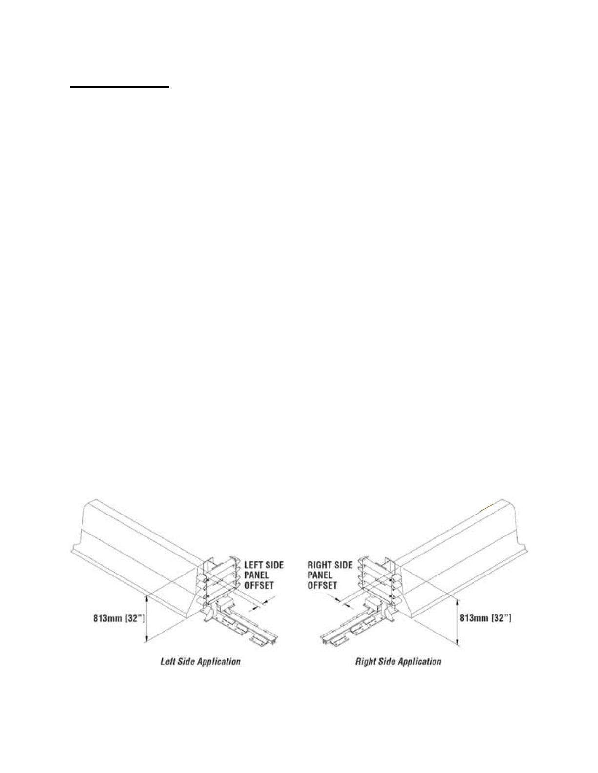
How do you determine the Transition Panel offset?
Transition Panel offset is determined by measuring the distance between the face of the barrier
and the top edge of the Backup Diaphragm at 32" above ground level (See Figure 7).
Remember, when assembling the QuadGuard
®
II System that the correct Transition Panel offset
must be achieved in order for the offset bracket to nest between the barrier and Transition Panel
ensuring proper performance of the transition.
Figure 7
Transition Panel Offset

www.energyabsorption.com Revision F December 2012
www.highwayguardrail.com 16 All rights in copyright reserved
Transition Panel Types
If a system is placed in a location where traffic will be approaching from the rear, a Transition
Panel is necessary. Figure 8, 9, 10 and 11 show standard panel types. There are variations for
each panel type. The specific panel applied will depend on system and site conditions.
Therefore, it is important to send site specific data to the customer service department for a
recommendation for exact panel requirements of your application.
Figure 8
Quad-Beam
™
to Safety Barrier (NJ
shape) Transition Panel
Figure 9
Quad-Beam
™
to Thrie-Beam
Transition Panel
Figure 10
Quad-Beam
™
to W-Beam Transition Panel Figure 11
Quad-Beam
™
End Shoe Transition Panel
www.energyabsorption.com Revision F December 2012
www.highwayguardrail.com 17 All rights in copyright reserved
QuadGuard
®
II cz Deployment Criteria
This portable compact crash cushion is for construction zones. The QuadGuard
®
II cz is
available in the same narrow sizes as permanent systems.
The QuadGuard
®
II cz must be properly anchored (See Pages 15 and 16 for the recommended
anchorage of various foundations).
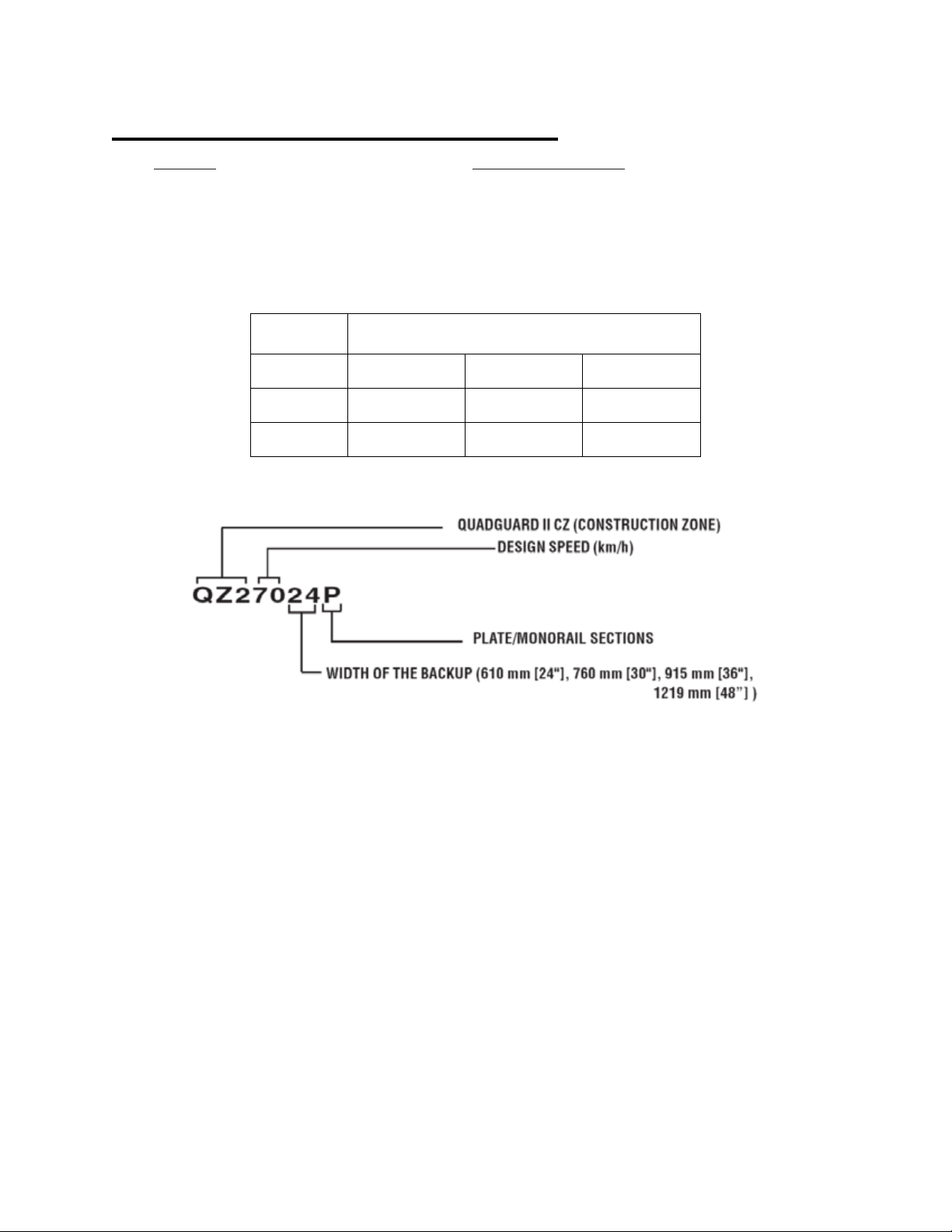
Table C
QuadGuard
®
II cz Plate Model Numbers
Number of
Bays NOMINAL WIDTH
610 MM [24”] 760 MM [30”] 915 MM [36”]
2 QZ27024P QZ27030P QZ27036P
5 QZ210024P QZ210030P QZ210036P
Model Number Description
Figure 12
Model Number Key

www.energyabsorption.com Revision F December 2012
www.highwayguardrail.com 18 All rights in copyright reserved
QuadGuard®II Foundation/Anchoring
Concrete Installations
For concrete installations, the QuadGuard®II system should be installed only on an existing or
freshly placed and cured concrete base (28 MPa [4000 psi] minimum). Orientation of the
concrete base and the attenuator must comply with the project plans or as otherwise
determined by the resident project engineer or appropriate highway authority.
Recommended dimension and reinforcement specifications for new concrete pads can be found
on the standard drawings.
Asphalt Installations
For asphalt installations in construction zones, QuadGuard®II system may only be assembled
with a Tension-Strut Backup. Assemblies on asphalt must provide a minimum of 76 mm [3”]
layer of asphalt over a minimum of 76 mm [3”] layer of Portland Cement concrete, 152 mm [6”]
layer of asphalt over 152 mm [6”] layer of subbase, or 203 mm [8”] layer of asphalt with no
subbase. 460 mm [18”] threaded rods, installed with the two-part MP-3®grout, must be used for
these foundations.
Important: Systems mounted on asphalt must be replaced and mounted on
fresh, undisturbed asphalt if more than 10% of anchors are found to be loose,
broken, or show signs of pull out. If 10% or fewer anchors are damaged, replace
the damaged anchors in the existing asphalt. Anchor bolts used on systems
mounted on asphalt must be inspected every 6 months. See Post Impact
Instructions and Maintenance and Repair instructions in the QuadGuard II
Assembly Manual for details.
The QuadGuard®II system may be installed on any of the following foundations using the
specified anchorage:
Foundation A: Concrete Pad or Roadway
Foundation: 150 mm [6”] minimum depth Portland Cement Concrete (P.C.C.)
Anchorage: MP-3® with 180 mm [7”] studs 140 mm [5 1/2”] embedment
Foundation B: Asphalt over P.C.C.
Foundation: 76 mm [3”] minimum asphalt concrete (A.C.) over 76 mm [3”] minimum P.C.C.
Anchorage: Length of anchor required is 180 mm [18”] 420 mm [16 1/2”] embedment
Foundation C: Asphalt over Subbase
Foundation: 150 mm [6"] minimum A.C. over 150 mm [6”] minimum Compacted Subbase
(C.S.)
Anchorage: MP-3 with 460 mm [18"] studs 420 mm [16 1/2”] embedment
Foundation D: Asphalt Only
Foundation: 200 mm [8”] minimum A.C.
Anchorage: MP-3with 460 mm [18”] studs - 420 mm [16 1/2”] embedment
Foundation Specifications
for Foundations A, B, C and D mentioned above:

www.energyabsorption.com Revision F December 2012
www.highwayguardrail.com 19 All rights in copyright reserved
A. C. (Asphalt Concrete)
AR-4000 A. C. (per ASTM D3381 '83) 3/4” Maximum, Medium (Type A or B) aggregate
Sieve Size Operating Range (%) Passing
1" 100
3/4" 95-100
3/8" 65-80
No. 4 49-54
No. 8 3 6-40
No. 30 1 8-21
No. 200 3-8
Caution: Walk-up inspections are recommended at least once every six
months for installations on asphalt.
P.C.C. (Portland Cement Concrete)
Stone aggregate concrete mix
4000 psi minimum compressive strength
(Sampling per ASTM C31-84 or ASTM C42-84a, testing per ASTM C39-84)
C.S. (Compacted Subbase)
150 mm [6”] minimum depth 95% compaction
Class 2 aggregate
Sieve Size Moving Average % Passing
3" 100
2 1/2" 90-100
No. 4 40-90
No. 200 0-25
This manual suits for next models
1
Table of contents
Other Trinity Highway Industrial Equipment manuals


