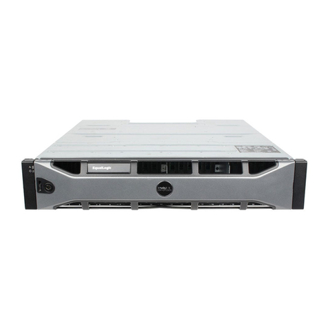
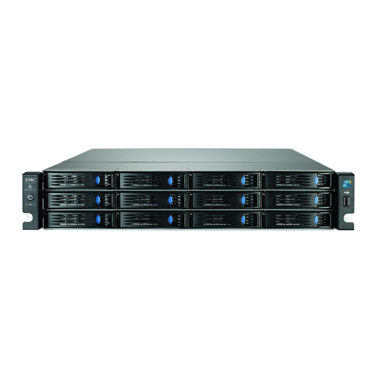
Dell EMC NX4 Series User manual

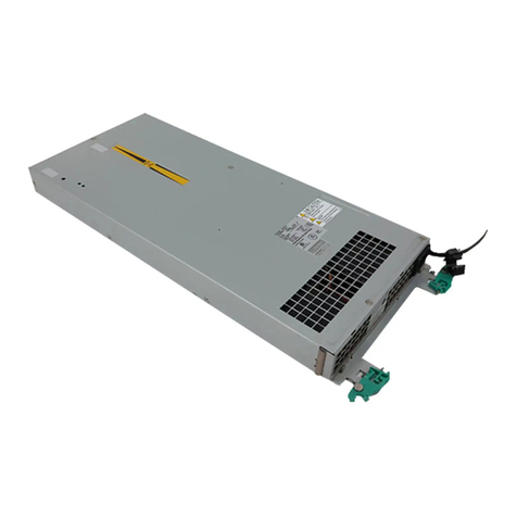
This document describes how to replace a standby power supply (SPS) in the storage system in
an NX4 system.
Note: The storage system in an NX4 system is an AX4-5F8.
Summary of tasks for replacing an SPS................................................................................................................2
Handling field replaceable units (FRUs)..............................................................................................................3
Disabling CallHome or ConnectHome and Email notifications......................................................................5
Shutting down power and removing the cables.................................................................................................7
Unlocking and removing the SPS front bezel.....................................................................................................8
Removing the front plate........................................................................................................................................9
Removing a standby power supply....................................................................................................................10
Installing a standby power supply.....................................................................................................................11
Reconnecting Cables and Powering up the SPS................................................................................................12
Installing the front plate.......................................................................................................................................13
Installing and locking the SPS front bezel.........................................................................................................14
Verifying the operation of a new or replacement part.....................................................................................15
Restoring trespassed virtual disks or LUNs using the CLI ............................................................................17
Checking system status........................................................................................................................................18
Enabling CallHome or ConnectHome and Email notifications......................................................................19
Returning the failed part......................................................................................................................................23
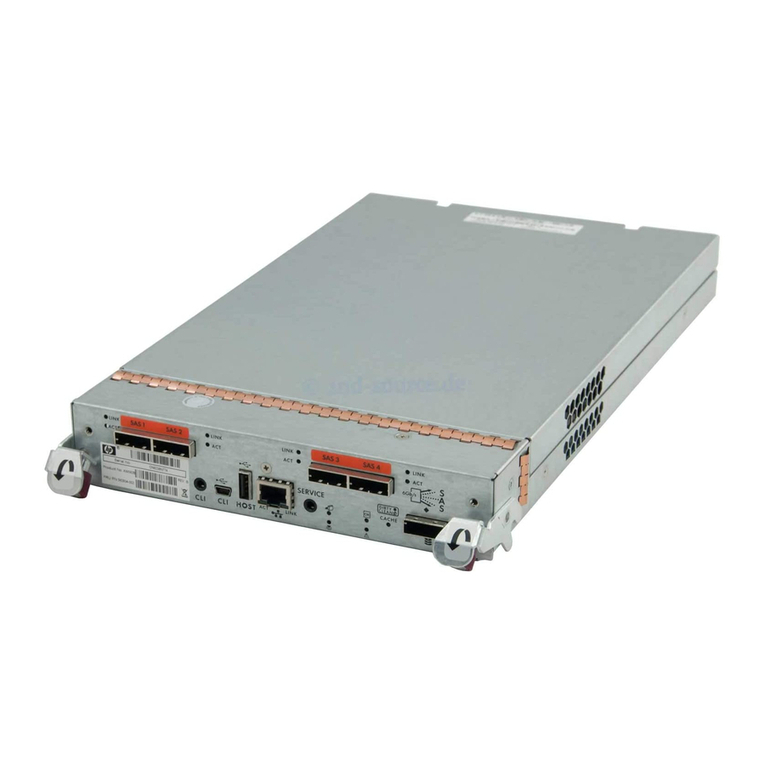
EMC®AX4-5F8 Architecture for NX4 Series
Replacing a Standby Power Supply

Summary of tasks for replacing an SPS
To replace an SPS you must complete the tasks below in the order in which they appear.
This document provides instructions for completing each task.
1. Disable CallHome or ConnectHome.
2. Shut down the failed SPS and remove all cables.
3. Unlock and remove the bezel.
4. Remove the front plate.
5. Remove the failed SPS.
6. Install the replacement SPS.
7. Reinstall the front plate.
8. Reconnect cables and power up the replacement SPS.
9. Reinstall the front plate.
10. Reinstall and lock the bezel.
11. Verify the operation of the replacement SPS.
12. Restore any trespassed virtual disks or LUNs.
13. Check system status.
14. Enable CallHome or ConnectHome.
2Replacing a Standby Power Supply
Summary of tasks for replacing an SPS

Handling field replaceable units (FRUs)
This section describes the precautions that you must take and the general procedures that
you must follow when removing, installing, and storing any field replaceable unit (FRU).
Power issues and FRUs
Your storage system is designed to be powered on continuously. Most components are hot
swappable; that is, you can replace or install these components while the storage system is
running. Front bezels should always be attached and each compartment should contain a
FRU or filler panel to ensure EMI compliance and proper air flow over the FRUs.
You should not remove a faulty FRU until you have a replacement available.
When you replace or install FRUs, you can inadvertently damage the sensitive electronic
circuits in the equipment by simply touching them. Electrostatic charge (ESD) that has
accumulated on your body discharges through the circuits. If the air in the work area is very
dry, running a humidifier in the work area will help decrease the risk of ESD damage. Follow
the procedures below to prevent damage to the equipment.
Read and understand the following instructions:
◆Provide enough room to work on the equipment. Clear the work site of any unnecessary
materials or materials that naturally build up electrostatic charge, such as foam packaging,
foam cups, cellophane wrappers, and similar items.
◆Do not remove replacement or upgrade FRUs from their antistatic packaging until you
are ready to install them.
◆Before you service a storage system, gather together the ESD kit and all other materials
you will need. Once servicing begins, avoid moving away from the work site; otherwise,
you may build up an electrostatic charge.
◆An ESD wristband is supplied with your storage system. To use it, attach the clip of the
ESD wristband (strap) to any bare (unpainted) metal on the storage system; then put the
wristband around your wrist with the metal button against your skin.
◆Use the ESD kit when handling any FRU. If an emergency arises and the ESD kit is not
available, follow the procedures in the Emergency procedures (without an ESD kit) on
page 3.
Emergency procedures (without an ESD kit)
In an emergency when an ESD kit is not available, use the procedures below to reduce the
possibility of an electrostatic discharge by ensuring that your body and the subassembly
are at the same electrostatic potential. These procedures are not a substitute for the use of
an ESD kit. Follow them only in the event of an emergency.
Handling field replaceable units (FRUs) 3
Handling field replaceable units (FRUs)
◆Before touching any FRU, touch a bare (unpainted) metal surface of the cabinet or storage
system.
◆Before removing any FRU from its antistatic bag, place one hand firmly on a bare metal
surface of the storage system, and at the same time, pick up the FRU while it is still sealed
in the antistatic bac. Once you have done this do not move around the room or touch
other furnishings, personnel, or surfaces until you have installed the FRU.
◆When you remove a FRU from the antistatic bag, avoid touching any electronic
components and circuits on it.
◆If you must move around the room or touch other surfaces before installing a FRU, first
place the FRU back in the antistatic bag. When you are ready again to install the FRU,
repeat these procedures.
4Replacing a Standby Power Supply
Handling field replaceable units (FRUs)
Disabling CallHome or ConnectHome and Email notifications
Open a HyperTerminal session with the Celerra system and then use procedure in the section
that follows for your EMCNAS version to disable CallHome or ConnectHome and Email
notification.
Opening a HyperTerminal session with the system
1. At the rear of the cabinet, connect the null modem cable (P/N 038-003-458) from the serial
port on the service laptop to the primary Control Station (Figure 1 on page 5).
Serial port
Figure 1. Control station serial connection
2. Open the HyperTerminal session using the following settings:
19200Bits per second:
8Data bits:
NoneParity:
1Stop bits:
NoneFlow control:
Auto DetectEmulation:
ANSITelnet terminal ID:
Note: If you cannot connect to the HyperTerminal session, reboot the Control Station, log in, and
repeat this step.
3. Login as nasadmin:
login:nasadmin
4. Become the root user:
$ su root
Password:
Disabling CallHome or ConnectHome and Email notifications 5
Disabling CallHome or ConnectHome and Email notifications

For EMCNAS 5.6 or later
Use a HyperTerminal session to disable ConnectHome:
1. From the root directory, disable CallHome:
/nas/sbin/nas_connecthome stop
2. Disable the Email notification service:
/nas/bin/nas_emailuser -modify -enabled
Sample output:
OK
3. Verify that the Email notification service has stopped (is not enabled):
/nas/bin/nas_emailuser-info
Sample output:
Service Enabled = No
Carbon Copy Address(es) =
Email Server = emcmail.lss.emc.com
Subject Prefix = Celerra Notification -NDU through NST Sender Address =
ConnectHome and Email notifications are now disabled. You are now ready to replace the
part. After completing the part replacement procedure, be sure to enable ConnectHome and
Email notifications.
6Replacing a Standby Power Supply
Disabling CallHome or ConnectHome and Email notifications

Shutting down power and removing the cables
1. Shut down power on the SPS that you are replacing by pressing the left side of the SPS
power switch (Figure 2 on page 7).
Figure 2. Off position for the SPS power switch (SPS A shown)
2. Disconnect the SPS cables:
Note: Label the cables for reinstallation later.
a. Unplug the SPS power cord from the site power source and then from the SPS.
b. From the SPS, unplug the sense cable and the power cord connecting the SPS to the
SP directly above it.
Shutting down power and removing the cables 7
Shutting down power and removing the cables

Unlocking and removing the SPS front bezel
1. Unlock the front bezel by turning the key at the front of the enclosure counterclockwise.
2. Press the buttons on the front of the bezel and pull the bezel toward you to release it.
3. Save the bezel for reinstallation later.
Figure 3. Unlocking and removing the front bezel
8Replacing a Standby Power Supply
Unlocking and removing the SPS front bezel

Removing the front plate
The front plate covers the front of the SPS tray. You must remove it to replace either SPS.
1. Remove the four or six screws on the front plate and remove the front plate (Figure 4 on
page 9).
Figure 4. Removing the front plate
2. Save the front plate and screws for reinstallation later.
Removing the front plate 9
Removing the front plate

Installing a standby power supply
1. Remove the SPS from its packaging.
2. From the front, slide the SPS onto the tray and into position (Figure 6 on page 11).
3. From the rear, secure the SPS with four screws that you saved either from removing the
back plate (if you are adding a second SPS) or from removing from a failed SPS (if you
are replacing an SPS).
Figure 6. Installing a standby power supply
Installing a standby power supply 11
Installing a standby power supply

Reconnecting Cables and Powering up the SPS
1. Reconnect the sense cable from the SPS serial port (marked with a battery symbol) on
management module to the SPS (detailed in reconnecting the sense cable and power
cords).
2. Reconnect the power cables to the replacement SPS as shown in and described in the
steps that follow the figure.
a. Connect the power cord to the power distribution unit (PDU) in the cabinet or the
site power circuit and to the SPS.
3. Power up the SPS by pressing the right side of the SPS power switch (Figure 7 on page
12).
Figure 7. On position for the SPS switch (SPS A shown)
12 Replacing a Standby Power Supply
Reconnecting Cables and Powering up the SPS

Installing the front plate
1. Reposition the front plate and secure it with the screws that you saved when you removed
the plate (Figure 8 on page 13).
2. If you are adding a second SPS, secure that SPS to the front plate with two additional
screws that came with the SPS upgrade kit (Figure 8 on page 13).
Figure 8. Installing the front plate
Installing the front plate 13
Installing the front plate

Installing and locking the SPS front bezel
1. While holding the front SPS bezel by its edges, attach it to the latch brackets on the front
of the enclosure (Figure 9 on page 14).
2. Push the bezel in until you feel it latch into place, and pull back on the bezel slightly to
ensure it is secured.
3. Lock the bezel by inserting and then turning the key clockwise (Figure 9 on page 14).
Figure 9. Installing and locking the SPS bezel
14 Replacing a Standby Power Supply
Installing and locking the SPS front bezel

Verifying the operation of a new or replacement part
Use Navisphere Express®or Navisphere®Manager to verify the operation of a new or
replacement part.
If the storage system is running Navisphere Express, use Navisphere Express to verify the
operation of a new or replacement part.
If the storage system is running Navisphere Manager, use Navisphere Manager to verify
the operation of a new or replacement part.
Note: All AX4-5 series storage systems ship with Navisphere Express installed. To use Navisphere
Manager, you need to upgrade your storage system to Navisphere Manager.
Verify the operation of a new or replacement part using Navisphere
Express
1. In a browser on a network-connected host, start Navisphere®Express for the storage
system by entering the IP address of an SP in the storage system.
2. In the Navisphere Express navigation pane, under View, click Components.
3. Scan the list of components to verify that all components are recognized and working
properly.
If fault lights on storage system are still lit, go to the Celerra Tools page on the
http://Powerlink.EMC.com website for more information.
Verifying the operation of a new or replacement part using Navisphere
Manager
1. Start Navisphere®Manager for the storage system by entering the IP address in a browser
window.
2. In the Navisphere Manager Storage tree, locate the icon for the storage system in which
you installed or replaced the part, expand the storage-system icon, and select the Physical
icon.
3. Expand the enclosure in which you installed or replaced the part, and navigate to the
part.
4. Verify that the part is in the enclosure and that it is not faulted.
Verifying the operation of a new or replacement part 15
Verifying the operation of a new or replacement part

Restoring trespassed virtual disks or LUNs using the CLI
When a backend FRU/CRU component fails, the virtual disks or LUNs assigned to that
storage processor trespass to the other storage processor. This keeps the data available to
the clients. After replacing the failed backend FRU/CRU component you need to restore the
virtual disks or LUNs to their original storage processor.
1. Using the CLI, log in to the primary Control Station as nasadmin and change to the root
user:
su root
2. Determine the storage-system serial number (storage-system ID):
nas_storage -list
3. Restore the virtual disks or LUNs to the correct SP:
nas_storage –failback storage-system-id
For example:
# nas_storage -failback APM00070300923
id = 1
serial_number = APM00070300923
name = APM00070300923
acl = 0
done
This restores the virtual disks or LUNs to the correct SP. After the restore, both SPs have
their status listed as OK.
Restoring trespassed virtual disks or LUNs using the CLI 17
Restoring trespassed virtual disks or LUNs using the CLI

Checking system status
Before you begin
You should still be in your HyperTerminal session.
Procedure
To view the system state:
1. Enter the following command to verify the system state:
# /nas/bin/nas_checkup
Example:
# /nas/bin/nas_checkup
]# /nas/bin/nas_checkup
Check Version: <NAS_version>
Check Command: /nas/bin/nas_checkup
Check Log : /nas/log/checkup-run.100128-181007.log
-------------------------------------Checks-------------------------------------
Control Station: Checking if file system usage is under
limit.............. Pass
Control Station: Checking if NAS Storage API is installed
correctly........ Pass
Control Station: Checking if NBS clients are
started....................... Pass
Control Station: Checking if NBS configuration
exists...................... Pass
Control Station: Checking if NBS devices are
accessible.................... Pass
Control Station: Checking if NBS service is
started........................ Pass
Storage System : Checking for unsupported storage
profile.................. Pass
Storage System : Checking if Fibre Channel zone checker is set
up.......... N/A
Storage System : Checking if Fibre Channel zoning is
OK.................... N/A
Storage System : Checking if proxy arp is
setup............................ Pass
Storage System : Checking SPA SPB
communication............................ Pass
--------------------------------------------------------------------------------
If the output of the nas_checkup command indicates any problems, correct the problems
and re-do the command before continuing.
18 Replacing a Standby Power Supply
Checking system status

Enabling CallHome or ConnectHome and Email notifications
Use the procedure in the section that follows for your EMCNAS version to enable CallHome
or ConnectHome and Email notification.
For EMCNAS 5.6 or later
Use a HyperTerminal session to enable ConnectHome and Email notification:
1. From the root directory, clear any existing Callhome files and enable ConnectHome:
/nas/sbin/nas_connecthome -service start -clear
2. From the ConnectHome configuration, determine the connections that are enabled:
/nas/sbin/nas_connecthome -i
Sample output:
Enabling CallHome or ConnectHome and Email notifications 19
Enabling CallHome or ConnectHome and Email notifications

ConnectHome Configuration:
Encryption Enabled = yes
Dial In:
Enabled = yes
Modem phone number =
Site ID =
Serial number = HK192201084
Email:
Priority = 1
Subject = CallHome Alert
Primary:
Email Server = sun1.hosts.pvt.dns
Secondary:
Email Server =
FTP:
Priority = Disabled
Primary:
FTP Server =
FTP Port = 21
FTP User Name = onalert
FTP Password = **********
FTP Remote Folder = incoming
FTP Transfer Mode = active
Secondary:
FTP Server =
FTP Port = 21
FTP User Name = onalert
FTP Password = **********
FTP Remote Folder = incoming
FTP Transfer Mode = active
Modem:
Priority = Disabled
Primary:
Phone Number = 918005270941
BT Tymnet = no
Secondary:
Phone Number = 918006262452
BT Tymnet = no
3. Verify that ConnectHome works with the /nas/sbin/nas_connecthome -test connec
tion_name command for each enabled connection.
For example:
/nas/sbin/nas_connecthome -t -email_1
Sample output:
-----------------------------------------------------
ConnectEMC 2.0.27-bl18 Wed Aug 22 10:24:32 EDT 2007
RSC API Version: 2.0.27-bl18
Copyright (C) EMC Corporation 2003-2008, all rights
reserved.
-----------------------------------------------------
Reading configuration file: ConnectEMC.ini.
Run Service begin...
Test succeeded for primary email.
20 Replacing a Standby Power Supply
Enabling CallHome or ConnectHome and Email notifications
This manual suits for next models
1
Table of contents
Other Dell Disk Array System manuals