Dell S2422HZ User manual
Other Dell Monitor manuals

Dell
Dell 1905FP User instructions
Dell
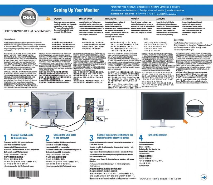
Dell 3007WFP-HC - UltraSharp - 30" LCD Monitor User manual

Dell
Dell P992 User manual
Dell
Dell C5519Q User manual

Dell
Dell P2419HCB Instructions for use

Dell
Dell S199WFP - 19" LCD Monitor User manual
Dell
Dell BN68-00344E-00 User manual
Dell
Dell S3423DWC User manual
Dell
Dell UltraSharp UP3221Q User manual
Dell
Dell P4317Q User manual
Dell
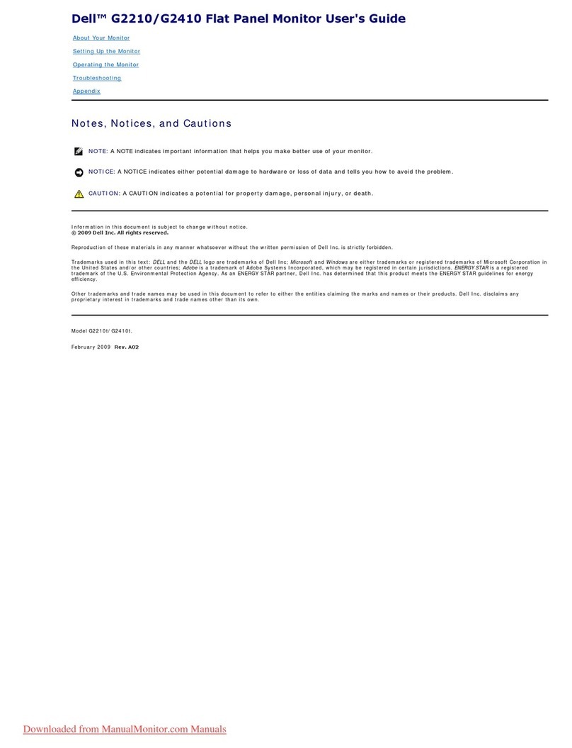
Dell G2210 User manual

Dell
Dell C5518QT User manual
Dell
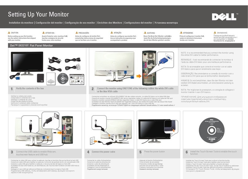
Dell SX2210T User manual
Dell
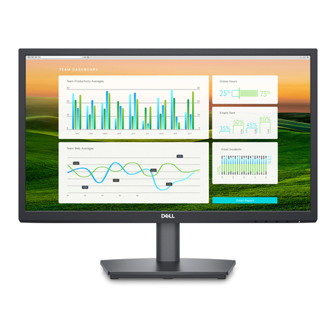
Dell E2222HS Instructions for use

Dell
Dell UltraSharp 1800FP User manual
Dell
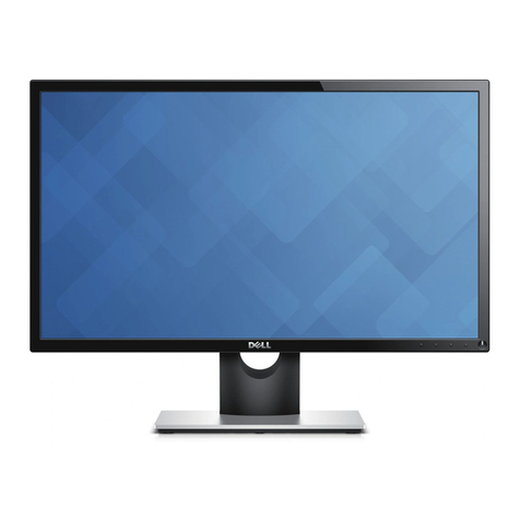
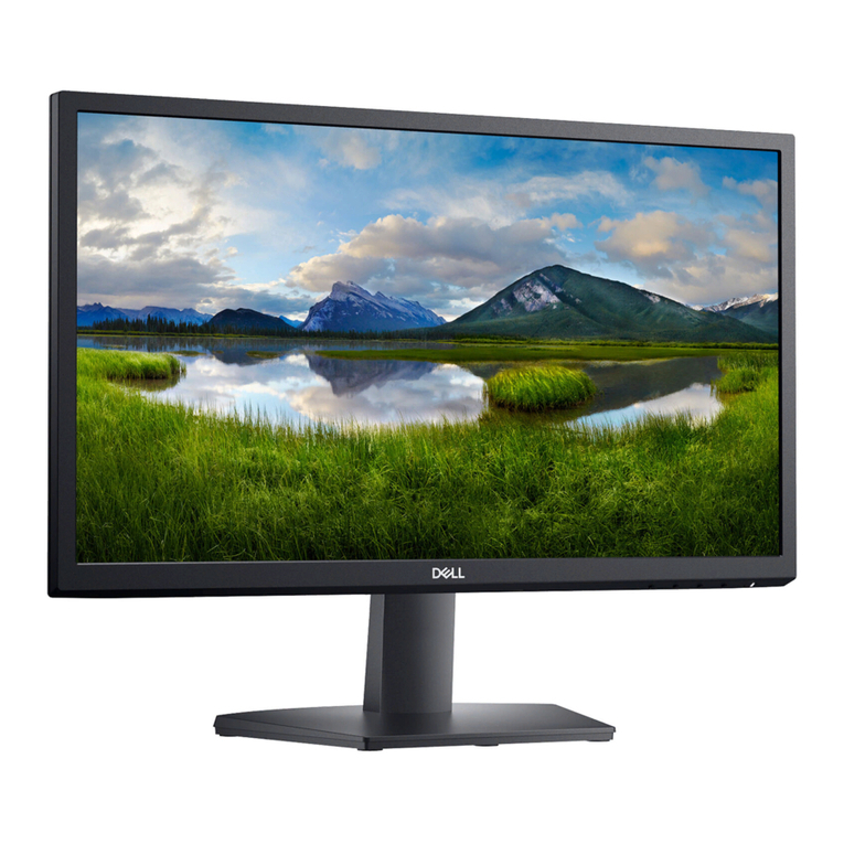
Dell SE2416H User manual
Dell
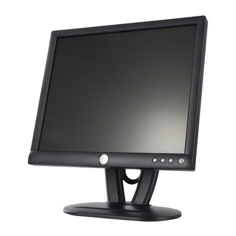
Dell E193FPc User manual
Dell
Dell S1909WN User manual
Dell
Dell SE2222H Installation instructions

Dell
Dell D3218HN User manual


