Installation Guide 1-1
CAUTION: Safety Instructions
Use the following safety guidelines to help ensure your own personal safety and to help
protect your system and working environment from potential damage. For complete safety
information, see the System Information Guide.
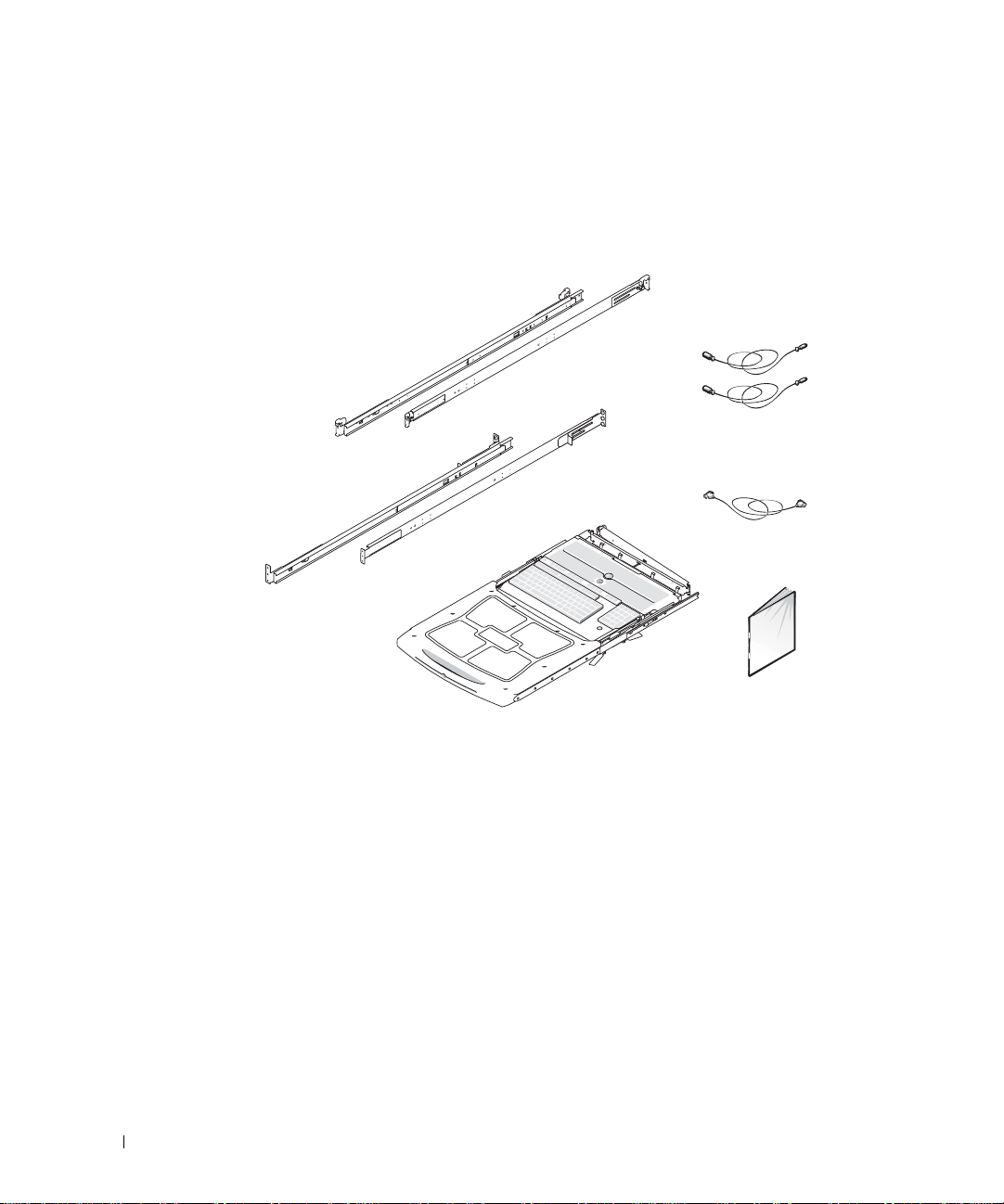
Rack Mounting of Systems
Observe the following precautions for rack stability and safety.
Systems are considered to be components in a rack. Thus, "component" refers to any
system as well as to various peripherals or supporting hardware.
CAUTION: Installing systems in a rack without the front and side stabilizers
installed could cause the rack to tip over, potentially resulting in bodily injury
under certain circumstances. Therefore, always install the stabilizers before
installing components in the rack.
After installing system/components in a rack, never pull more than one
component out of the rack on its slide assemblies at one time. The weight of
more than one extended component could cause the rack to tip over and may
result in serious injury.
NOTE: Your system is safety-certified as a free-standing unit and as a component for
use in a Dell™ rack cabinet using the customer rack kit. The installation of your
system and rack kit in any other rack cabinet has not been approved by any safety
agencies. It is your responsibility to ensure that the final combination of system and
rack complies with all applicable safety standards and local electric code
requirements. Dell disclaims all liability and warranties in connection with such
combinations.
• System rack kits are intended to be installed in a rack by trained service technicians. If
you install the kit in any other rack, be sure that the rack meets the specifications of a
Dell rack.
CAUTION: Do not move racks by yourself. Due to the height and weight of the
rack, a minimum of two people should accomplish this task.
• Before working on the rack, make sure that the stabilizers are secured to the rack,
extended to the floor, and that the full weight of the rack rests on the floor. Install
front and side stabilizers on a single rack or front stabilizers for joined multiple racks
before working on the rack.
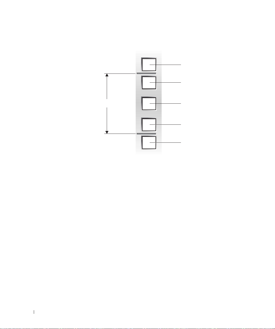
• Always load the rack from the bottom up, and load the heaviest item in the rack first.
• Make sure that the rack is level and stable before extending a component from the
rack.
8x738bk0.book Page 1 Monday, April 28, 2003 10:21 AM