manuals.online logo
Brands
  1. Home
  2. •
  3. Brands
  4. •
  5. Dell
  6. •
  7. Server
  8. •
  9. Dell PowerEdge 2450 Technical manual

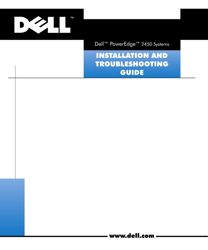
Dell PowerEdge 2450 Technical manual

  !





Throughout this guide, blocks of text may be accompanied by an icon and printed in
bold type or in italic type. These blocks are notes, notices, cautions, and warnings,
and they are used as follows:
NOTE: A NOTE indicates important information that helps you make better use of your
computer system.


  !"
"#
$%&$%&!"
"#
____________________
Information in this document is subject to change without notice.
© 2000 Dell Computer Corporation. All rights reserved.
Reproduction in any manner whatsoever without the written permission of Dell Computer
Corporation is strictly forbidden.
Trademarks used in this text: Dell, the DELL E COM logo, and PowerEdge are trademarks of
Dell Computer Corporation; Intel and Pentium are registered trademarks of Intel Corporation.
Other trademarks and trade names may be used in this document to refer to either the entities
claiming the marks and names or their products. Dell Computer Corporation disclaims any propri-
etary interest in trademarks and trade names other than its own.
August 2000 P/N 06NWC Rev. A01
support.dell.com Dell PowerEdge 2450 Systems Information Update 1-1


This document updates information on the following topics for your
Dell PowerEdge 2450 system:
Installing and removing expansion cards
Small computer system interface (SCSI) hard-disk drive support
Installing an upgrade microprocessor in PowerEdge 2450 systems

 
To install an expansion card, perform the following steps.
$%&'"
("

1. Turn off the system, including any attached peripherals, and disconnect the sys-
tem from the electrical outlet.
2. Prepare the expansion card for installation, and open the system doors.
)*+,-

See the documentation that came with the expansion card for information on
configuring the card, making internal connections, or otherwise customizing the
card for your system.
3. Check any cables connected to expansion cards through the back-panel open-
ings. Disconnect any cables that will not reach to where the cage must be placed
upon removal from the chassis.
./,

1-2 Dell PowerEdge 2450 Systems Information Update

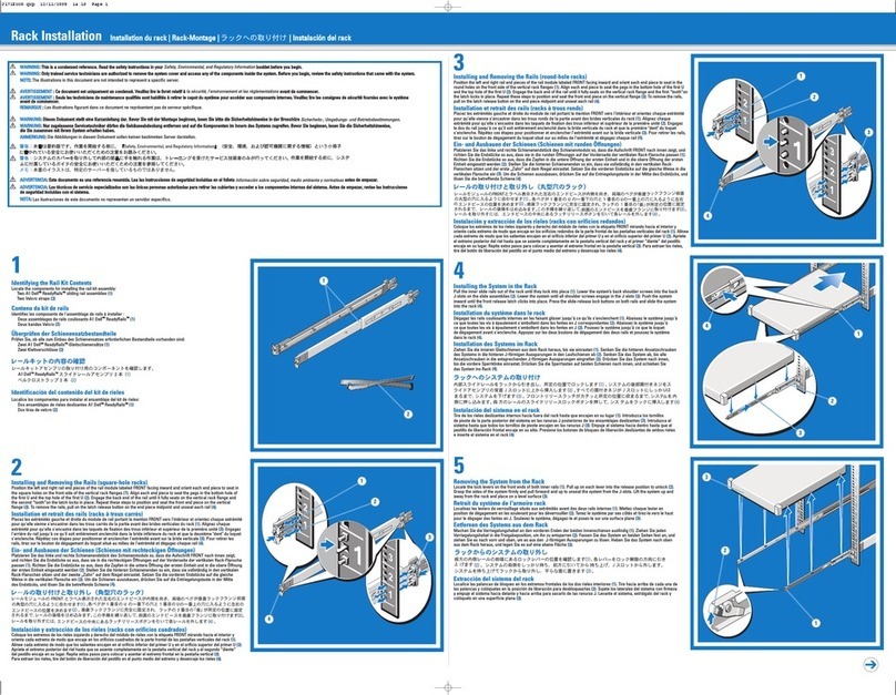
4. Locate the expansion-card cage securing lever (see Figure 1-1). Rotate the lever
upward until it stops in an upright position.
5. Lift the expansion-card cage up and away from the chassis.
6. Open the expansion-card latch (see Figure 1-2) and remove the filler bracket from
the expansion slot.

securing lever
expansion-card cage
expansion-card cage
expansion card
card-edge connector
expansion-card connector
riser board
expansion-card latch
card guide
support.dell.com Dell PowerEdge 2450 Systems Information Update 1-3
7. Install the new expansion card.
Position the expansion-card cage so that the riser board lies horizontally on your
work surface.
Insert the card-edge connector firmly into the expansion-card connector on the
riser board, until the card is fully seated.
8. When the card is seated in the connector and the card-mounting bracket is
aligned with the brackets on either side of it, close the expansion-card latch.
9. If the expansion card is a full-length card, secure the inner end of the card by
closing the latch on the card guide over the top edge of the card.
10. With the securing lever in the upright position, lower the expansion-card cage
into place until it is aligned.
11. Rotate the securing lever downward until it is flush with the top of the chassis.
Make sure the riser board is fully seated in the RISER connector on the system
board.
12. Reconnect any cables you removed in step 3.
See the documentation that came with the card for information about its cable
connections.
13. Close the system doors, and then reconnect the system and peripherals to their
AC power sources and turn them on.
To remove an expansion card, perform the following steps:
1. To release the expansion card from the card cage, rotate the expansion-card latch
away from the expansion-card bracket.
2. If the expansion card is a full-length card, release the card's inner end by opening
the tab on the card guide (see Figure 1-2).
3. Grasp the expansion card by its top corners, and carefully remove it from the
expansion-card connector.
4. If you are removing the card permanently, install a metal filler bracket over the
empty card-slot opening.
NOTE: Installing a filler bracket over an empty expansion slot is necessary to
maintain Federal Communications Commission (FCC) certification of the system.
The brackets also keep dust and dirt out of the system and aid in proper cooling
and airflow inside the system.
5. Replace the expansion-card cage in the chassis as instructed in steps 10 through
12 of the previous procedure.
6. Close the system doors, and then reconnect the system and peripherals to their
AC power sources and turn them on.
1-4 Dell PowerEdge 2450 Systems Information Update

Your system’s integrated SCSI host adapter supports the Ultra3 (also known as
Ultra160) SCSI standard as defined by the SCSI Trade Association. The Ultra3 SCSI
standard supports a combination of new SCSI performance and manageability
enhancements to increase data throughput up to 160 megabytes per second
(MB/sec). For specific information about the Ultra3 SCSI standard, see the SCSI Trade
Association Web site at http://www.scsita.org.
Your system employs an implementation of Ultra3 (Ultra160) known as Ultra160/m.
The Ultra160/m and Ultra3 (Ultra160) drives supplied by Dell are identical and are
interchangeable.
The subsections describing SCSI and redundant array of independent disks (RAID)
settings in “Using the System Setup Program,” of your Dell PowerEdge 2450
Systems User’s Guide have been combined to read as follows:
SCSI/RAID Controller
Selections are RAID Enabled, SCSI Enabled, and Off. When you set the
SCSI/RAID Controller to RAID Enabled, Channel A displays RAID and
Channel B displays SCSI. When you set it to SCSI Enabled, Channel A and
Channel B display SCSI. When you set it to Off, Channel A and Channel B
display Off.
When installing the SCSI backplane daughter card as addressed in “Installing Hard-
Disk Drives,” of the Dell PowerEdge 2450 Systems Installation and Troubleshooting
Guide, make sure to slide in the daughter card until it clicks and then lock the card into
place by closing the retention lever on the card’s front edge.

 !"#$
This section provides instructions for:
Removing the single edge contact (SEC) cartridge and heat sink
Installing the new SEC cartridge and heat sink

Before you perform any of the procedures in this section, take a few moments to read
the following warning for your personal safety and to prevent damage to the system
from electrostatic discharge (ESD).
$%&(
0
Before you start to work on the system, perform the following steps in the
sequence listed:
1. Turn off your system and any devices.
support.dell.com Dell PowerEdge 2450 Systems Information Update 1-5
2. Ground yourself by touching an unpainted metal surface on the chassis, such as
the metal around the card-slot openings at the back of the system, before touch-
ing anything inside your system.
While you work, periodically touch an unpainted metal surface on the system
chassis to dissipate any static electricity that might harm internal components.
3. Disconnect your system and devices from their power sources. Also, disconnect
any telephone or telecommunication lines from the system.
Doing so reduces the potential for personal injury or shock.
In addition, take note of these safety guidelines when appropriate:
When you disconnect a cable, pull on its connector or on its strain-relief loop,
not on the cable itself. Some cables have a connector with locking tabs; if
you are disconnecting this type of cable, press in on the locking tabs before
disconnecting the cable. As you pull connectors apart, keep them evenly aligned
to avoid bending any connector pins. Also, before you connect a cable, make sure
both connectors are correctly oriented and aligned.
Handle components and cards with care. Don’t touch the components or
contacts on a card. Hold a card by its edges or by its metal mounting bracket.
Hold a component such as a microprocessor chip by its edges, not by its pins.
"
1
0!(2"
3441!567!8+
"
344167!+
 

2"

9::67!

Before shutting down your system, perform these preliminary steps:
Record the system configuration settings.
Update the embedded server management (ESM) firmware.
Update the basic input/output system (BIOS), if necessary.
Use the resource configuration utility (RCU) diskette to save the RCU configura-
tion settings (see your User’s Guide for complete information).
During the upgrade procedure, you must use a wrist-grounding strap for ESD
protection.
1-6 Dell PowerEdge 2450 Systems Information Update

View the system configuration screens in the System Setup program and make a
record of the settings.

If an ESM firmware diskette is included with the upgrade kit, update your ESM firm-
ware with the version contained on that diskette by performing the following steps.
The latest version of the ESM firmware is available at http://support.dell.com.
1. Insert the ESM firmware diskette into the diskette drive.
2. Reboot the system.
3. Follow the instructions on the screen after the system completes the boot
routine.
The message appears on the screen.
4. Remove the ESM firmware diskette from the diskette drive and follow the
instructions on the screen to reboot the system.

If a BIOS diskette is included with the kit, update your BIOS with the version con-
tained on that diskette by performing the following steps. The latest version of the
BIOS is available at http://support.dell.com.
1. Insert the BIOS diskette into the diskette drive.
2. Reboot the system.
3. Follow the instructions on the screen after the system completes the boot
routine.
4. After the message appears on
the screen, remove the BIOS diskette from the diskette drive and follow the
instructions on the screen to reboot the system.

Use the RCU diskette provided with the kit to save the current system configuration
settings by performing the following steps:
1. Insert the RCU diskette into the diskette drive and reboot the system.
2. Press <Enter> when the Welcome screen appears.
The Main menu is displayed.
3. Select Step 5: Save and Exit, and then follow the online instructions to save the
current system configuration information.
support.dell.com Dell PowerEdge 2450 Systems Information Update 1-7
NOTE: The RCU recognizes microprocessors operating at 450 MHz and faster. The
latest version of the RCU is available at http://support.dell.com.

(*+6-


*';'-
1. Turn off the system, including any attached peripherals, and disconnect the
power cable from the electrical outlet.
2. Open the system cover.
See your system’s Installation and Troubleshooting Guide for specific instruc-
tions, if needed.
3. Remove the air blower, if present (see Figure 1-3).
a. Unplug the Y-shaped air blower power cable from the interposer board.
b. Position your right thumb on the outside of the power supply enclosure
beside the narrower front part of the air blower.
c. Push firmly on the power supply enclosure to move it slightly away from the
air blower and allow extra clearance to remove the air blower.
d. With your left hand, pull the front of the air blower upward and away from
the power supplies to unseat it. You should hear it unsnap.
By pulling the air blower slightly away from the power supplies, you avoid the
need to use excessive force to clear the power supply enclosure.
e. Slide the air blower slightly up and toward the front of the chassis until the
metal tab at the back right of the air blower slides out of the small slot at the
top back of the chassis.
1-8 Dell PowerEdge 2450 Systems Information Update

4. Remove the SEC cartridge and heat sink as follows.
 )<21
'

 $)<"<
<
a. Pull the tab on one side of the guide-bracket assembly away from the end of
the heat sink and pull up slightly on the SEC cartridge and heat sink (see
Figure 1-4).
b. Pull the tab on the other end of the guide-bracket assembly to disengage the
tab on the heat sink. Then lift the SEC cartridge and heat sink away from the
guide-bracket assembly (see Figure 1-4).
air blower
power supply
enclosure tab
air blower
power cable
slot
support.dell.com Dell PowerEdge 2450 Systems Information Update 1-9
 !"!#
$ %& 
!""#


2"

9::67!
1. Slide the SEC cartridge and heat sink into the guide-bracket assembly and firmly
seat them in the assembly until the tabs snap into place over the ends of the heat
sink (see Figure 1-5).
heat sink
SEC cartridge
tab
guide-bracket
assembly
1-10 Dell PowerEdge 2450 Systems Information Update
%'!"!#
$ %&
2. Replace the air blower, if it was removed in step 3 of the previous procedure (see
Figure 1-3).
a. Position your right thumb on the outside of the power supply enclosure
beside the narrower front part of the air blower.
b. Push firmly on the power supply enclosure to move it slightly toward the
power supplies, allowing extra clearance to install the air blower.
c. Hold the air blower above the heat sink while tilting the back of the air blower
slightly down and toward the back of the chassis.
d. Slide the metal tab at the back right of the air blower carefully into the
topmost slot at the top back of the chassis.
e. With your left hand, push down firmly on the front of the air blower until you
hear it snap into place.
f. Make sure that the top of the air blower is level; if it is not level, lift out the air
blower and reinstall it making sure the tab goes into the slot at the very top
of the back chassis.
g. Plug in the Y-shaped blower power cable to the connector on the interposer
board.
3. Replace the system cover.
4. Reconnect your system and peripherals to their power sources.
heat sink
SEC cartridge
tab
guide-bracket
assembly

Other manuals for PowerEdge 2450

5

Other Dell Server manuals

Dell PowerEdge R310 User manual

Dell

Dell PowerEdge R310 User manual

Dell PowerEdge 2450 Manual

Dell

Dell PowerEdge 2450 Manual

Dell PowerVault NX200 User manual

Dell

Dell PowerVault NX200 User manual

Dell EMC PowerProtect DD6400 System User manual

Dell

Dell EMC PowerProtect DD6400 System User manual

Dell PowerEdge T20 User manual

Dell

Dell PowerEdge T20 User manual

Dell PowerEdge T610 Quick start guide

Dell

Dell PowerEdge T610 Quick start guide

Dell PowerEdge R230 User manual

Dell

Dell PowerEdge R230 User manual

Dell PowerEdge M420 User manual

Dell

Dell PowerEdge M420 User manual

Dell External OEMR R620 User manual

Dell

Dell External OEMR R620 User manual

Dell PowerEdge T20 User manual

Dell

Dell PowerEdge T20 User manual

Dell PowerEdge M1000e Quick start guide

Dell

Dell PowerEdge M1000e Quick start guide

Dell PowerVault 530F Technical manual

Dell

Dell PowerVault 530F Technical manual

Dell PowerEdge R510 User manual

Dell

Dell PowerEdge R510 User manual

Dell PowerEdge R820 Quick start guide

Dell

Dell PowerEdge R820 Quick start guide

Dell Force10 S2410-01-10GE-24P Installation and operating instructions

Dell

Dell Force10 S2410-01-10GE-24P Installation and operating instructions

Dell PowerEdge C8000 User manual

Dell

Dell PowerEdge C8000 User manual

Dell PowerEdge C6105 User manual

Dell

Dell PowerEdge C6105 User manual

Dell PowerEdge 1750 Instruction Manual

Dell

Dell PowerEdge 1750 Instruction Manual

Dell PowerEdge R320 User manual

Dell

Dell PowerEdge R320 User manual

Dell PowerEdge C2100 User manual

Dell

Dell PowerEdge C2100 User manual

Dell DX6000G User manual

Dell

Dell DX6000G User manual

Dell PowerEdge 2410 User manual

Dell

Dell PowerEdge 2410 User manual

Dell PowerEdge R730xd User manual

Dell

Dell PowerEdge R730xd User manual

Dell PowerEdge 2500SC Manual

Dell

Dell PowerEdge 2500SC Manual

Popular Server manuals by other brands

Fujitsu PRIMEQUEST 1000 Series installation manual

Fujitsu

Fujitsu PRIMEQUEST 1000 Series installation manual

VVDN T4MFCS Scaleout User's manual guide

VVDN

VVDN T4MFCS Scaleout User's manual guide

HP ProLiant Gen10 user guide

HP

HP ProLiant Gen10 user guide

Barco TransForm A user manual

Barco

Barco TransForm A user manual

Giada i33 series user manual

Giada

Giada i33 series user manual

Korenix JetPort 5208 user manual

Korenix

Korenix JetPort 5208 user manual

8e6 Technologies TAR S (5K02-62) quick start guide

8e6 Technologies

8e6 Technologies TAR S (5K02-62) quick start guide

Sun Oracle SPARC Enterprise M9000 installation guide

Sun Oracle

Sun Oracle SPARC Enterprise M9000 installation guide

IBM eServer xSeries 135 Quick setup guide

IBM

IBM eServer xSeries 135 Quick setup guide

Siemens Simatic S7-1500 Function manual

Siemens

Siemens Simatic S7-1500 Function manual

Fujitsu PRIMERGY TX140 S1 operating manual

Fujitsu

Fujitsu PRIMERGY TX140 S1 operating manual

HP ProLiant DL145 Maintenance and service manual

HP

HP ProLiant DL145 Maintenance and service manual

Silicon Graphics Origin200 owner's guide

Silicon Graphics

Silicon Graphics Origin200 owner's guide

HP ProLiant DL320 Generation 5 user guide

HP

HP ProLiant DL320 Generation 5 user guide

Gooxi RMC2108-670-HS user manual

Gooxi

Gooxi RMC2108-670-HS user manual

Acer ALTOS R910 Series user guide

Acer

Acer ALTOS R910 Series user guide

Advantech RS-100-RT user manual

Advantech

Advantech RS-100-RT user manual

Akitio MyCloud Duo quick start guide

Akitio

Akitio MyCloud Duo quick start guide

manuals.online logo
manuals.online logoBrands
  • About & Mission
  • Contact us
  • Privacy Policy
  • Terms and Conditions

Copyright 2025 Manuals.Online. All Rights Reserved.