Delsys Trigno Quattro EMG User manual

Trigno®Wireless
Biofeedback System
__
Quattro EMG Sensor
Duo EMG Sensor
Mini EMG Sensor
User’s Guide
Copyright © 2019 by Delsys Incorporated
MAN-039-1-1
MP1193B
August 2019
No part of this document may be reproduced, transmitted, transcribed, stored in a retrieval
system, or translated into any language in any form by any means without the written
permission of Delsys Inc.
Download EMGworks® at
www.delsys.com/emgworks

Important Information............................................................................... 3
Intended Use ........................................................................................................... 3
Contraindications .................................................................................................... 3
Technical Service and Support ................................................................................ 3
Warnings and Precautions ...................................................................................... 4
Device Information.................................................................................................. 5
Windows PC Requirements ..................................................................................... 6
Android Device Requirements................................................................................. 6
Trigno System Overview ............................................................................ 7
Trigno Quattro, Duo and Mini Sensor Features....................................................... 7
Differential EMG Sensing ................................................................................................... 8
Inertial Measurement Unit ................................................................................................ 8
Dual Mode “BLE-Base” Communication ............................................................................ 8
Wireless Communication ................................................................................................... 8
Data Synchronization ......................................................................................................... 8
Rechargeable Battery......................................................................................................... 8
Sealed Enclosure ................................................................................................................ 9
Internal Magnetic Switch ................................................................................................... 9
Sensor LED Feedback States .............................................................................................. 9
Getting Started with the Trigno Sensor.................................................... 11
Configuring the Trigno Quattro/Duo/Mini Sensors............................................... 11
Using the Analog Outputs (if Equipped) ................................................................ 11
Quattro Analog Output Configuration ............................................................................. 11
Duo Analog Output Configuration ................................................................................... 12
“Mini” Analog Output Configuration ............................................................................... 13
Placing the Trigno Sensor on the Skin ................................................................... 13
Cleaning the Sensor Site........................................................................................ 14
Applying the Trigno Adhesive Skin Interfaces ....................................................... 14
Maintenance and Care............................................................................. 15
Trigno Sensors ....................................................................................................... 15
Specifications........................................................................................... 16
Physical Specifications........................................................................................... 16
Electrical Specifications ......................................................................................... 16
“Quattro” EMG Measurement Data Modes.......................................................... 17
“Quattro” Inertial Measurement Data Modes ...................................................... 18
“Quattro” Orientation Measurement Data Modes ............................................... 19
“Duo” EMG Measurement Data Modes ................................................................ 20
“Duo” Inertial Measurement Data Modes ............................................................ 21
“Duo” Orientation Measurement Data Modes ..................................................... 22
“Mini” EMG Measurement Data Modes ............................................................... 23
“Mini” Inertial Measurement Data Modes............................................................ 24
“Mini” Orientation Measurement Data Modes..................................................... 26

Trigno Quattro, Duo, Mini EMG Sensor User’s Guide 3
Important Information
Intended Use
The Trigno “Quattro”, “Duo” and “Mini” Sensors are components of the Trigno®
Wireless Biofeedback System. This system is a battery-powered biofeedback
device that enables researchers and clinicians to acquire EMG and related
signals from subjects for biofeedback and research purposes. The System is
intended for relaxation training and muscle reeducation. Interpretation of the
EMG and supporting signals by a qualified individual is required.
Rx ONLY
Contraindications
DO NOT USE on Patients with implanted electronic devices of any
kind, including cardiac pace-makers or similar assistive devices,
electronic infusion pumps, and implanted stimulators.
DO NOT USE on irritated skin or open wounds.
DO NOT USE on Patients with allergies to Silver.
DO NOT USE in critical care applications.
Technical Service and Support
For information and assistance please visit our web site at:
www.delsys.com
Contact us at:
E-mail: support@delsys.com
Telephone: (508) 545 8200
4 MAN-039-1-1
Warnings and Precautions
Consult all accompanying documents for precautionary statements and
other important information.
Consult accompanying user’s guide for detailed instructions.
Keep the device dry. The ingress of liquids into the device may compromise
the safety features of the device.
Handle with care.
Sensitive electronic device. Avoid static discharges. Do not operate or store
near strong electrostatic, electromagnetic, magnetic or radioactive fields.
Interference from external sources may decrease the signal-to-noise ratio
or result in corrupted data.
Connect only to Delsys-approved devices.
Connecting a patient to high-frequency surgical equipment while using
Delsys EMG systems may result in burns at the site of the EMG sensor
contacts
Immediately discontinue device use if skin irritation or discomfort occurs.
Immediately discontinue device use if a change in the device’s
performance is noted. Contact Delsys technical support for assistance.
Delsys Inc. guarantees the safety, reliability, and performance of the
equipment only if assembly, modifications and repairs are carried out by
authorized technicians; the electrical installation complies with the
appropriate requirements; and the equipment is used in accordance with
the instructions for use.
Device contains a Lithium-Polymer battery. Do not damage, crush, burn,
freeze or otherwise mishandle the device. Recharge only with the
approved power supply and recharger.
Report any serious incidents with the device to Delsys at 508 545 8200 or
support@delsys.com.
Trigno Systems should be stored and operated between 5 and 45 degrees
Celsius due to the presence of an internal Lithium Polymer rechargeable
cell. Storing or operating the device, and consequently the cell, outside of
this temperature range may compromise the integrity and the safety
features of the cell.
Trigno Quattro, Duo, Mini EMG Sensor User’s Guide 5
Device Information
Complies with Requirements put forth by the Medical Device Directive
93/42/EEC. Class I device, Annex VII. Type BF device (IEC 60601-1)
Isolated device, (Class II, IEC 60601-1)
Type BF Equipment.
Date of Manufacturing (appears on device)
Manufacturer:
Delsys Inc.
23 Strathmore Rd.
Natick, MA, 01760, USA
Serial Number (appears on device)
Dispose the device according to local rules for electronic waste.
Authorized Representative:
EMERGO EUROPE
Prinsessegracht 20, 2514 AP The Hague
The Netherlands
Trigno Wireless Biofeedback System
Sensor Model: SP-W06-016 (“Trigno Quattro”)
Sensor Model: SP-W06-027 (“Trigno Duo”)
Sensor Model: SP-W06-024 (“Trigno Mini”)
System Model: DS-T03
FCCID: W4P-SP-W06 (Sensor)
FCCID: W4P-SP-W02 (Base Station)
IC: 8138A-DST03 (System)
211-190332 (DS-T03)
211-190333 (SP-W06)
This device complies with Part 15 of the FCC Rules and Industry Canada’s
RSS-210 License Exempt Standards. Operation is subject to the following
two conditions: (1) This device may not cause harmful interference. and (2)
this device must accept any interference received, including interference
that may cause undesired operation.
This Class B digital apparatus complies with Canadian ICES-003.
Cet appareil est conforme à des règlements d'Industrie Canada exempts
de licence standard RSS (s). Son fonctionnement est soumis aux deux
conditions suivantes: (1) Ce dispositif ne doit pas causer d'interférences
nuisibles, et (2) cet appareil doit accepter toute interférence reçue, y

6 MAN-039-1-1
compris les interférences pouvant entraîner un fonctionnement
indésirable.
Cet appareil numériqué de la classe B est conformé à la norme NMB-003
du Canada
This product complies with FCC OET Bulletin 65 radiation exposure limits
set forth for an uncontrolled environment.
To reduce potential radio interference to other users, the antenna type
and its gain should be so chosen that the equivalent isotropically radiated
power (EIRP) is not more than that required for successful communication.
This equipment has been tested and found to comply with the limits for a
Class B digital device, pursuant to Part 15 of the FCC Rules. These limits are
designed to provide reasonable protection against harmful interference in
a residential installation. This equipment generates, uses, and can radiate
radio frequency energy and, if not installed and used in accordance with
the instructions, may cause harmful interference to radio communications.
There is no guarantee that interference will not occur in a particular
installation. If this equipment does cause harmful interference to radio or
television reception, which can be determined by turning the equipment
off and on, the user is encouraged to try to correct the interference by one
or more of the following measures: Reorient or relocate the receiving
antenna; increase the separation between the equipment and receiver;
Connect the equipment into outlet on a separate circuit.
Pursuant to FCC 15.21 of the FCC rules, changes not expressly approved by
Delsys Inc. could void the User’s authority to operate the equipment.
Windows PC Requirements
•EMGworks 4.7 or later
•Windows 7, 8.1, 10
•One USB 2.0 port
•At least 2.0 GHz processor clock speed
•At least 2 GB system memory
•1280x1024 (SXGA) display resolution or better
•50 GB hard disk storage (minimum)
Android Device Requirements
•Android V 7 (Nougat) operating system or later
•BLE 4.2 support
•RAM 1GB minimum
•Storage 8 GB minimum
•Screen Resolution 2048x1536 (recommended)
•Recommended Tablet:
Samsung Galaxy Tab S2
8” screen, 32 GB, WI-FI
(SM-T713NZKEXAR)
or
Samsung Galaxy Tab S5e
10.5" AMOLED screen, 64 GB Storage
Android 9.0 (Pie), WiFi & Bluetooth v.5.0
Trigno Quattro, Duo, Mini EMG Sensor User’s Guide 7
Trigno System Overview
The Trigno®Quattro, Duo and Mini Sensors are components of the Trigno
Wireless Biofeedback System, a device designed to make EMG
(electromyographic) and biofeedback signal detection reliable and easy. The
system transmits signals from the Trigno sensors to a receiving base station
using a time-synchronized wireless protocol which minimizes data latency
across sensors. The core architecture of the Trigno System is designed to
support high fidelity EMG signals, along with complementary biofeedback
signals such as movement data, force signals, contact pressure events and
timing and triggering information. For mobile biofeedback applications, Trigno
Sensors can communicate with Bluetooth BLE 4.2 compliant host devices. The
system is also capable of integrating with 3rd party lab equipment through a
variety of interfaces which include analog signal generation, triggering
scenarios and digital integration through the Trigno SDK (Software
Development Kit) and the Trigno API (Application Program Interface). Refer to
the Trigno System User Guide for System information and operational details.
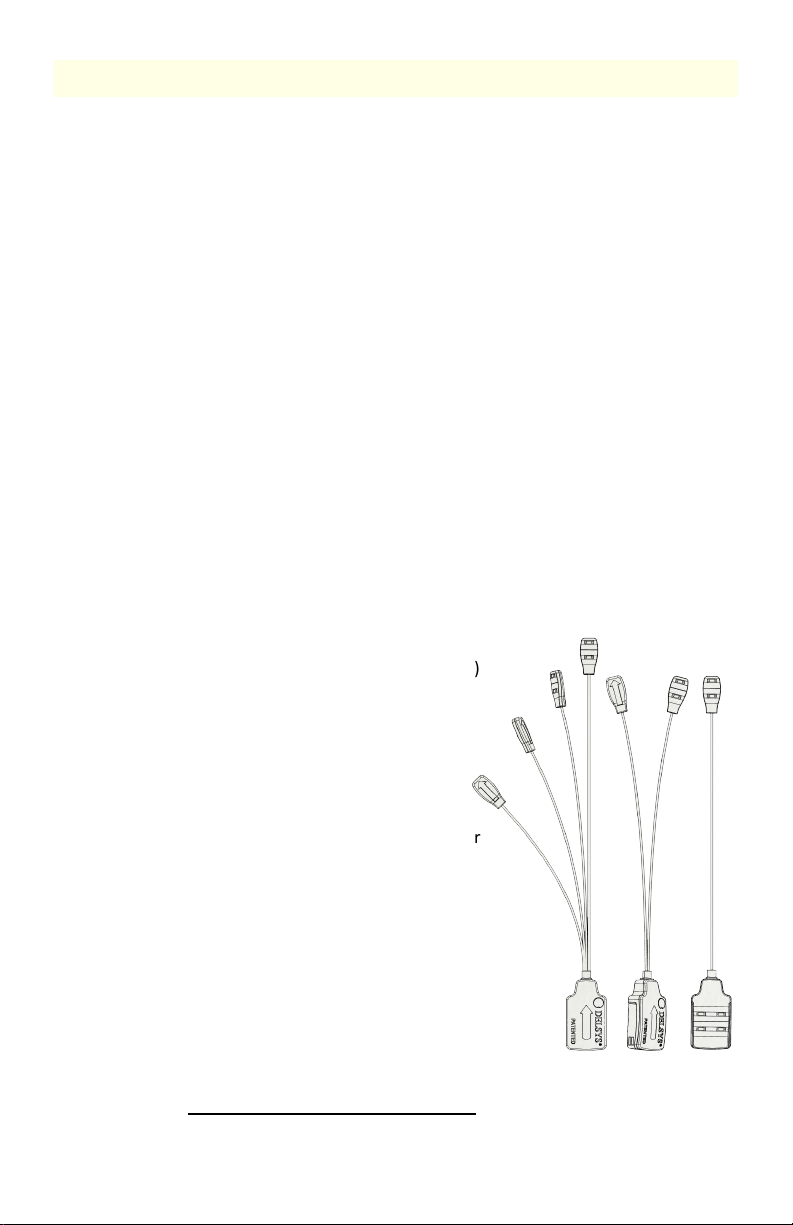
Trigno Quattro, Duo and Mini Sensor Features
The Trigno family of minihead sensors are capable of detecting four (“Quattro”),
two (“Duo”) or one (“Mini”) EMG signals with each head. Each Sensor is
equipped with the following capabilities and design features:
•Configurable bandwidth 20-450 Hz or 10 – 850Hz
•built-in 9-axis inertial measurement unit (IMU)
•onboard RMS and Mean calculations
•onboard orientation calculation
•software selectable operational modes
•inter-sensor latency < 1 sample period
•wireless transmission range 20+m1
•self-contained rechargeable battery
•battery charge monitoring and status indicator
•environmentally sealed enclosure
•low power mode
•auto shutoff
•internal magnetic switch
•LED User Feedback
•Four EMG detection locations (“Quattro”)
•Two EMG detection locations (“Duo”)
•One EMG detection location (“Mini”)
1. Communication distance is dependent on the RF operating environment.
Quattro
Duo
Mini

8 MAN-039-1-1
Differential EMG Sensing
Trigno sensors support, low noise, high fidelity sensing head for detecting EMG
(electromyographic) biofeedback signals from the surface of the skin when
muscles contract. The sensor bandwidth can be selected between 10-850Hz or
20-450 Hz and the input range of the sensor can be selected between 22mV or
11mV depending on user needs. Quattro and Duo sensors can be used to look
at more than one muscle or different regions of the same muscle at the same
time, from the single sensor.
Inertial Measurement Unit
Trigno sensors have a built-in 9 DOF inertial measurement unit which can relay
acceleration, rotation and earth magnetic field (compass) information. Users
can use this information to discern movement activity time-synchronized with
the EMG signals. One of 4 ranges can be selected for each sensor to span ±2g
to ±16g for accelerometer outputs and ±250°/s to ±2000°/s for gyroscope
outputs. The sensor is capable of estimating orientation in 3D space from the 9
channels of information.
Dual Mode “BLE-Base” Communication
Trigno sensors are capable of communication with a PC-connected Base station
using the Trigno custom wireless communication protocol, or with Android
devices using the Bluetooth Low Energy (BLE) industry standard protocol. Note
that the information bandwidth when operating over Bluetooth is limited by
the Bluetooth protocol and the host device capabilities.
Wireless Communication
The Trigno wireless communication scheme offers robust data transmission for
up to four quattro sensors operating in full bandwidth mode, with a nominal
distance of 20m. Under optimal environmental conditions (no RF path
obstructions or interfering sources), this nominal distance can be notably
superseded. Up to 16 sensors (64 EMG channels if using Quattro) can be
serviced by the system depending on data sampling requirements.
Data Synchronization
Data from each sensor and from each channel within a sensor are time
synchronized over the Trigno wireless communication protocol so no time skew
between data exists. A maximum of 16 sensors can stream data to a host base
station at one time. These features are available only when communicating with
the PC-connected Base Station; the Bluetooth/BLE protocol does not guarantee
latency.
Rechargeable Battery
Sensors contain a sealed rechargeable lithium polymer battery for continuous
use which can be extended when making use of low power modes. Actual
duration will depend on usage conditions, which are expected to vary between
2 to 6 hours of performance. Charge status is conveniently reported through
the wireless communication protocol.
Trigno Quattro, Duo, Mini EMG Sensor User’s Guide 9
Sealed Enclosure
The environmentally sealed enclosure protects the electronics from the ingress
of liquids and other environmental elements and provides a high standard of
user safety and durability.
Internal Magnetic Switch
The Trigno sensors are equipped with an internal magnetic switch which is used
to turn the sensors “on” and to perform RF pairing operations. To activate the
internal magnetic switch, the sensor must be placed on the magnet lock label
located on the Base Station charging cradle. The internal magnetic switch will
only react when the sensors are undocked from the charger or when the
software is performing an RF pairing operation. Exposure to any magnetic fields
outside of these 2 qualifying conditions will be ignored by the sensor. The
internal magnetic switch is a feature which removes the need for a mechanical
button and improves sensor durability and performance. Common household
magnets can be used to perform these functions as well.
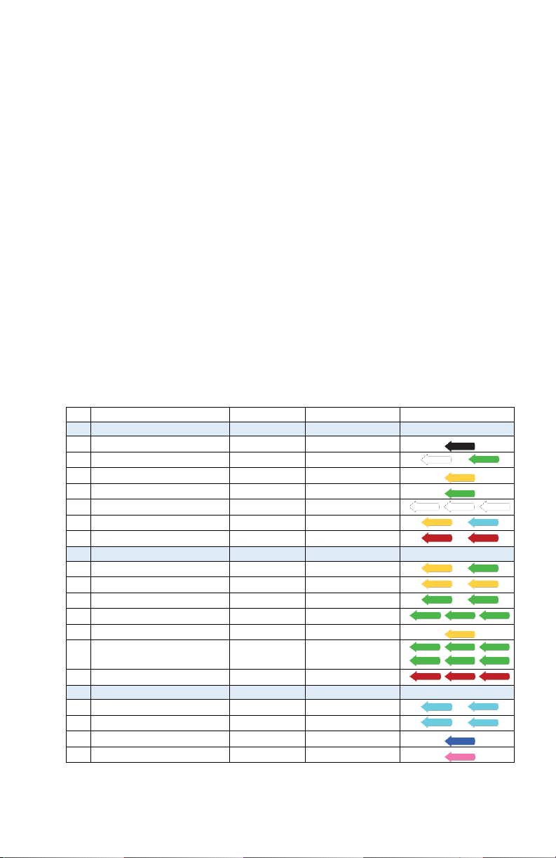
Sensor LED Feedback States
Trigno Avanti sensors indicate their status through various LED Arrow colors
and blink patterns as indicated in the table below. Each of these states is
described in subsequent sections of this User Guide.
State
Color
Pattern
Arrow Display
Common States
1
Power Off
Off
none
2
Power On/Activate
White/Green
fade
/
3
Charging
Amber
solid
4
Charge Complete
Green
solid
5
Identification Mode
White
rapid flash
/ /
6
Scan (Startup)
Amber/Cyan
slow flash
/
7
Power Up Error
Red
slow flash
/
Trigno RF Mode
8
Scan (Base)
Amber/Green
Slow flash
/
9
Low Power Scan (Base)
Amber
Occasional Flash
/
10
Data Collection (Base)
Green
slow flash
/
11
Configuration Change (Base)
Green
rapid flash (3x)
/ /
12
Pairing (Base)
Amber
solid
13 Pairing Success (Base) Green rapid flash (≥6x)
/ /
/ /
14
Pairing Fail (Base)
Red
double flash(≥3x)
/ /
BLE Mode
15
Advertise (BLE)
Cyan
Slow flash
/
16
Low Power Advertise (BLE)
Cyan
occasional flash
/
17
Data Collection (BLE)
Blue
slow flash
18
Idle (BLE)
Magenta
slow flash
Table 1: Sensor LED functions.

10 MAN-039-1-1
LED State Descriptions
1) Power Off: No LED arrow activity is present when the sensor is off.
2) Power On: When undocked, the sensor illuminates white and fades to
black. A magnetic field will turn the sensor on within 6 seconds, otherwise
the arrow fades to dark and sensor turns off.
3) Charging: Sensor Charging in the Trigno Base Station is denoted by
continuous amber LED arrow illumination
4) Charge Complete: Once the internal sensor battery has been fully
recharged, the LED arrow illuminates to continuous green.
5) Identification Mode: The arrows blink white upon this software command
so that it can be easily identified and located.
6) Startup Scan: upon power-up the sensor actively searches for a host to
connect to (PC Base Station or BLE tablet).
7) Power Up Error: Sensor fails self-check on power up
8) Scan (Base): Sensor was previously paired and is scanning for the active
base station.
9) Low Power Scan (Base): Sensor was previously paired and has been
scanning for the active base station for more than 5 minutes.
10) Data Collection (Base): Data from sensor are streaming to a paired PC-
connected base station.
11) Configuration Change (Base): Sensor acknowledges change in
configuration sensor from host base station.
12) Pairing (Base): Sensor is performing a pair operation with the base host.
13) Pairing Success (Base): Sensor successfully completes a pair operation with
the Base Station host.
14) Pairing Fail (Base): The pair operation did not complete successfully with
the Base Station host.
15) Advertise (BLE): Sensor is broadcasting to connect with a BLE host.
16) Low Power Advertise (BLE): Sensor is broadcasting to connect with a BLE
host for more than 5 minutes.
17) Data Collection (BLE): Sensor is sampling and streaming data to BLE host.
18) Idle (BLE): Sensor is waiting for a Bluetooth BLE command.

Trigno Quattro, Duo, Mini EMG Sensor User’s Guide 11
Getting Started with the Trigno Sensor
Please refer to the Trigno System User guide for key
operational details regarding the base station, sensor charging,
and initiating the sensor.
Configuring the Trigno Quattro/Duo/Mini Sensors
Once paired to the system, EMG data and IMU data from the sensor can be
configured through the software in the following ways:
Electromyographic (EMG) Sensing Ranges
Input Range
1
11 mV
or
22 mV
Bandwidth120-450 Hz or 10-850 Hz
RMS Window (optional)
4
100ms
Inertial Measurement Unit (IMU) Ranges
Accelerometer2±2 gor ±4 gor ±8 gor ±16 g
Accelerometer Bandwidth
2
24Hz - 470 Hz
Gyroscope
2
±250 dps
or
±500 dps
or
±1000 dps
or
±2000 dps
Gyroscope Bandwidth
2
24 Hz - 360 Hz
Orientation310 Hz
1EMG range, bandwidth selection and sampling rate are configured by the software.
2Accelerometer and gyroscope range, bandwidth and sampling rate are configured by
the software.
3Note that the magnetometer has a fixed range and a fixed bandwidth.
4An onboard RMS calculation can be invoked to reduce data transmission rates and
maximize bandwidth resources.
Using the Analog Outputs (if Equipped)
The Trigno System provides simultaneous analog signal reconstruction of data
being detected by all active sensors. These signals are made available on the
68-pin connectors located on the Base Station and range cover the +/-5V range.
Analog outputs are engaged through software and are only available for specific
sensor sampling configurations as stated in the sections below:
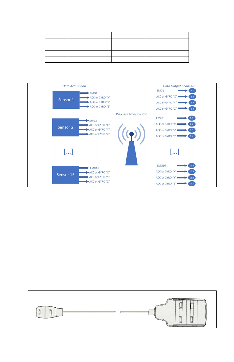
Quattro Analog Output Configuration
Sensor
Analog Output
Sampling Rate
Data Type
Bandwidth
1
Ch. 1.1,5.1,9.1,13.1
1926 sa/sec
EMG
20-450 Hz
2
Ch. 2.1,6.1,10.1,14.1
1926 sa/sec
EMG
20-450 Hz
3
Ch. 3.1,7.1,11.1,15.1
1926 sa/sec
EMG
20-450 Hz
4
Ch. 4.1,8.1,12.1,16.1
1926 sa/sec
EMG
20-450 Hz
Table 2: “Quattro” Analog Output signal details. Note that sampling rates are
approximate; please refer to specification table for precise sampling periods.

12 MAN-039-1-1
Figure 1: “Quattro” Analog Output Data Flowchart
Duo Analog Output Configuration
Sensor
Analog Output
Sampling Rate
Data Type
Bandwidth
1
Ch. 1.1,5.1
1926 sa/sec
EMG
20-450 Hz
2
Ch. 2.1,6.1
1926 sa/sec
EMG
20-450 Hz
3
Ch. 3.1,7.1
1926 sa/sec
EMG
20-450 Hz
4
Ch. 4.1,8.1
1926 sa/sec
EMG
20-450 Hz
5
Ch. 9.1,13.1
1926 sa/sec
EMG
20-450 Hz
6
Ch. 10.1,14.1
1926 sa/sec
EMG
20-450 Hz
7
Ch. 11.1,15.1
1926 sa/sec
EMG
20-450 Hz
8
Ch. 12.1,16.1
1926 sa/sec
EMG
20-450 Hz
Table 3: “Duo” Analog Output signal details. Note that sampling rates are approximate;
please refer to specification table for precise sampling periods.
Figure 2: “Duo” Analog Output Data Flowchart
Trigno Quattro, Duo, Mini EMG Sensor User’s Guide 13
“Mini” Analog Output Configuration
Sampling Rate
Data Type
Bandwidth
Ch. x.1
1926 sa/sec
EMG
20-450 Hz
Ch. x.2
148 sa/sec
ACC or Gyro X
DC-50 Hz
Ch. x.3
148 sa/sec
ACC or Gyro Y
DC-50 Hz
Ch. x.4
148 sa/sec
ACC or Gyro Z
DC-50 Hz
Table 4: “Mini” Analog Output signal details. Note that sampling rates are approximate;
please refer to specification table for precise sampling periods.
Figure 3: “Mini” Analog Output Data Flowchart
**Refer to the Trigno System User Guide for more information on Analog Output
Operation.**
Placing the Trigno Sensor on the Skin
Trigno Quattro, Duo and Mini Sensors consist of a main sensor body and four,
two or one cabled detection head(s) respectively. The sensor heads should be
placed near the centroid of the muscle to detect the maximum amount of EMG
activity. The sensor body should be affixed in a convenient nearby location to
provide a detection reference point. The sensor body and sensor head are
easily attached to the skin using the Delsys Adhesive Sensor Interfaces. The
sensor arrow on the top side should be oriented parallel to the direction of the
muscle fibers.
Figure 6. The EMG sensor head must be positioned overtop of the muscle of interest. The
reference contacts can be positioned in a convenient nearby location.
EMG contacts
reference contacts

14 MAN-039-1-1
Cleaning the Sensor Site
Prior to affixing the Trigno sensor on the surface of the skin, the sensor site for
the reference contacts and the EMG detection contacts must be properly
cleaned to remove dry dermis and any skin oils. Wiping the skin prior to sensor
application helps ensure a high-quality signal. If excessive hair is present, it will
also be necessary to shave the site. In cases where the skin is excessively dry, it
may be useful to dislodge dry skin cells by dabbing the site with medical tape.
The dry cells will attach the tape’s adhesive when it is removed. Be sure to wipe
with isopropyl alcohol to remove any adhesive residue that may remain.
Applying the Trigno Adhesive Skin Interfaces
Trigno System are supplied with specially-designed adhesive interfaces to
simplify sensor attachment. These hypo-allergenic interfaces are manufactured
from medical grade adhesive approved for dermatological applications. Usage
of the interface promotes a high quality electrical connection between the
sensor bars and the skin, minimizing motion artifacts and the ill-effects of line
interference. To ensure a strong bond with the skin, it is advised to remove
excessive hair and wipe the skin area and the EMG Sensor with isopropyl
alcohol to remove oils and surface residue. Allow the skin to dry completely
before applying the interfaces.
Adhesive Sensor Interfaces are for single use only. Discard after
using. Reseal storage bag to maintain freshness.
Immediately discontinue use if skin irritation or discomfort occurs.
Patients with sensitive skin may experience temporary redness
and irritation.
Do not use on Patients with allergies to silver.
Do not apply over open wounds or irritated skin.
Trigno Quattro, Duo, Mini EMG Sensor User’s Guide 15
Maintenance and Care
Trigno Sensors
Trigno sensor are encased in a sealed polycarbonate enclosure. The following
points should be kept in mind when handling the sensors.
•All sensors should be visually inspected before each use to ensure that
no mechanical deterioration has occurred.
•The sensors can be cleaned with isopropyl alcohol swabs. Ensure that
the sensor contacts remain clean at all times for proper operation.
•While the sensors are sealed and are water-resistant, these should
never be completely submerged in any liquid.
•The sensor contacts are made of pure silver and are quite soft. Care
should be taken to preserve the integrity of these contacts. Do not
scrape or dent these contacts.
Handle the sensors with care: do not drop them on the ground or
step on them.
Do not submerge the sensors in any liquid under any circumstance.
Do not pull the cable as this will result in damage.
The sensors contain sensitive electronic circuitry. Static discharges
and intense electro-magnetic fields should be avoided to prevent the
risk of irreparable damage to the sensors.

16 MAN-039-1-1
Specifications
Physical Specifications
Dimension (Body)
27 x 46 x 13 mm
Dimension (Head)
23 x 30 x 7 mm
Cable Length “Quattro”
254 mm, 229 mm, 203 mm, 178 mm
Cable Length “Duo”
254 mm
Cable Length “Mini”
203 mm
Mass (“Quattro”, “Duo”, “Mini”)
25g, 21g, 19g
Temperature Range(1)
5 - 45 degrees Celsius
EMG Contact Dimensions
5 x 1 mm
Contact Material(2)
99.99% silver
1) Exposure beyond these temperature limits may damage the rechargeable battery.
2) Sensor skin contacts are made from pure silver and should not be used if allergic reactions to silver are expected or found to occur.
Electrical Specifications
RF Frequency Band
2400-2483 MHz (ISM band)
EMG Signal Input Range
11mV / 22mV r.t.i.
EMG Signal Bandwidth
20-450 Hz / 10-850 Hz
Accelerometer Range
±2g, ±4g, ±8g, ±16g
Accelerometer Bandwidth
24 Hz – 246 Hz (configurable in software)l
Gyroscope Range
±250 dps, ±500 dps. ±1000dps, ±2000dps
Gyroscope Bandwidth
24Hz – 361 Hz (configurable in software)
Magnetometer Range
±4900 uT
Magnetometer Bandwidth
50 Hz
Inter-Sensor Delay
< 1 sample period (Base Station only)
Intra-Channel Delay
< 1-2 sample period

Trigno Quattro, Duo, Mini EMG Sensor User’s Guide 17
“Quattro” EMG Measurement Data Modes
Configuration ID
# Data Slots1
#EMG Channels
EMG Sampling Period
2(ms)
EMG Sampling Rate
2(sa/sec)
RMS Window
3(ms)
RMS Sampling Period2(ms)
RMS Update Rate
4
(sa/sec)
EMG Bandwidth
5(Hz)
EMG Input Range6(mV)
EMG Resolution Depth7(bits)
ACC Sampling Period
2(ms)
ACC Sampling Rate2(sa/sec)
ACC Bandwidth
8
(Hz)
ACC Range
7(g)
ACC Resolution7(bits)
Gyro Sampling Period
2(ms)
GYRO Sampling Rate2(sa/sec)
GYRO Bandwidth
8(Hz)
Gyro Range
7(dps)
Gyro Resolution7(bits)
1 2 4 0.9 1111 -- -- -- 20-450
11
22
16
-- -- -- -- -- -- -- -- -- --
2 4 4 0.45 2222 -- -- --
20-450
10-850
11
22
16
-- -- -- -- -- -- -- -- -- --
1)
The Trigno System is designed with 16 data slots for wireless transmission. Sensors can occupy up to 4 slots
depending on the sampling rate settings.
2)
Sampling period is the precise time elapse between samples in milliseconds. The sampling rate is a rounded
expression of 1/”sampling period” expressed as samples/second (sa/sec).
3)
Analog EMG Sensor Butterworth filter bandwidth: 2 pole high pass corner, 4 pole low pass corner in Hz.
4)
EMG signal input range of sensor in millivolts.
5)
sensor resolution depth across input range.
Denotes raw EMG signal acquisition.
18 MAN-039-1-1
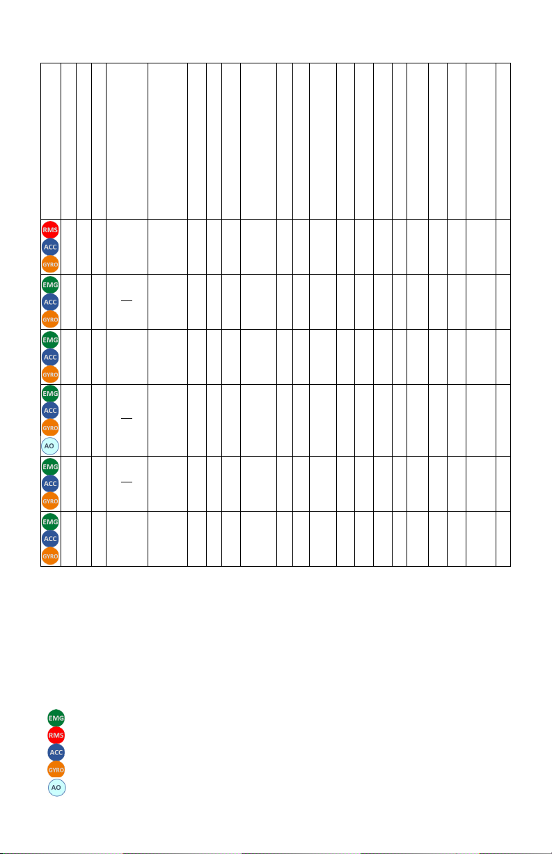
“Quattro” Inertial Measurement Data Modes
Configuration ID
# Data Slots1
#EMG Channels
EMG Sampling Period
2(ms)
EMG Sampling Rate
2(sa/sec)
RMS Window3(ms)
RMS Sampling Period2(ms)
RMS Update Rate
4(sa/sec)
EMG Bandwidth
5(Hz)
EMG Input Range6(mV)
EMG Resolution Depth7(bits)
ACC Sampling Period
2(ms)
ACC Sampling Rate2(sa/sec)
ACC Bandwidth
8
(Hz)
ACC Range
7(g)
ACC Resolution7(bits)
Gyro Sampling
Period2(ms)
GYRO Sampling Rate2(sa/sec)
GYRO Bandwidth
8(Hz)
Gyro Range
7(dps)
Gyro Resolution7(bits)
3 1 4 0.5 2000
100
4.5
222
20-450
11
22
16
13.5 74 24
±2
±4
±8
±16
16
13.5
74 24
±250
±500
±1000
±2000
16
4 2 4 27
26 963 -- -- -- 20-450
11
22
16
6.75
148
50
±2
±4
±8
±16
10
6.75
148
50
±250
±500
±1000
±2000
10
5 4 4 0.5 2000 -- -- -- 20-450
10-850
11
22
16
6.75
148
50
±2
±4
±8
±16
16
6.75
148
50
±250
±500
±1000
±2000
16
6 4 4 27
52 1926 -- -- -- 20-450
10-850
11
22
16
4.5
222
111
±2
±4
±8
±16
16
6.75
148
50
±250
±500
±1000
±2000
16
7 4 4 27
46 1704 -- -- -- 20-450
11
22
16
3.375
296
111
±2
±4
±8
±16
16
2.7
370
151
±250
±500
±1000
±2000
16
8 4 4 0.9 1111 -- -- -- 20-450
11
22
16
1.35
741
246
±2
±4
±8
±16
16
1.35
741
361
±250
±500
±1000
±2000
16
1)
The Trigno System is designed with 16 data slots for wireless transmission. Sensors can occupy up to 4 slots
depending on the sampling rate settings.
2)
Sampling period is the precise time elapse between samples in milliseconds. The sampling rate is a rounded
expression of 1/”sampling period” expressed as samples/second (sa/sec).
3)
RMS window is the period of raw signal that is captured and process to produce singular RMS value.
4)
RMS update rate is the rate at which the RMS calculation is updated, expressed as samples/sec (sa/sec).
5)
Analog EMG Sensor Butterworth filter bandwidth: 2 pole high pass corner, 4 pole low pass corner in Hz.
6)
EMG signal input range of sensor in millivolts.
7)
sensor resolution depth across input range.
8)
IMU bandwidth determined by onboard digital low pass filter
9)
Accelerometer signal input range in “g” (i.e. 9.8 m/s2)
10)
Gyroscope angular rate input range in degrees per second (dps).
Denotes raw EMG signal acquisition.
Denotes onboard RMS calculation of the EMG signal.
Denotes onboard 3 DOF accelerometer data.
Denotes onboard 3 DOF gyroscope data.
Denotes analog output supported mode.
Trigno Quattro, Duo, Mini EMG Sensor User’s Guide 19
“Quattro” Orientation Measurement Data Modes
Denotes raw EMG signal acquisition.
Denotes onboard RMS calculation of the EMG signal.
Denotes onboard calculation of orientation fused from 3 DOF accelerometer, 3 DOF gyroscope and 3 DOF
magnetometer data.
Configuration
ID
# Data Slots
1
# EMG Channels
EMG Sampling Period
2(ms)
EMG Sampling Rate
2(sa/sec)
RMS Window
3(ms)
RMS Sampling Period
2(ms)
RMS Update Rate
4(sa/sec)
EMG Bandwidth
5(Hz)
E
MG Input Range
6(mV)
EMG Resolution Depth
7(bits)
Orientation
Sampling Period
2(ms)
Orientation Sampling Rate
2(sa/sec)
Orientation Resolution
8(bits)
9 1 4 0.5 2000 100
4.5
222 20-450 11
22 32 13.5 74 20
10 2 4 27
26 963 -- -- -- 20-450 11
22 16 13.5 74 28
11 4 4 0.5 2000 -- -- -- 20-450
10-850
11
22 16 13.5 74 32
1)
The Trigno System is designed with 16 data slots for wireless transmission. Sensors can occupy up to 4 slots
depending on the sampling rate settings.
2)
Sampling period is the precise time elapse between samples in milliseconds. The sampling rate is a rounded
expression of 1/”sampling period” expressed as samples/second (sa/sec).
3)
RMS window is the period of raw signal that is captured and process to produce singular RMS value.
4)
RMS update rate is the rate at which the RMS calculation is updated, expressed as samples/sec (sa/sec).
5)
Analog EMG Sensor Butterworth filter bandwidth: 2 pole high pass corner, 4 pole low pass corner in Hz.
6)
EMG signal input range of sensor in millivolts.
7)
sensor resolution depth across input range.
8)
Orientation vector output resolution in bits. Orientation is expressed in quaternions and is performed on the sensor.

20 MAN-039-1-1
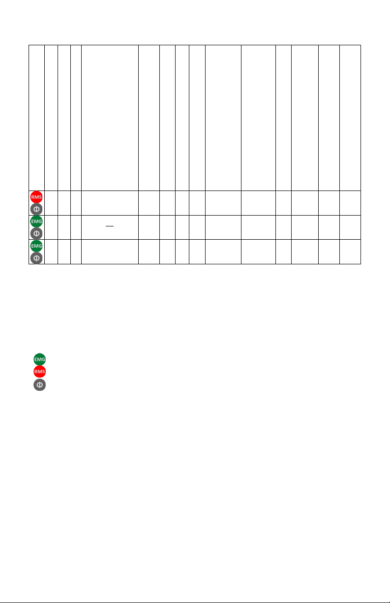
“Duo” EMG Measurement Data Modes
Configuration ID
# Data Slots1
# EMG Channels
EMG Sampling Period
2(ms)
EMG Sampling Rate
2(sa/sec)
RMS Window
3(ms)
RMS Sampling Period
2(ms)
RMS Update Rate
4(sa/sec)
EMG Bandwidth
5(Hz)
EMG Input Range6(mV)
EMG Resolution Depth7(bits)
ACC Sampling Period
2(ms)
ACC Sampling Rate2(sa/sec)
ACC Bandwidth
8(Hz)
ACC Range
7(g)
ACC Resolution7(bits)
Gyro Sampling Period
2(ms)
GYRO Sampling Rate2(sa/sec)
GYRO Bandwidth
8
(Hz)
Gyro Range
7(dps)
Gyro Resolution7(bits)
1 1 2
27
28
1037 -- -- -- 20-450
11
22
16
-- -- -- -- -- -- -- -- -- --
2 2 2
27
58
2148 -- -- --
20-450
10-850
11
22
16
-- -- -- -- -- -- -- -- -- --
1)
The Trigno System is designed with 16 data slots for wireless transmission. Sensors can occupy up to 4 slots
depending on the sampling rate settings.
2)
Sampling period is the precise time elapse between samples in milliseconds. The sampling rate is a rounded
expression of 1/”sampling period” expressed as samples/second (sa/sec).
3)
RMS window is the period of raw signal that is captured and process to produce singular RMS value.
4)
RMS update rate is the rate at which the RMS calculation is updated, expressed as samples/sec (sa/sec).
5)
Analog EMG Sensor Butterworth filter bandwidth: 2 pole high pass corner, 4 pole low pass corner in Hz.
6)
EMG signal input range of sensor in millivolts.
7)
sensor resolution depth across input range.
8)
IMU bandwidth determined by onboard digital low pass filter
9)
Accelerometer signal input range in “g” (i.e. 9.8 m/s2)
10)
Gyroscope angular rate input range in degrees per second (dps).
Denotes raw EMG signal acquisition.
This manual suits for next models
2
Table of contents
Other Delsys Accessories manuals


