Delsys TRIGNO User manual

TRIGNOTM EMG System
Copyright © Delsys Incorporated
Delsys Logo and EMGworks are
Registered Trademarks of Delsys Inc.
MAN-016-1-1
Snap Lead Sensor User’s Guide


Trigno™ Snap Lead Sensor User’s Guide
Table of Contents
Important Information 4
Intended Use 4
Technical Service and Support 4
Warnings and Precauons 5
Device Informaon 6
Disclaimer 8
System Requirements 8
Snap Lead Sensor Overview 9
Using the Sensors 10
Charging the Sensors 10
Sensor Pairing 11
Smart Sensor Features 12
Working with the Snap Lead Sensors 13
Maintenance and Care 15
Specications 17
Trigno™ Snap Lead Sensor User’s Guide
4
Important Information
Intended Use
e TrignoTM Wireless EMG Systems are battery-powered biofeed-
back devices that enable researchers and clinicians to acquire EMG
and related signals from subjects for biofeedback purposes. ey are
intended for relaxation training and muscle reeducation. Interpre-
tation of the EMG and supporting signals by a qualied individual
is required.
Rx ONLY
DO NOT USE on Patients with implanted electronic devices of
any kind, including cardiac pace-makers or similar assistive devices,
electronic infusion pumps, and implanted stimulators.
DO NOT USE on irritated skin or open wounds.
DO NOT USE on Patients with allergies to Silver.
DO NOT USE in critical care applications.
Technical Service and Support
For information and assistance visit our web site at:
www.delsys.com
Contact us at:
telephone: (508)-545-8200
email: support@delsys.com

5
TrignoTM EMG System
Warnings and Precautions
Consult all accompanying documents for precautionary statements
and other important information.
Consult accompanying user’s guide for detailed instructions.
Keep the device dry. e device is not waterproof and should not be
submerged under any circumstance. e ingress of liquids may com-
promise the safety features of the device. e device is not intended
for use under high sweat conditions. Situations which may result in
the entrapment of sweat around the sensors must be avoided.
Handle with care. Trigno™ sensors and instruments are precision de-
vices and not designed for excessively rugged use. Carefully inspect
devices prior to each use to ensure that no mechanical deterioration
has occurred.
Sensitive electronic device. Avoid static discharges. Do not operate
or store near strong electrostatic, electromagnetic, magnetic or ra-
dioactive elds. Interference from external sources may decrease the
signal-to-noise ratio or result in corrupted data.
Connect only to Delsys-approved devices.
Connecting a patient to high-frequency surgical equipment while
using Delsys EMG systems may result in burns at the site of the
EMG sensor contacts.
Immediately discontinue device use if skin irritation or discomfort
occurs.
Immediately discontinue device use if a change in the device’s per-
formance is noted. Contact Delsys technical support for assistance.
Delsys Inc. guarantees the safety, reliability, and performance of the
equipment only if assembly, modications and repairs are carried
out by authorized technicians; the electrical installation complies
with the appropriate requirements; and the equipment is used in ac-
cordance with the instructions for use.
Trigno™ Snap Lead Sensor User’s Guide
6
Device contains a Lithium-Polymer battery. Do not damage, crush,
burn, freeze, heat or otherwise mishandle the device. Recharge only
with the approved power supply and recharger. Sensors should be
charged at least once every 3 months to prevent battery damage
from excessive self discharge. Extended periods in the discharged
state may damage the internal lithium polymer cell.
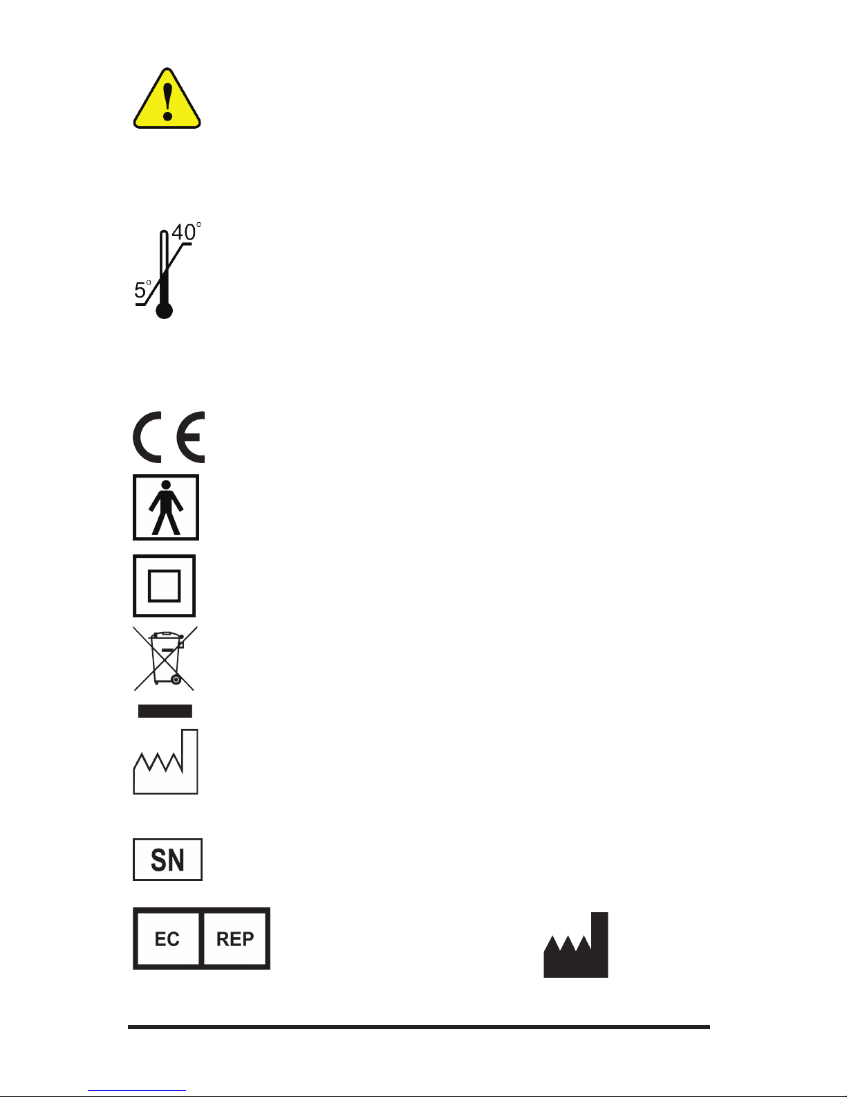
Trigno™ Systems should be stored and operated between 5 and 40
degrees Celsius due to the presence of an internal Lithium Polymer
rechargeable cell. Storing or operating the device, and consequently
the cell, outside of this temperature range may compromise the in-
tegrity and the safety features of the cell.
Device Information
Complies with Requirements put forth by the Medical Device Di-
rective 93/42/EEC. Class I device, Annex VII.
Type BF device (IEC 60601-1).
Isolated device, (Class II, IEC 60601-1)
Do not dispose this product with house waste. Contact Delsys Inc.
for instructions on responsibly disposing this device. is product
should not be mixed with other commercial wastes.
Date of Manufacturing (appears on device)
Serial Number (appears on device)
EMERGO EUROPE
Prinsessegracht 20
2514 AP The Hague
The Netherlands
Authorized Representative Manufacturer
DELSYS INC.
23 Strathmore Rd.
Natick, MA 01760
USA
7
TrignoTM EMG System
FCC ID: W4P-SP-W01 (Trigno™ Sensor)
FCC ID: W4P-SP-W05 (Trigno™ Sensor)
is device complies with Part 15 of the FCC Rules and Industry
Canada’s RSS-210 License Exempt Standards. Operation is sub-
ject to the following two conditions: (1) is device may not cause
harmful interference, and (2) this device must accept any interfer-
ence received, including interference that may cause undesired op-
eration.
is product complies with FCC OET Bulletin 65 radiation expo-
sure limits set forth for an uncontrolled environment.
Pursuant to Part 15.21 of the FCC Rules, any changes or modica-
tions to this product not expressly approved by Delsys Inc. might
cause harmful interference and void the FCC authorization to op-
erate this product.
To reduce potential radio interference to other users, the antenna
type and its gain should be so chosen that the equivalent isotropi-
cally radiated power (EIRP) is not more than that required for suc-
cessful communication.
is equipment has been tested and found to comply with the limits
for a Class B digital device, pursuant to Part 15 of the FCC Rules.
ese limits are designed to provide reasonable protection against
harmful interference in a residential installation. is equipment
generates, uses, and can radiate radio frequency energy and, if not
installed and used in accordance with the instructions, may cause
harmful interference to radio communications. ere is no guaran-
tee that interference,will not occur in a particular installation. If this
equipment does cause harmful interference to radio or television
reception, which can be determined by turning the equipment o
and on, the user is encouraged to try to correct the interference by
one or more of the following measures:
• Reorient or relocate the receiving antenna.
• Increase the separation between the equipment and receiver.
• Connect the equipment into outlet on a separate circuit.

Trigno™ Snap Lead Sensor User’s Guide
8
Disclaimer
DELSYS INC. makes no warranties, express or implied, as to the
quality and performance of this product including but not limited
to, any implied warranty of applicability for other than research
uses by qualied individuals. DELSYS INC. shall not be liable to
any person for any medical expenses or any direct or consequential
damages resulting from any defect, failure or malfunction, whether
a claim for such damages is based upon theory of warranty, contract,
tort or otherwise. No representative, agent, or licensed practitioner
is authorized to waive this disclaimer. DELSYS INC. makes no di-
agnosis or prescription by virtue of anything about this product.
System Requirements
e Trigno™ Snap Lead Sensor is designed to be used with Trigno™
Wireless EMG Systems.

9
TrignoTM EMG System
Delsys recommends to use Snap Lead sensors with care as motion ar-
tifact and cross-talk issues are commonly associated with these types
of wire-lead electrode sensors. Also, please be aware that large inter-
electrode distances may increase the EMG signal cross-talk from ad-
jacent and underlying muscles and could possible obscure the surface
EMG signal of inerest.
Snap Lead Sensor Overview
Figure 1. Snap Lead Sensor- The main body host 4 contacts
for establishing a local reference, and includes an on-board
±1.5g/±6g accelerometer.
Trigno™ Snap Lead Sensor User’s Guide
10
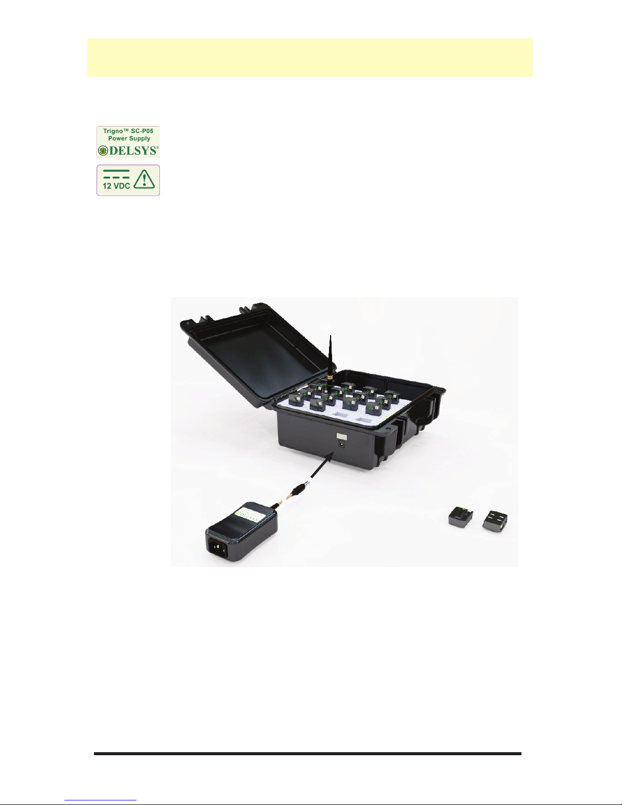
Charging the Sensors
Connect the Trigno™ power supply to the circular DC jack located
on the side of the Trigno™ Base/Recharge Station. Energize the power
supply by connecting it to a Mains outlet. Be sure to use the appro-
priate plug adapter for your location. Ensure that the Trigno™ sensors
are properly tted in the recharge pockets. e sensor LEDs will illu-
minate to amber during charging and green when charge is complete.
e recharge unit will periodically check sensors and apply a top-o
charge to ensure that the battery is kept at full capacity during ex-
tended periods of storage, as long as power is connected.
Figure 2. Connecng the SC-P05 power supply to the Sensor
Charge Staon.
Using the Sensors
11
TrignoTM EMG System
Sensor Pairing
Trigno™ sensors communicate with a custom wireless protocol that
links each sensor to the active Trigno™ network is linking process
is known as sensor “pairing”, and is initiated through the “Pair” com-
mand in EMGworks®.
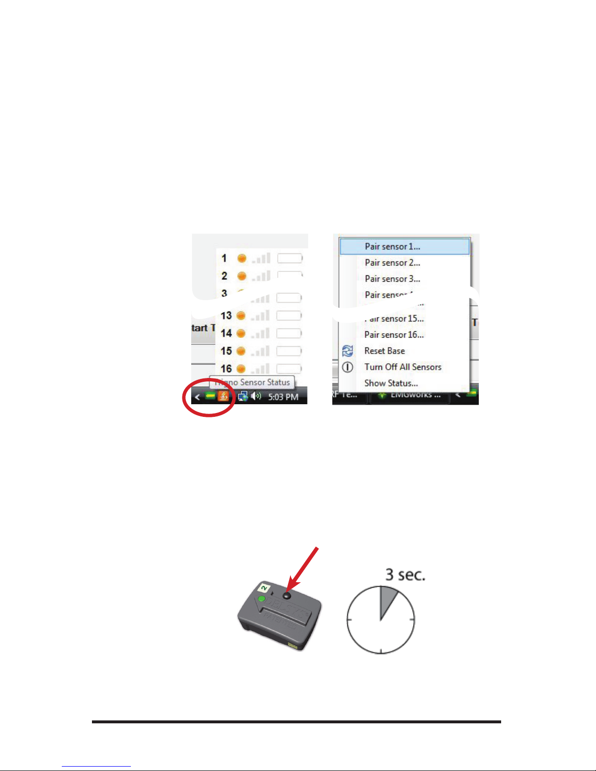
1. Turn sensor on by depressing the sensor button.
2. Initiate sensor pairing in soware.
When using EMGworks®, initiate pairing by right-clicking the Tri-
gno™ hardware icon in the system notication area, and selecting the
appropriate menu item.
Figure 3. Invoking the Pair command. Right click on the Trigno™
icon in the system tray (le) and select the desired channel to
pair to (right).
3. Complete the pairing process by depressing the desired sensor but-
ton for a minimum of 3 seconds. Successful pairing will result in 3
green LED ashes on the sensor, and a conrmation message in the
soware.
Figure 4. Pushing the sensor buon to complete the pairing
task.
Trigno™ Snap Lead Sensor User’s Guide
12
Trigno™ systems are shipped with all sensors appropriately paired.
Sensor pairing is typically needed in the following situations: a) if
sensors are being replaced within the network group, b) when the
communication frequency sets are changed, and c) aer a rmware
upgrade is performed.
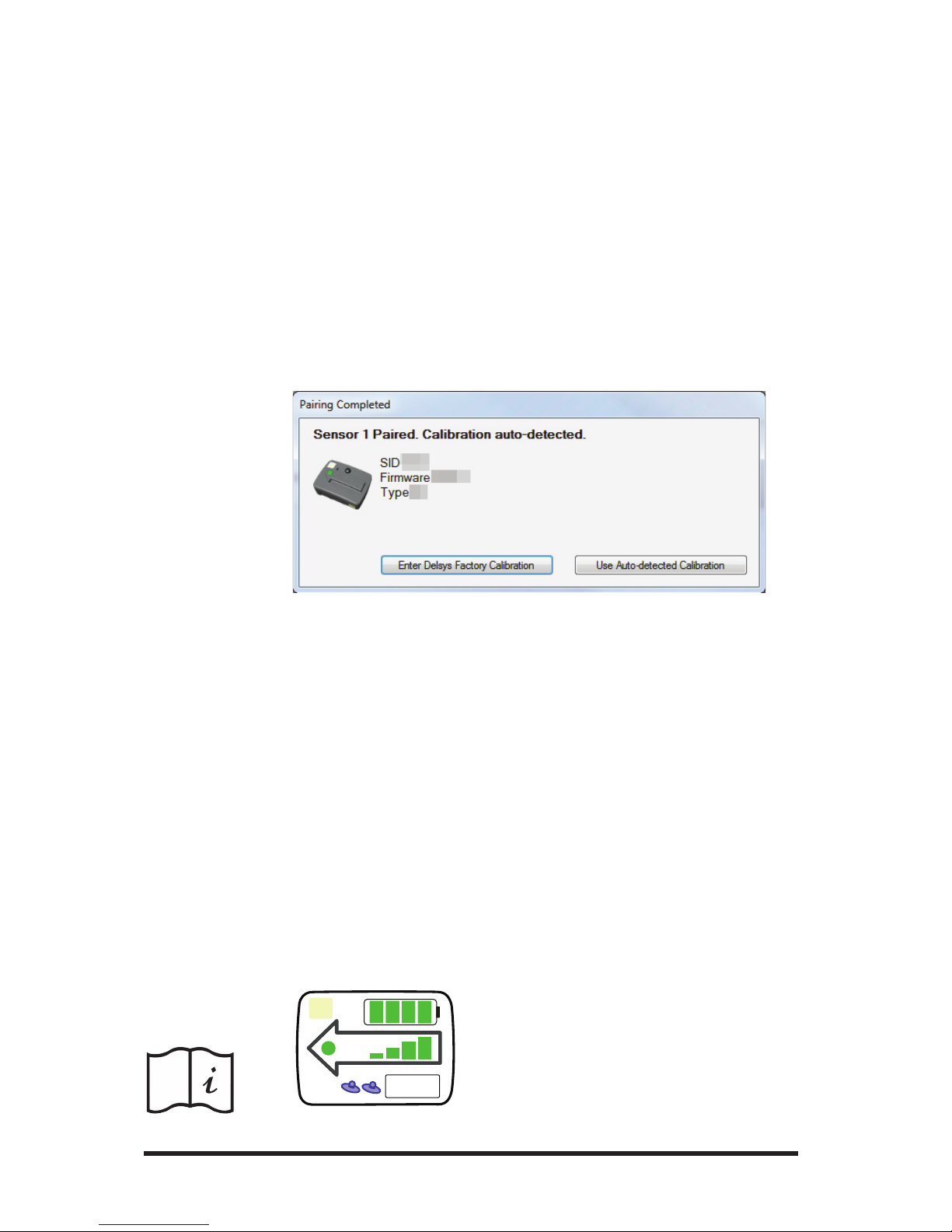
Upon pairing sensors, EMGworks® will present the option to enter a
“Delsys Factory Calibration” sequence or to use the “Auto-Detected
Calibration”. Select the “Auto-Detected Calibration” option unless
the sensor is specically supplied with a calibration key (this is not
common). Note that if the sensor is being paired for the rst time
with the base station, the choice will read “Use Default Calibration”
rather than “Use Auto-detected Calibration”.
Figure 5: The calibraon can be auto-detected, or manually re-
trieve..
Smart Sensor Features
Aer pairing, the association of sensors to the Trigno™ System is re-
tained for all future uses. Any conguration in EMGworks® can be
made to reect the last paired set of sensors by clicking the “Refresh
Smart Sensors” button in the “Add Sensors” pane in EMGworks®.
When data collection starts, the soware will verify that the sensors
currently communicating match those used in the conguration. If
there is a mismatch, cancel the recording and repair the sensors.
e Snap Lead EMG Sensor will appear with a unique icon shown
below in EMGworks once it has been properly paired and identied.
1
Pair
C
Figure 6. Trigno™ Snap Lead
Sensor icon appearing EMG-
works, idened as a type “J”
device. (Note that the icon may
appear dierent than shown.

13
TrignoTM EMG System
Please refer the Trigno™ EMG System User Guide for further details
on system and sensor operation.
Working with the Snap Lead Sensors
As with all EMG sensor technolgoy, the Trigno Snap Lead sensors
must be propoerly position above the muscle to to obtain a qualtiy
EMG signal. e snap electrodes must be placed to parallael to the
muscle ber direction for maximmal signal detection. Rotational
skew from this optimal orientation will diminish signal amplitude
and increase the potential for signal crosstalk.
e sensor body and its 4 silver contacts must be well-axed to the
skin to provide a quality signal reference point for the Snap Lead
EMG contacts. Use the Delsys SC-F03 four-slot adhesive skin inter-
face to adhere the sensor to the skin. ese interfaces are manufac-
tured from medical grade adhesive approved for dermatological ap-
Figure 7. The Snap Lead sensor top is marked with an arrow
which must be placed parallel to the muscle ber direcon in
order to properly detect an EMG Signal.

Trigno™ Snap Lead Sensor User’s Guide
14
plications. Usage of the interface promotes a high quality connection
between the sensor bars and the skin, minimizing motion artifacts
and the potential disturbances from line interference. Other methods
of skin attachment are not recommended.
Adhesive Sensor Interfaces are for single use only.
Immediately discontinue use if skin irritation or discomfort oc-
curs. All Adhesive Sensor Interfaces are for single use only. Dis-
card after using. Reseal storage bag to maintain freshness.
Prior to axing the EMG sensor on the surface of the skin, it is rec-
ommended to clean the area to remove dry dermis and skin oils. If
excessive hair is present, it may also be necessary to shave the site. In
cases where the skin is excessively dry, it may be useful to dislodge
dry skin cells by dabbing the site with medical tape. e dry cells will
attach the tape’s adhesive when it is removed. Be sure to wipe with
isopropyl alcohol to remove any adhesive residue that may remain.

15
TrignoTM EMG System
Maintenance and Care
Trigno™ sensors are encased in a sealed polycarbonate enclosure. e
following points should be kept in mind when handling the sensors.
• All sensors should be visually inspected before each use to ensure
that no mechanical deterioration has occurred.
• e sensors can be cleaned with 70% isopropyl alcohol swabs. En-
sure that the sensor contacts remain clean at all times for proper
operation.
• e sensors are not waterproof and should not be submerged in
any liquids under any circumstance. e ingress of liquids may
compromise the safety features of the device. ese devices are not
intended for use under high-sweat conditions, where the accumula-
tion or the entrapment of sweat can expose the sensor to sustained
levels of dampness.
• e sensor contacts are made of pure silver and are quite so. Care
should be taken to preserve the integrity of these contacts. Do not
scrape or dent these contacts.
• Handle the sensors with care: do not drop them on the ground or
step on them.
• e cables connecting the Snap Lead sensing element to the sensor
body is designed to be supple and unobtrusive while being worn.
Take care to never pull device by the cable, or excessively stress this
cable as this may result in cable damage. Inspect the device prior to
each use to ensure that not deterioration has occurred.
• Battery duration is a function of battery age and charge/discharge
conditions. Optimal battery performance is obtained when the
device is operated at room temperature. Excessive heating (above
40 deg. C) or excessive cooling (below 5 deg. C) may damage the
internal battery. Contact Delsys Technical support if the device is
exposed to temperatures outside of these limits.
• e device battery capacity is typically expected to decrease to 80%
of it’s original capacity aer 300 charge/discharge cycles. Batteries
will self-discharge with time if unused. Excessive self-discharging
may damage the battery. Periodically charge the sensors at least
once every 3 months, to extend battery life.
Trigno™ Snap Lead Sensor User’s Guide
16
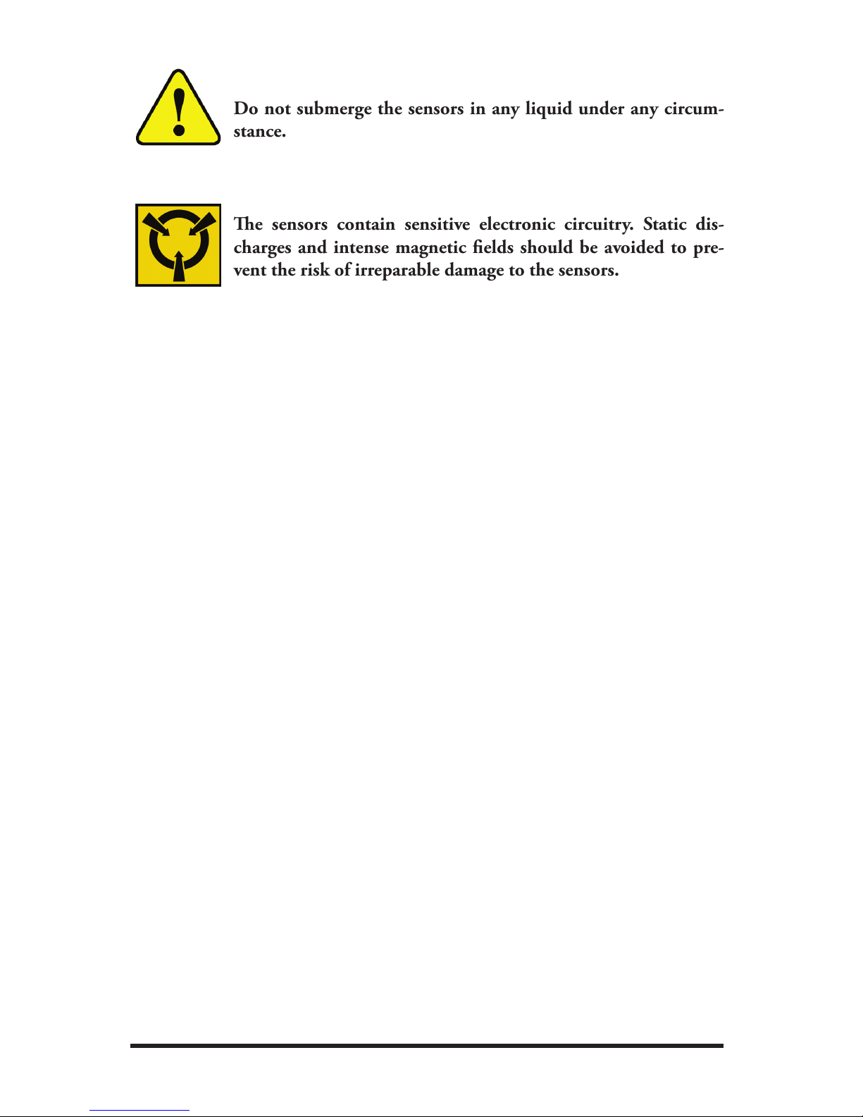
Do not submerge the sensors in any liquid under any circum-
stance.
e sensors contain sensitive electronic circuitry. Static dis-
charges and intense magnetic elds should be avoided to pre-
vent the risk of irreparable damage to the sensors.

17
TrignoTM EMG System
Specications
Typical Operating Range(1) 40 m
RF Frequency Band 2400-2483 MHz (ISM band)
Power Consumption <65 mW
Effective Radiated Power 9 mW
RF Protocol Proprietary
Enclosure Dimension (main sensor) 27 x 37 x 15 mm
Full-charge Operation Time(2) 8 hours (typical)
Recharge Time(3) <2.5 hours
Temperature Range(4) 5 - 40 degrees Celsius
Signal Range 11 mV (r.t.i)
EMG Channel Bandwidth 20 ± 5 Hz, >40 dB/dec
450 ± 50 Hz, >80 dB/dec
ACC Channels Bandwidths DC - 50 Hz ± 5 Hz, 20 dB/dec
EMG Channel Sampling Rate 1925.93 samples/sec
Accelerometer Sampling Rate 148.1 samples/sec/axis
EMG Channel Resolution Depth 20 ± 5 Hz > 40 dB/dec
450 ± 50 Hz > 80 dB/dec
Accelerometer Resolution Depth 0.016 ± 0.001 g/bit (at ± 1.5 g)
0.063 ± 0.005 g/bit (at ± 6 g)
EMG Channel Noise(5) <500 nV (rms), r.t.i.
Accelerometer Noise 0.004g (rms, ± 1.5g)
0.016g (rms, ± 6g)
(1) Range is characterized in open ofce environments. Interfering RF sources in the
2.4 GHz spectrum, as well as absorptive objects occluding the RF communication path
may degrade transmission distance. Stated range can be exceeded under favorable RF
conditions.
(2) Battery duration is a function of charge and discharge conditions. Optimal battery per-
formance is obtained when the device is operated at room temperature. Note that the
stated Operation Time reects the expected performance of a fully charged new battery
used in a sensor that is transmitting data. Operation Time is expected to decrease as a
function of charge cycles, and when the sensor is searching for a network.
(3) 80% of original battery capacity is maintained after 300 discharge/recharge cycles or
after 2 years if recharge cycles are less than 300. These values represent typical ex-
pectations under normal conditions. Actual performance will vary depending on usage
conditions.
(4) Operation beyond these temperature limits may damage the rechargeable battery.
(5) Input-referred noise is calculated as a root mean square over a 3 second window sam-
pled at 1926 kHz.

Trigno™ Snap Lead Sensor User’s Guide
18
This page has been intenonally le blank.
Other manuals for TRIGNO
5
Table of contents
Other Delsys Accessories manuals


