DELTA DORE PoE SW4 User manual

PoE SW4
FR Guide d’installation
EN Installation guide
DE Installationsanleitung
IT Guida di installazione
ES Manual de instalación
PL Instrukcja instalacji
NL Installatiegids

3
2
FR
Caractéristiques techniques
Interfaces Port RJ45 10/100 Mbps 5
Port prioritaire Port 1
Performance Stocker et transférer Supporté
Table MAC 1 k
Apprentissage MAC Auto-apprentissage
Capacité de
commutation
1 Gbps
Puissance PoE PoE standard IEEE 802.3af, IEEE 802.3at
Mode d’alimentation
PoE
Prend en charge l’alimentation 8 broches,
les broches 1,2,3,6 et les broches 4,5,7,8
peuvent être alimentées simultanément
Port PoE 1 - 2 - 3 - 4
Sortie de port Max. 30W
Sortie totale Max. 58W
Mode étendu Supporté
Classement
contre la foudre
Port 4KV
Alimentation protégée
contre la foudre
4KV
Alimentation
électrique
INPUT : 100-240VAC 50/60Hz 1,5A
OUTPUT : 51V DC, 1.25A
Température de
fonctionnement
0°C / 40°C
Humidité : 10% ~ 90%
sans condensation
Température de
stockage
-40 / 70°C
Humidité : 5% ~ 90%
sans condensation
Vitesse de
transmission
maximale
Ethernet: 10Mbps (Half Duplex) / 20Mbps
(Full Duplex) Fast Ethernet: 100Mbps (Half
Duplex) / 200Mbps (Full Duplex)
Réseau IEEE 802.3, IEEE 802.3u, IEEE 802.3af,
IEEE802.3at, IEEE 802.3x
1 - Présentation 4
2 - Contenu de l’emballage 4
3 - Description 5
3.1 Face avant: 5
3.2 Face arrière 5
4 - Préconisation d’installation 6
4.1 Pour assurer un fonctionnement optimal 6
4.2 Type de câble à utiliser 6
5 - Installation 7
5.1 Montage sur support 7
5.2 Montage en coffret VDI 7
5.3 Raccordement 8
5.4 Mode étendu 8
En raison de l’évolution des normes et du matériel, les caractéristiques indiquées par
le texte et les images de ce document ne nous engagent qu’après conrmation par nos
services.

5
4
FR
3 - Description
LINK/ACT
EXTEND
PWR
PoE MAX
LINK/ACT N/APOE STATUS
POE UPLINK
12 3 4 5
OFF ON
1 3 4
5
3
2 7 6
3.1 Face avant:
Voyant Status Description
1 - PWR
Allumé xe L’appareil est correctement connecté à l’alimentation
électrique.
Eteint L’appareil est mal connecté ou n’est pas connecté à
l’alimentation électrique.
2- PoE-MAX Allumé xe La puissance PoE atteint sa valeur limite inférieure (6W).
Clignotant La puissance PoE atteint son maximum (58W).
Eteint L’alimentation PoE fonctionne correctement et la puissance
PoE disponible est supérieure à 6W.
3- LINK-ACT Allumé xe Le port correspondant est correctement connecté.
Clignotant Transmission ou réception des données sur le port
Eteint Le port correspondant n’est pas correctement connecté ou
il est non connecté.
4- PoE status Allumé xe Le port correspondant est connecté et alimente
correctement le périphérique PoE.
Clignotant La sortie PoE du port correspondant dépasse 30W.
Eteint Aucun périphérique compatible POE n’est connecté.
5 - Ports PoE - 1, 2, 3, 4.
6- Port 5 (UPLINK) Box ADSL
7- Sélecteur mode étendu. Reportez-vous au § 6.4.
3.2 Face arrière
8- Prise de terre:
Connexion du boîtier PoE SW4 à la prise de terre.
9- Prise alimentation:
Utilisez l’adaptateur d’alimentation 230V fourni.
51V
8 9
1 - Présentation
Le PoE SW4 permet d’alimenter, via la liaison Ethernet RJ45, les caméras TYCAM
1100 INDOOR et TYCAM 2100 OUTDOOR ou tout appareil (4 max.)compatible PoE
(Power over Ethernet) aux normes PoE 802.3af et PoE 802.3at.
L’alimentation et les données peuvent transiter simultanément par les ports 1, 2, 3 et 4.
La puissance maximale pour l’ensemble des 4 sorties est de 58W .
Le PoE SW4 prend en charge le mode Extend. Avec le mode étendu et un câble
Ethernet de catégorie 6, la distance de transmission des données peut atteindre 250
mètres.
Cet appareil est «plug & play», il ne nécessite aucune conguration particulière.
2 - Contenu de l’emballage
1
2
3
4
EU
UK
1- PoE SW4
2- Adaptateurs d’alimentation 230V.
3- Vis et chevilles
4- Patins antidérapants

7
6
FR
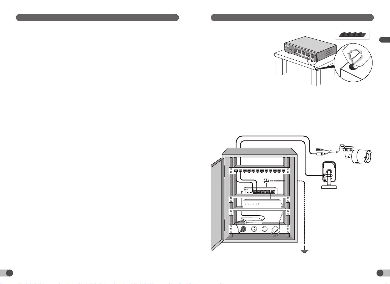
5 - Installation
5.1 Montage sur support
Collez les quatre patins
antidérapants sous le boîtier
du PoE SW4 et posez-le sur
une surface stable.
5.2 Montage en coffret VDI
Vous pouvez installer le PoE SW4 en coffret de communication VDI
(Voix, Données, Image).
- Respectez un espace de 10cm de chaque coté des grilles d’aération.
- Raccordez le boîtier du PoE SW4 à la prise de terre.
LINK/ACT
EXTEND
PWR
PoEMAX
LINK/ACT N/APOESTATUS
POE UPLINK
12 3 4 5
OFF ON
ADSL
4x
4 - Préconisation d’installation
4.1 Pour assurer un fonctionnement optimal
4.2 Type de câble à utiliser
Choisissez le type de câble approprié, en fonction de la distance entre l’équipement à
connecter et le PoE SW4.
- Jusqu’à 200 mètres : Utilisez un câble Ethernet de catégorie 5.
- De 200 à 250 mètres : Utilisez un câble Ethernet de catégorie 6.
• Installez le PoE SW4 en intérieur dans
un environnement sec, bien ventilé et
sans poussière.
• Assurez-vous que l’appareil est
correctement xé à un rack ou posé
sur une surface stable.
• Mettez l’appareil hors tension avant
de connecter ou de déconnecter les
périphériques raccordés.
• Précautions antistatiques:
La poussière peut entraîner
une adsorption électrostatique.
Pour protéger l’appareil contre
les dommages liés à l’électricité
statique, gardez l’environnement de
l’appareil propre, sec et bien ventilé
(Un dépoussiérage régulier est
nécessaire).
• Débranchez l’alimentation électrique
de l’appareil lorsque vous effectuez le
nettoyage.
• Utilisez l’adaptateur d’alimentation
inclus pour alimenter l’appareil.
Assurez-vous que la tension d’entrée
correspond à la valeur indiquée sur
l’étiquette de l’appareil.
• Branchez l’alimentation de l’appareil
après avoir raccordé toutes les autres
connexions.
• N’ouvrez pas le boîtier de l’appareil.
• Placez l’appareil à l’écart du courant
fort.
• Assurez-vous que l’appareil est
correctement mis à la terre.
• N’obstruez pas les grilles d’aération,
conservez un espace libre de 10 cm de
chaque coté de l’appareil.
• Ne placez aucun objet lourd ou de
grande taille sur l’appareil.
• Pour le matériel raccordé par prise
de courant, le socle de prise de
courant doit être installé à proximité
du matériel et doit être aisément
accessible.

9
8
FR
5.3 Raccordement
1- Connectez le port 5 (UPLINK) à votre Box ADSL à l’aide d’un câble Ethernet RJ45.
2- Connectez votre caméra au port 1 (port PoE prioritaire) avec un câble Ethernet de
catégorie 5 ou supérieur.
Si besoin, vous pouvez connecter tout autre périphérique compatible (Caméra,
Téléphone IP, Point d’accès sans l, etc...) sur les ports 2, 3 et 4.
3- Connectez l’adaptateur d’alimentation 230V fourni.
5.4 Mode étendu
Remarque
Pour garantir la performance du mode étendu, utilisez un câble Ethernet de
catégorie 6.
LINK/ACT
EXTEND
PWR
PoE MAX
LINK/ACT N/APOE STATUS
POE UPLINK
12 3 4 5
OFF ON
RJ45
RJ45
RJ45
1
2
3
LINK/ACT
EXTEND
PWR
PoE MAX
LINK/ACT N/APOE STATUS
POE UPLINK
12 3 4 5
OFF ON OFF Ports 1-4: 100 mètres / 100 MB
ON Ports 1-4: de 100 mètres à 250 mètres / 10MB

1110
EN
Technical characteristics
Interfaces 10/100 Mbps RJ45 port 5
Priority port Port 1
Energy Store and transfer Supported
MAC table 1 k
MAC learning Automatic identication
Switching capacity 1 Gbps
PoE power PoE standard IEEE 802.3af, IEEE 802.3at
PoE power supply mode Supports the 8-pin power supply, pins
1,2,3,6 and pins 4,5,7,8 can be supplied
simultaneously
PoE port 1 - 2 - 3 - 4
Max. port output 30 W
Max. total output 58 W
Extended mode Supported
Lightning
protection
classication
Port 4KV
Lightning-protected
power supply
4KV
Electric power INPUT: 100-240 VAC 50/60 Hz 1.5 A
OUTPUT: 51 V DC, 1.25 A
Operating
temperature
0°C/40°C
Humidity: 10% ~ 90%
without condensation
Storage
temperature
-40/70°C
Humidity: 5% ~ 90%
without condensation
Max.
transmission
speed
Ethernet: 10 Mbps (Half Duplex)/20 Mbps
(Full Duplex) Fast Ethernet: 100 Mbps (Half
Duplex)/200 Mbps (Full Duplex)
Network IEEE 802.3, IEEE 802.3u, IEEE 802.3af,
IEEE802.3at, IEEE 802.3x
1 - Presentation 12
2 - Package contents 12
3 - Description 13
3.1 Front panel: 13
3.2 Rear panel 13
4 - Installation recommendations 14
4.1 To achieve optimum operation: 14
4.2 Cable type to use 14
5 - Installation 15
5.1 Mounting on support 15
5.2 Mounting in VDI unit 15
5.3 Connection 16
5.4 Extended mode 16
Because of changes in standards and equipment, the characteristics given in the text
and the illustrations in this document are not binding unless conrmed.

1312
EN
1 - Presentation
The PoE SW4 can supply power, via the Ethernet RJ45 link, to the TYCAM 1100
INDOOR and TYCAM 2100 OUTDOOR cameras or any PoE (Power over Ethernet)
device (4 max.) compatible with standards PoE 802.3af and PoE 802.3at.
The power supply and data can transit simultaneously by ports 1, 2, 3 and 4.
The maximum power: for all 4 outputs is 58 W.
The PoE SW4 supports the Extend mode. The data transmission distance can reach
250 metres with the extended mode and a category 6 Ethernet cable.
This is a plug & play device and requires no special conguration.
2 - Package contents
1
2
3
4
EU
UK
1- PoE SW4
2- 230 V power supply adaptors.
3- Screws and plugs
4- Anti-slip pads
3 - Description
LINK/ACT
EXTEND
PWR
PoE MAX
LINK/ACT N/APOE STATUS
POE UPLINK
12 3 4 5
OFF ON
1 3 4
5
3
2 7 6
3.1 Front panel:
LED Status Description
1 - PWR
On steady The device is properly connected to the mains power.
Off The device is poorly connected or not connected to the
mains power.
2- PoE-MAX On steady The PoE power reaches its lower limit value (6 W).
Flashing The PoE power reaches its maximum (58 W).
Off The PoE power supply operates correctly and the PoE
power available is greater than 6 W.
3- LINK-ACT On steady The corresponding port is correctly connected.
Flashing Transmission or reception of data on the port
Off The corresponding port is not properly connected or is not
connected.
4- PoE status On steady The corresponding port is connected and correctly supplies
power to the PoE peripheral device.
Flashing The PoE output of the corresponding port exceeds 30 W.
Off No POE compatible peripheral is connected.
5 - PoE ports - 1, 2, 3, 4.
6- Port 5 (UPLINK) Box ADSL
7- Extended mode selector. Refer to § 6.4.
3.2 Rear panel
8- Earth connection:
Connection of the PoE SW4 unit to the earth
connection.
9- Power outlet:
Use the 230 V power supply adapter supplied.
51V
8 9
1514
EN
4 - Installation recommendations
4.1 To achieve optimum operation:
4.2 Cable type to use
Choose the appropriate cable according to the distance between the equipment to
connect and the PoE SW4.
- Up to 200 metres: Use a category 5 Ethernet cable.
- From 200 to 250 metres: Use a category 6 Ethernet cable.
• Install the PoE SW4 indoors in
a dry, well-ventilated, dust-free
environment.
• Ensure that the device is correctly
tted to a rack or placed on a stable
surface.
• Switch off the device before
connecting or disconnecting the
connected peripheral devices.
• Antistatic precautions:
Dust can lead to electrostatic
adsorption. To protect the device
against damage from static electricity,
keep the environment of the device
clean, dry and well ventilated (regular
dusting is required).
• Disconnect the mains supply from the
device when you are performing the
cleaning operations.
• Use the power supply adaptor
included to supply power to the
device.
Ensure that the input voltage matches
the value stated on the device label.
• Connect the device power
supply after making all the other
connections.
• Do not open the device unit.
• Place the device away from strong
currents.
• Ensure that the device is correctly
earthed.
• Do not obstruct the ventilation slots,
maintain a free space of 10 cm on
each side of the device.
• Do not place any heavy or large object
on the device.
• For equipment connected to the
power grid, the socket outlet must be
installed close to the equipment and
readily accessible.
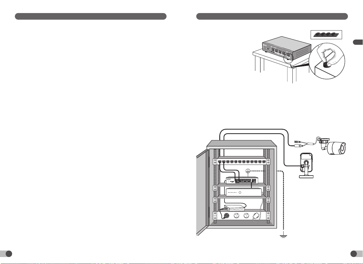
5 - Installation
5.1 Mounting on support
Afx the four anti-slip pads
under the unit of the PoE SW4
and place it on a stable surface.
5.2 Mounting in VDI unit
You can install the PoE SW4 in a VDI communication unit
(Voice, Data, Image).
- Respect a distance of 10 cm on each side of the ventilation slots.
- Connect the PoE SW4 unit to the earth connection.
LINK/ACT
EXTEND
PWR
PoEMAX
LINK/ACT N/APOESTATUS
POE UPLINK
12 3 4 5
OFF ON
ADSL
4x

1716
EN
5.3 Connection
1- Connect port 5 (UPLINK) to your ADSL Box using an Ethernet RJ45 cable.
2- Connect your camera to port 1 (PoE port has priority) with a category 5 or above
Ethernet cable.
If necessary, you can connect any other compatible peripheral device (camera, IP
phone, wireless access point, etc.) to ports 2, 3 and 4.
3- Connect the 230 V power supply adapter supplied.
5.4 Extended mode
Note
To ensure the performance of the extended mode, use a Category 6 Ethernet cable.
LINK/ACT
EXTEND
PWR
PoE MAX
LINK/ACT N/APOE STATUS
POE UPLINK
12 3 4 5
OFF ON
RJ45
RJ45
RJ45
1
2
3
LINK/ACT
EXTEND
PWR
PoE MAX
LINK/ACT N/APOE STATUS
POE UPLINK
12 3 4 5
OFF ON
OFF Ports 1-4: 100 metres/100 MB
ON
Ports 1-4: from 100 metres to 250 metres/10 MB

1918
DE
Technische Daten
Schnittstellen RJ45-Anschluss
10/100 Mbps
5
Prioritärer Port Port 1
Leistung Speichern und
übertragen
Unterstützt
MAC-Tabelle 1 k
MAC-Einlernen Automatisches Einlernen
Schaltkapazität 1 Gbit/s
PoE-Leistung Standard-PoE IEEE 802.3af, IEEE 802.3at
PoE-Stromversorgung Unterstützt die 8-polige
Stromversorgung, die Pins 1, 2, 3 und 6
sowie 4, 5, 7 und 8 können gleichzeitig
versorgt werden.
PoE-Port 1 - 2 - 3 - 4
Max. Port-
Ausgangsleistung
30 W
Max. Gesamt-
Ausgangsleistung
58 W
Erweiterter Modus Unterstützt
Blitzschutzklasse Port 4 KV
Blitzschutz-Netzteil 4 KV
Stromversorgung INPUT: 100-240 VAC; 50/60 Hz; 1,5 A
OUTPUT: 51 VDC; 1,25 A
Betriebstemperatur 0 °C / 40 °C
Luftfeuchtigkeit: 10 % ~ 90 %
ohne Kondensation
Lagertemperatur -40 / 70 °C
Luftfeuchtigkeit: 5% ~ 90 %
ohne Kondensation
Max. Bitrate Ethernet: 10 Mbit/s (Half Duplex) /
20 Mbit/s (Full Duplex) Fast Ethernet:
100 Mbit/s (Half Duplex) / 200 Mbit/s
(Full Duplex)
Netzwerk IEEE 802.3, IEEE 802.3u, IEEE
802.3af, IEEE802.3at, IEEE 802.3x
1 - Präsentation 20
2 - Packungsinhalt 20
3 - Beschreibung 21
3.1 Vorderseite: 21
3.2 Rückseite 21
4 - Installationshinweis 22
4.1 Für den optimalen Betrieb: 22
4.2 Zu verwendende Kabel 22
5 - Installation 23
5.1 Montage auf einer Halterung 23
5.2 Montage im VDI-Gehäuse 23
5.3 Anschluss 24
5.4 Erweiterter Modus 24
Aufgrund möglicher Weiterentwicklungen von Normen und Produkten sind die in der
vorliegenden Anleitung aufgeführten Angaben und Bilder nur bei entsprechender
Bestätigung von uns verbindlich.

2120
DE
1 - Präsentation
Der PoE SW4 versorgt die Kameras TYCAM 1100 INDOOR und TYCAM 2100
OUTDOOR bzw. alle mit der PoE-Technologie (Power over Ethernet) kompatiblen
Geräte (max. 4), gemäß den Standards PoE 802.3af und PoE 802.3at.
Der Strom- und Datenuss geschieht gleichzeitig über die Ports 1, 2, 3 und 4.
Die maximale Leistung für alle 4 Ausgänge beträgt 58 W.
Der PoE SW4 unterstützt den erweiterten Modus. Der erweiterte Modus und
das Ethernetkabel der Kategorie 6 ermöglichen eine maximale Entfernung der
Datenübertragung von 250 m abzudecken.
Dieses Plug-and-Play-Gerät erfordert keine besondere Konguration.
2 - Packungsinhalt
1
2
3
4
EU
UK
1 - PoE SW4
2 - 230V-Netzteil.
3 - Schrauben und Dübel
4 - Rutschfeste Pads.
3 - Beschreibung
LINK/ACT
EXTEND
PWR
PoE MAX
LINK/ACT N/APOE STATUS
POE UPLINK
12 3 4 5
OFF ON
1 3 4
5
3
2 7 6
3.1 Vorderseite:
Kontrollleuchte Status Beschreibung
1 - PWR
Leuchtet
durchgehend
Das Gerät wurde ordnungsgemäß mit der
Stromversorgung verbunden.
Aus Das Gerät wurde nicht richtig verbunden oder wird
nicht mit Strom versorgt.
2 - PoE-MAX Leuchtet
durchgehend
Die PoE-Leistung erreicht ihren unteren Grenzwert
(6 W).
Blinkt Die PoE-Leistung erreicht ihren oberen Grenzwert
(58 W).
Aus
Die PoE-Stromversorgung funktioniert ordnungsgemäß
und
die verfügbare PoE-Leistung liegt über 6 W.
3 - LINK-ACT Leuchtet
durchgehend
Der entsprechende Port wurde ordnungsgemäß
angeschlossen.
Blinkt Versand bzw. Empfang von Daten über den Port.
Aus Der entsprechende Port wurde nicht richtig oder
überhaupt nicht angeschlossen.
4 - PoE-Status Leuchtet
durchgehend
Der entsprechende Port ist angeschlossen und wird
über das PoE-Gerät mit Strom versorgt.
Blinkt Die PoE-Ausgangsleistung des Ports überschreitet
30 W.
Aus Es wurde kein kompatibles PoE-Gerät verbunden.
5 - PoE-Ports - 1, 2, 3, 4.
6 - Port 5 (UPLINK) ADSL-Router
7 - Auswahl des erweiterten Modus. Siehe Abschnitt 6.4.
3.2 Rückseite
8 - Erdung:
Verbindung des PoE-Gehäuses SW4 mit der Erdung.
9 - Netzanschluss:
Verwenden Sie das mitgelieferte 230V-Netzteil.
51V
8 9
2322
DE
4 - Installationshinweis
4.1 Für den optimalen Betrieb:
4.2 Zu verwendende Kabel
Wählen Sie das geeignete Kabel, je nach Entfernung zwischen dem zu verbindenden
Gerät und dem PoE SW4.
- Bis zu 200 m: Verwenden Sie ein Ethernetkabel der Kategorie 5.
- Von 200 bis 250 m: Verwenden Sie ein Ethernetkabel der Kategorie 6.
• Installieren Sie den PoE SW4 in
einem trockenen, gut belüfteten und
staubfreien Innenraum.
• Vergewissern Sie sich, dass das Gerät
richtig mit an einem Rack befestigt
ist oder auf einer stabilen Oberäche
steht.
• Schalten Sie das Gerät aus, bevor Sie
die verbundenen Peripheriegeräte
verbinden oder trennen.
• Antistatische Vorsichtsmaßnahmen:
Staub kann zur elektrostatischen
Adsorption führen. Die Umgebung
des Gerätes muss sauber und trocken
gehalten und gut belüftet werden
(Staub ist regelmäßig zu entfernen),
um das Gerät vor Schäden durch
statische Elektrizität zu schützen.
• Unterbrechen Sie die
Spannungsversorgung des Gerätes
vor der Reinigung.
• Verwenden Sie das im Lieferumfang
des Gerätes enthaltene Netzteil.
Stellen Sie sicher, dass die
Eingangsspannung mit dem auf dem
Typenschild des Gerätes angegebenen
Wert übereinstimmt.
• Stellen Sie die Spannungsversorgung
her, nachdem alle anderen
Verbindungen hergestellt worden sind.
• Öffnen Sie nicht das Gerätegehäuse.
• Halten Sie das Gerät von starken
Stromquellen fern.
• Stellen Sie sicher, dass das Gerät
ordnungsgemäß geerdet wurde.
• Blockieren Sie nicht die
Lüftungsschlitze und halten Sie einen
Abstand von 10 cm auf beiden Seiten
des Gerätes ein.
• Stellen Sie keine schweren oder
großen Gegenstände auf dem
Gerät ab.
• Bei Geräten mit Steckdosen-anschluss
muss die Steckdose in der Nähe
des Gerätes eingebaut und leicht
zugänglich sein.
5 - Installation
5.1 Montage auf einer Halterung
Kleben Sie die vier rutschfesten
Pads unter das Gehäuse des
PoE SW4 und stellen Sie es auf
eine stabile Oberäche.
5.2 Montage im VDI-Gehäuse
Sie können den PoE SW4 in einer VDI-Kommunikationsbox installieren
(Sprache, Daten, Bilder).
- Beachten Sie einen Abstand von 10 cm auf jeder Seite der Lüftungsschlitze.
- Verbinden Sie das Gehäuse des PoE SW4 mit der Erdung.
LINK/ACT
EXTEND
PWR
PoEMAX
LINK/ACT N/APOESTATUS
POE UPLINK
12 3 4 5
OFF ON
ADSL
4x

2524
DE
5.3 Anschluss
1 - Verbinden Sie den Port 5 (UPLINK) über ein Ethernetkabel (RJ45) mit Ihrem
ADSL-Router.
2 - Verbinden Sie Ihre Kamera mit dem Port 1 (prioritärer PoE-Port) mit einem
Ethernetkabel der Kategorie 5 oder höher.
Bei Bedarf können Sie ein beliebiges kompatibles Gerät (Kamera, IP-Telefon,
Wireless Access Point ...) an die Ports 2, 3 und 4 anschließen.
3 - Verbinden Sie das mitgelieferte 230V-Netzteil.
5.4 Erweiterter Modus
Hinweis
Verwenden Sie ein Ethernetkabel der Kategorie 6, um die Leistung im erweiterten
Modus zu gewährleisten.
LINK/ACT
EXTEND
PWR
PoE MAX
LINK/ACT N/APOE STATUS
POE UPLINK
12 3 4 5
OFF ON
RJ45
RJ45
RJ45
1
2
3
LINK/ACT
EXTEND
PWR
PoE MAX
LINK/ACT N/APOE STATUS
POE UPLINK
12 3 4 5
OFF ON OFF Ports 1-4: 100 m/100 MB
ON Ports 1-4: von 100 m bis 250 m/10 MB

2726
IT
Caratteristiche tecniche
Interfacce Porta RJ45 10/100
Mbps
5
Porta prioritaria Porta 1
Prestazioni Salvare e trasferire Supportato
Table MAC 1 k
Apprendimento MAC Auto-apprendimento
Capacità di
commutazione
1 Gbps
Potenza PoE PoE standard IEEE 802.3af, IEEE 802.3at
Modalità di
alimentazione PoE
Supporta l’alimentazione 8 pin, i pin 1,2,3,6
e i pin 4,5,7,8 possono essere alimentati
simultaneamente
Porta PoE 1 - 2 - 3 - 4
Uscita porta Max. 30W
Uscita totale Max. 58W
Modalità estesa Supportato
Classicazione
contro i fulmini
Porta 4KV
Alimentazione protetta
contro i fulmini
4KV
Alimentazione
elettrica
INPUT: 100-240VAC 50/60Hz 1,5A
OUTPUT: 51V DC, 1.25A
Temperatura di
funzionamento
0 °C / 40 °C
Umidità: 10% ~ 90%
senza condensazione
Temperatura di
stoccaggio
-40 / 70 °C
Umidità: 5% ~ 90%
senza condensazione
Velocità di
trasmissione max.
Ethernet: 10Mbps (Half Duplex) / 20Mbps
(Full Duplex) Fast Ethernet: 100Mbps (Half
Duplex) / 200Mbps (Full Duplex)
Rete IEEE 802.3, IEEE 802.3u, IEEE 802.3af,
IEEE802.3at, IEEE 802.3x
1 - Presentazione 28
2 - Contenuto della confezione 28
3 - Descrizione 29
3.1 Lato anteriore: 29
3.2 Lato posteriore 29
4 - Consigli di installazione 30
4.1 Per assicurare un funzionamento ottimale 30
4.2 Tipo di cavo da utilizzare 30
5 - Installazione 31
5.1 Montaggio su supporto 31
5.2 Montaggio in scatola VDI 31
5.3 Collegamento 32
5.4 Modalità estesa 32
A causa dell’evoluzione costante delle normative e del materiale, le caratteristiche
indicate nel testo e le immagini contenute nel presente documento sono da ritenersi
vincolanti solo dopo una conferma da parte dei nostri servizi.

2928
IT
1 - Presentazione
Il PoE SW4 permette di alimentare, attraverso il collegamento Ethernet RJ45, le
telecamere TYCAM 1100 INDOOR e TYCAM 2100 OUTDOOR o ogni apparecchio (4
max.) compatibile PoE (Power over Ethernet) alle norme PoE 802.3af e PoE 802.3at.
L’alimentazione e i dati possono transitare simultaneamente attraverso le porte 1, 2,
3 e 4.
La potenza massima per l’insieme delle 4 uscite è di 58W .
Il PoE SW4 supporta la modalità Extend. Con la modalità estesa e un cavo Ethernet di
categoria 6, la distanza di trasmissione dei dati può raggiungere 250 metri.
Questo apparecchio è di tipo “plug & play”, non necessita di alcuna congurazione
particolare.
2 - Contenuto della confezione
1
2
3
4
EU
UK
1- PoE SW4
2- Adattatori di alimentazione 230V.
3- Viti e tasselli
4- Pattini antiscivolo
3 - Descrizione
LINK/ACT
EXTEND
PWR
PoE MAX
LINK/ACT N/APOE STATUS
POE UPLINK
12 3 4 5
OFF ON
1 3 4
5
3
2 7 6
3.1 Lato anteriore:
Spia Stato Descrizione
1 - PWR
Accesa ssa L’apparecchio è collegato correttamente all’alimentazione
elettrica.
Spenta L’apparecchio è collegato in modo scorretto, oppure non è
collegato all’alimentazione elettrica.
2- PoE-MAX Accesa ssa La potenza PoE raggiunge il suo valore limite inferiore
(6W).
Lampeggiante La potenza PoE raggiunge il suo valore limite massimo
(58 W).
Spenta L’alimentazione PoE funziona correttamente e la potenza
PoE disponibile è superiore a 6W.
3- LINK-ACT Accesa ssa La porta corrispondente è collegata correttamente.
Lampeggiante Trasmissione o ricezione dei dati sulla porta
Spenta La porta corrispondente non è collegata correttamente,
oppure non è collegata.
4- PoE status Accesa ssa La porta corrispondente è collegata e alimenta
correttamente la periferica PoE.
Lampeggiante L’uscita PoE della porta corrispondente supera 30W.
Spenta Nessuna periferica compatibile POE è collegata.
5 - Porte PoE - 1, 2, 3, 4.
6- Porta 5 (UPLINK) Modem ADSL
7- Selettore modalità estesa. Consultate il § 6.4.
3.2 Lato posteriore
8- Presa di terra:
Collegamento della scatola PoE SW4 alla presa di
terra.
9- Presa di alimentazione:
Utilizzate l’adattatore di alimentazione 230V
fornito.
51V
8 9

3130
IT
4 - Consigli di installazione
4.1 Per assicurare un funzionamento ottimale
4.2 Tipo di cavo da utilizzare
Scegliete il tipo di cavo adatto, in base alla distanza tra il dispositivo da collegare e il
PoE SW4.
- Fino a 200 metri: Utilizzate un cavo Ethernet di categoria 5.
- Da 200 a 250 metri: Utilizzate un cavo Ethernet di categoria 6.
• Installate il PoE SW4 all’interno in un
ambiente asciutto, ben ventilato e
privo di polvere.
• Assicuratevi che l’apparecchio sia
ssato correttamente a un rack o
appoggiato su una supercie stabile.
• Mettete l’apparecchio fuori tensione
prima di collegare o di scollegare le
periferiche collegate.
• Precauzioni antistatiche:
La polvere può causare un
assorbimento elettrostatico.
Per proteggere l’apparecchio
contro i danni legati all’elettricità
statica, mantenete l’ambiente
dell’apparecchio pulito, asciutto e
ben ventilato (Una depolverazione
regolare è necessaria).
• Scollegate l’alimentazione elettrica
dell’apparecchio mentre effettuate
la pulizia.
• Utilizzate l’adattatore di
alimentazione incluso per alimentare
l’apparecchio.
Assicuratevi che la tensione
di ingresso corrisponda al
valore indicato sull’etichetta
dell’apparecchio.
• Collegate l’alimentazione
dell’apparecchio dopo avere collegato
tutti gli altri collegamenti.
• Non aprite la scatola dell’apparecchio.
• Posizionate l’apparecchio lontano da
correnti forti.
• Assicuratevi che l’apparecchio sia
correttamente messo a terra.
• Non ostruite le griglie di aerazione,
mantenete uno spazio libero di 10 cm
su ogni lato dell’apparecchio.
• Non collocate alcun oggetto pesante o
di grandi dimensioni sull’apparecchio.
• Per il materiale collegato tramite
presa di corrente la presa ssa deve
essere installata vicino al materiale e
deve essere facilmente raggiungibile.
5 - Installazione
5.1 Montaggio su supporto
Incollate i quattro pattini
antiscivolo sotto la scatola del
PoE SW4 e appoggiatelo su una
supercie stabile.
5.2 Montaggio in scatola VDI
Potete installare il PoE SW4 nella scatola di comunicazione VDI
(Voce, Dati, Immagine).
- Mantenete uno spazio di 10 cm su ogni lato delle griglie di aerazione.
- Collegate la scatola del PoE SW4 alla presa di terra.
LINK/ACT
EXTEND
PWR
PoEMAX
LINK/ACT N/APOESTATUS
POE UPLINK
12 3 4 5
OFF ON
ADSL
4x

3332
IT
5.3 Collegamento
1- Collegate la porta 5 (UPLINK) al vostro modem ADSL usando un cavo Ethernet
RJ45.
2- Collegate la vostra telecamera alla porta 1 (porta PoE prioritaria) con un cavo
Ethernet di categoria 5 o superiore.
Se necessario, potete collegare ogni altra periferica compatibile (Telecamera,
Telefono IP, Punto di accesso senza lo, ecc.)
sulle porte 2, 3 e 4.
3- Collegate l'adattatore di alimentazione 230V fornito.
5.4 Modalità estesa
Nota
Per garantire le prestazioni della modalità estesa, utilizzate un cavo Ethernet di
categoria 6.
LINK/ACT
EXTEND
PWR
PoE MAX
LINK/ACT N/APOE STATUS
POE UPLINK
12 3 4 5
OFF ON
RJ45
RJ45
RJ45
1
2
3
LINK/ACT
EXTEND
PWR
PoE MAX
LINK/ACT N/APOE STATUS
POE UPLINK
12 3 4 5
OFF ON
OFF Porte 1-4: 100 metri / 100 MB
ON Porte 1-4: da 100 metri a 250 metri / 10 MB

3534
ES
Características técnicas
Interfaces Puerto RJ45 10/100
Mbps
5
Puerto prioritario Puerto 1
Rendimiento Almacenar y transferir Compatible
Tabla MAC 1 k
Aprendizaje MAC Auto-aprendizaje
Capacidad de
conmutación
1 Gbps
Potencia PoE PoE estándar IEEE 802.3af, IEEE 802.3at
Modo de alimentación
PoE
Admite la alimentación de 8 terminales; los
terminales 1, 2, 3, 6 y los terminales 4, 5, 7, 8
se pueden alimentar de forma simultánea
Puerto PoE 1 - 2 - 3 - 4
Salida de puerto máx. 30 W
Salida total máx. 58 W
Modo extendido Compatible
Clasicación
contra los rayos
Puerto 4 KV
Alimentación protegida
contra los rayos
4 KV
Alimentación
eléctrica
ENTRADA: 100-240 VCA 50/60 Hz 1,5 A
SALIDA: 51 VCC, 1,25 A
Temperatura de
funcionamiento
0°C / 40°C
Humedad: 10% ~ 90%
sin condensación
Temperatura de
almacenamiento
-40 / 70°C
Humedad: 5% ~ 90%
sin condensación
Velocidad de
transmisión
máxima
Ethernet: 10 Mbps (Half Duplex) / 20 Mbps
(Full Duplex) Fast Ethernet: 100 Mbps (Half
Duplex) / 200 Mbps (Full Duplex)
Red IEEE 802.3, IEEE 802.3u, IEEE 802.3af,
IEEE802.3at, IEEE 802.3x
1 - Presentación 36
2 - Contenido del paquete 36
3 - Descripción 37
3.1 Parte frontal: 37
3.2 Parte trasera 37
4 - Recomendaciones de instalación 38
4.1 Para garantizar un funcionamiento óptimo: 38
4.2 Tipo de cable a utilizar 38
5 - Instalación 39
5.1 Montaje en soporte 39
5.2 Montaje en caja VDI 39
5.3 Conexión 40
5.4 Modo extendido 40
Debido a la evolución de las normas y del material, las características indicadas en el
texto y las imágenes de este documento sólo nos comprometen después de haber sido
conrmados por nuestros servicios.

3736
ES
1 - Presentación
El módulo PoE SW4 permite alimentar, a través del enlace Ethernet RJ45, las cámaras
TYCAM 1100 INTERIOR y TYCAM 2100 EXTERIOR o cualquier dispositivo (4 como
máx.) compatible con PoE (Power over Ethernet, Alimentación a través de Ethernet)
bajo las normas PoE 802.3af y PoE 802.3at.
La alimentación y los datos pueden transitar de manera simultánea por los puertos 1,
2, 3 y 4.
La potencia máxima para las 4 salidas es de 58 W.
El módulo PoE SW4 admite el modo Extendido. Con el modo extendido y un cable
Ethernet de categoría 6, la distancia de transmisión de datos puede llegar a 250
metros.
Este dispositivo es «plug & play», no necesita ninguna conguración particular.
2 - Contenido del paquete
1
2
3
4
EU
UK
1 - PoE SW4
2 - Adaptadores de alimentación de 230 V
3 - Tornillos y tacos
4 - Patines antideslizantes
3 - Descripción
LINK/ACT
EXTEND
PWR
PoE MAX
LINK/ACT N/APOE STATUS
POE UPLINK
12 3 4 5
OFF ON
1 3 4
5
3
2 7 6
3.1 Parte frontal:
Testigo Estado Descripción
1 - PWR
Encendido jo El aparato está conectado correctamente a la
alimentación eléctrica.
Apagado El aparato está mal conectado o no está conectado a la
alimentación eléctrica.
2 - PoE-MAX Encendido jo La potencia PoE alcanza su valor límite inferior (6 W).
Intermitente La potencia PoE alcanza su máximo (58 W).
Apagado La alimentación PoE funciona correctamente y la
potencia PoE disponible es mayor de 6 W.
3 - LINK-ACT Encendido jo El puerto correspondiente está conectado
correctamente.
Intermitente Transmisión o recepción de datos a través del puerto
Apagado El puerto correspondiente no está conectado
correctamente o no lo está.
4- Estado PoE Encendido jo El puerto correspondiente está conectado y alimenta
correctamente al periférico PoE.
Intermitente La salida PoE del puerto correspondiente sobrepasa los
30 W.
Apagado No hay conectado ningún periférico PoE compatible.
5 - Puertos PoE - 1, 2, 3, 4.
6 - Puerto 5 (UPLINK) Pasarela ADSL
7 - Selector de modo extendido. Consulte el apdo. 6.4.
3.2 Parte trasera
8 - Toma de tierra:
Conexión del módulo PoE SW4 a la toma de tierra.
9 - Toma de alimentación:
Use el adaptador de alimentación de 230 V
suministrado.
51V
8 9

3938
ES
4 - Recomendaciones de instalación
4.1 Para garantizar un funcionamiento óptimo:
4.2 Tipo de cable a utilizar
Elija el tipo de cable adecuado en función de la distancia entre el equipo que va a
conectarse y el PoE SW4.
- Hasta 200 metros: Use un cable Ethernet de categoría 5.
- De 200 a 250 metros: Use un cable Ethernet de categoría 6.
• Instale el módulo PoE SW4 en el
interior en un entorno seco, bien
ventilado y sin polvo.
• Asegúrese de que el aparato esté
correctamente jado a un bastidor o
ubicado sobre una supercie estable.
• Apague el aparato antes de conectar
o desconectar los periféricos
conectados.
• Precauciones antiestáticas:
El polvo puede causar adsorción
electrostática. Para proteger el
aparato contra los daños relacionados
con la electricidad estática, mantenga
el entorno del aparato limpio, seco
y bien ventilado (hay que eliminar el
polvo con regularidad).
• Desconecte la alimentación eléctrica
del aparato cuando realice la limpieza.
• Utilice el adaptador de alimentación
incluido para alimentar el aparato.
Asegúrese de que la tensión de
entrada coincida con el valor indicado
en la etiqueta del aparato.
• Conecte la alimentación del aparato
una vez realizadas todas las demás
conexiones.
• No abra la caja del aparato.
• Coloque el aparato lejos de corrientes
fuertes.
• Asegúrese de que el aparato está
conectado a tierra correctamente.
• No obstruya las rejillas de aireación,
mantenga un espacio libre 10 cm a
cada lado del aparato.
• No coloque objetos pesados o grandes
sobre el aparato.
• Para el material conectado por toma
de corriente, el enchufe debe estar
instalado cerca del material y debe ser
fácilmente accesible.
5 - Instalación
5.1 Montaje en soporte
Pegue los cuatro patines
antideslizantes debajo de la
caja del módulo PoE SW4 y
colóquela sobre una supercie
estable.
5.2 Montaje en caja VDI
Puede instalar el módulo PoE SW4 en una caja de comunicación VDI (Voz, Datos,
Imagen).
- Respete un espacio de 10 cm a cada lado de las rejillas de aireación.
- Conecte la caja del módulo PoE SW4 a la toma de tierra.
LINK/ACT
EXTEND
PWR
PoEMAX
LINK/ACT N/APOESTATUS
POE UPLINK
12 3 4 5
OFF ON
ADSL
4x
Other manuals for PoE SW4
1
This manual suits for next models
1
Table of contents
Languages:
Other DELTA DORE Switch manuals

DELTA DORE
DELTA DORE TYXIA 4600 User manual

DELTA DORE
DELTA DORE TYXIA 2310 User manual

DELTA DORE
DELTA DORE TYDOM 1.0 User manual

DELTA DORE
DELTA DORE Tydom Pro User manual

DELTA DORE
DELTA DORE TYDOM 1.0 User manual

DELTA DORE
DELTA DORE Tydom Home User manual

DELTA DORE
DELTA DORE Tyxia 2310 User manual

DELTA DORE
DELTA DORE 3513140002980 User manual

DELTA DORE
DELTA DORE TYXIA 4801 User manual

DELTA DORE
DELTA DORE TYXIA 4840 User manual


