delta-mobrey 2468CA User manual
Operating Manual
24685033, Rev BA
Jan 2022
Delta Mobrey Hydrastep 2468CA and 2468CC
Electronic Gauging System (Single Input Board)


Operating Manual
24685033, Rev BA
Title Page
Jan 2022
Hydrastep 2468CA and 2468CC
i
Mobrey™Hydrastep 2468CA and 2468CC
Read this manual before working with the product. For personal and system safety, and optimum
product performance, make sure you thoroughly understand the contents before installing, using, or
maintaining this product.
Failure to follow these guidelines could result in death or severe injury.
Avoid contact with the leads and terminals. High voltage that may be present on leads can cause
electrical shock.
Explosive atmospheres
Never operate the equipment, or any sensors connected to the equipment, in a potentially explosive
atmosphere. It is not intrinsically safe and could possibly cause an explosion.
Grounding
To minimise the risk of electrical shocks, connect equipment to a protective ground (earth) at all times.
Grounding is essential not just when the power supply, measurement, or control circuits are connected,
but also while equipment is not powered-up.
The Hydrastep Controller Unit must be connected to ground (earth) using the marked case stud before
control or signal leads are connected. The ground (earth) connection must have a rating of 25 Amps.
Avoid using unsafe equipment
If in any doubt as to the serviceability of the equipment, do not use it. Get the equipment checked by a
qualified service technician.
The equipment may be unsafe if any of the following statements apply:
▪It shows visible damage.
▪It failed to perform an intended operation.
▪It was subjected to severe physical stress.
▪Storage conditions were unfavourable.
Live electrical wires
When connected to a power supply, the opening of the lid and removal of parts could expose live
electrical wires. Never open the Hydrastep Controller Unit while it is powered-up.
Isolate the equipment from all power and signal sources before opening the hinged lid to make an
adjustment, replace a replacement, perform maintenance, or make repairs. Only authorised, qualified
personnel should perform these tasks.
Equipment modification
To avoid introducing safety hazards, never install non-standard parts in the equipment or make any
unauthorised modification. Return the equipment to Delta Mobrey Limited for service and repair.
Warning

Title Page
Jan 2022
Operating Manual
24685033, Rev BA
ii
Hydrastep 2468CA and 2468CC
Cleaning
To clean the instrument, use a damp cloth with a mild, water-based cleaner. Clean the exterior of the
equipment only. Do not allow liquids to enter or spill onto the equipment.
Mains ac power supply
Never operate the equipment from a line voltage or frequency more than specified. Otherwise, the
insulation of internal components may break down and cause excessive leakage currents.
To allow the controller unit to be isolated from the ac supply, route the supply through a switch (or
circuit breaker). The device must be within easy reach of the operator and identified clearly as the
means of supply isolation.
Fuses
Check the fuse (accessible from the interior) is the correct rating before powering the equipment. The
rating of the ac line fuse must be in accordance with the voltage of the ac supply.
Should any fuse continually blow, do not insert a fuse of a higher rating. Switch the equipment off,
clearly label it as “unserviceable” and inform a service technician.
Not designed for nuclear-qualified applications
Hydrastep products are not for nuclear-qualified applications. Using non-nuclear qualified products in
applications that require nuclear-qualified hardware or products may cause inaccurate readings.
For information on nuclear-qualified products, contact Delta Mobrey Limited.
Pressure parts
For installation under the Pressure Equipment Directive (PED) 2014/68/EU, refer to safety
instructionmanual 24688006/SI.
For installation under ATEX directive 2014/34/E, refer to safety instruction manual 24685033/SI.
Caution
Operating Manual
24685033, Rev BA
Title Page
Jan 2022
Hydrastep 2468CA and 2468CC
iii
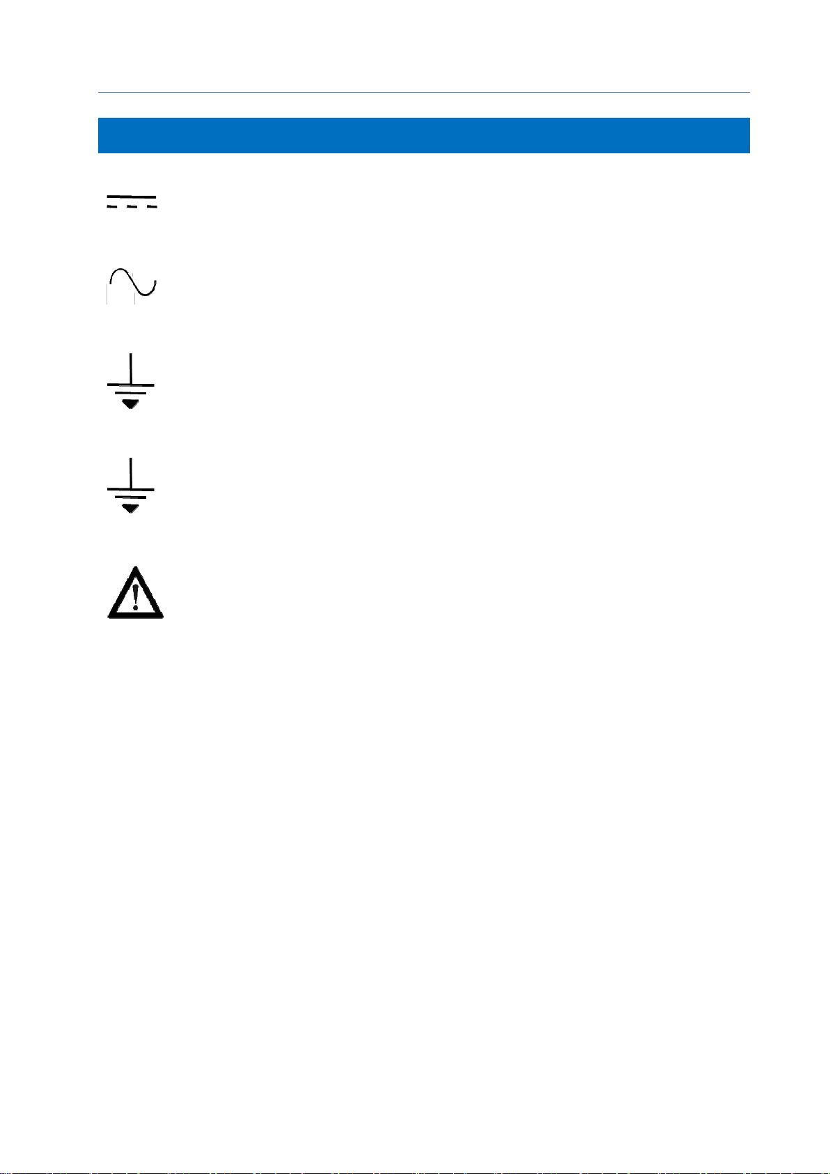
Direct Current
Alternating Current
Earth (ground) terminal
Protective conductor terminal
Caution (refer to accompanying documents)
Symbols used in this manual and on the control unit

Title Page
Jan 2022
Operating Manual
24685033, Rev BA
iv
Hydrastep 2468CA and 2468CC

Operating Manual
24685033, Rev BA
Contents
Jan 2022
Hydrastep 2468CA and 2468CC
v
Contents
Chapter 1 - Introduction
1.1 HYDRASTEP 2468 STEAM AND WATER GAUGING SYSTEM ................................................... 1-1
1.2 HOW IT WORKS............................................................................................................................. 1-2
1.3 ELECTRONICS IN THE CONTROLLER UNIT............................................................................... 1-5
1.3.1 Input board....................................................................................................................... 1-5
1.3.2 Display board................................................................................................................... 1-6
1.3.3 Output boards (optional) .................................................................................................. 1-6
Chapter 2 –Mechanical Installation
2.1 WATER COLUMN AND ELECTRODES INSTALLATION.............................................................. 2-1
2.2 CONTROLLER UNIT INSTALLATION............................................................................................ 2-1
2.3 REMOTE DISPLAY UNIT INSTALLATION..................................................................................... 2-2
Chapter 3 –Electrical Installation
3.1 INPUT BOARD................................................................................................................................ 3-1
3.1.1 Power supply options on the Input board......................................................................... 3-1
3.1.2 Power cables and connections for the Input board (ac mains version) ........................... 3-3
3.1.3 Power cables and connections for the Input board (dc supply version) .......................... 3-4
3.1.4 Electrode cables and connections on the Input board..................................................... 3-5
3.1.5 Input board: Analogue output (optional) ........................................................................ 3-10
3.1.5 Electrode error configuration (standard) on the Input board.......................................... 3-12
3.2 DISPLAY BOARD ......................................................................................................................... 3-15
3.2.1 Configuration options for the Display board................................................................... 3-15
3.2.2 Compatibility setting for new and legacy Input boards .................................................. 3-17
3.2.3 Remote display unit connections................................................................................... 3-17
3.2.4 Opto-isolated fault output connection (optional) ............................................................ 3-17
3.3 OUTPUT OPTION BOARDS......................................................................................................... 3-19
3.2.1 Installing a new Output board........................................................................................ 3-21
3.2.2 Configuration options on an Output board..................................................................... 3-22
3.2.3 Connections to an Output board.................................................................................... 3-26
Chapter 4 –Starting-up The First Time
4.1 HYDRASTEP START-UP ............................................................................................................... 4-1

Contents
Jan 2022
Operating Manual
24685033, Rev BA
vi
Hydrastep 2468CA and 2468CC
Chapter 5 –Troubleshooting
5.1 QUICK TROUBLESHOOTING CHART .......................................................................................... 5-1
5.2 TROUBLESHOOTING THE CONTROLLER UNIT......................................................................... 5-2
5.2.1 Fault analysis and corrective actions............................................................................... 5-2
5.2.2 Replacing Input and Display boards................................................................................ 5-5
5.2.3 Fitting or replacing an optional Output board................................................................... 5-6
5.3 TROUBLESHOOTING THE REMOTE DISPLAYS......................................................................... 5-8
5.3.1 Fault analysis and corrective actions............................................................................... 5-8
5.4 TROUBLESHOOTING THE WATER COLUMNS......................................................................... 5-12
5.4.1 Background.................................................................................................................... 5-12
5.4.2 Safety precautions ......................................................................................................... 5-12
5.4.3 Water column isolation................................................................................................... 5-13
5.4.4 Electrode and electrode seal leaks................................................................................ 5-13
5.4.5 Changing the low-pressure electrodes and gaskets...................................................... 5-15
5.4.6 Changing the high-pressure electrodes and gaskets .................................................... 5-16
5.4 WATER COLUMN COMMISSIONING OR RECOMMISSIONING............................................... 5-16
5.5.1 Venting and draining for valve repairs ........................................................................... 5-17
5.5.2 Water column transient response.................................................................................. 5-17
5.5.3 Clearing water column and pipework blockages ........................................................... 5-18
5.5.4 Water column life ........................................................................................................... 5-18

Operating Manual
24685033, Rev BA
Contents
Jan 2022
Hydrastep 2468CA and 2468CC
vii
Appendix A –Wiring Diagrams
A.1 CONTROLLER UNIT AND ELECTRODES ....................................................................................A-1
Appendix B –Specifications
B.1 HYDRASTEP CONTROLLER UNIT SPECIFICATIONS .................................................................B-1
B.1.1 Core specifications for the controller unit.........................................................................B-1
B.1.2 Specifications for the optional Relay Output board..........................................................B-2
B.1.3 Specifications for the optional Delay-Relay Output board................................................B-2
B.2 REMOTE DISPLAY UNIT SPECIFICATIONS.................................................................................B-3
B.2.1 Core specifications for the controller unit.........................................................................B-3
B.2.3 Cabling specifications for the remote display units..........................................................B-3
B.3 ELECTRODES AND WATER COLUMNS SPECIFICATIONS .......................................................B-4
B.3.1 Core specifications for the electrodes..............................................................................B-4
B.3.2 Core specifications for the water columns .......................................................................B-5
Appendix C –Parts Lists
C.1 HYDRASTEP CONTROLLER UNIT PARTS ..................................................................................C-1
C.1.1 Core parts for the controller unit.......................................................................................C-1
C.1.2 Relay Output option board (PCB 24680504)....................................................................C-1
C.1.3 Delay Relay Output option board (PCB 24680509)............................................................C-1
C.2 ACCESSORIES ...............................................................................................................................C-2
C.2.1 Water column and electrode accessories.........................................................................C-2

Contents
Jan 2022
Operating Manual
24685033, Rev BA
viii
Hydrastep 2468CA and 2468CC
Appendix D –Remote Display Units
D.1 REMOTE DISPLAY OPTIONS........................................................................................................D-1
D.2 RECONFIGURING THE 24683BB AND 24683C DISPLAYS.........................................................D-3
D.3 RECONFIGURING THE 24683D DISPLAY....................................................................................D-4
D.4 INSTALLING THE 24683BB AND 24683C UNITS IN A PANEL....................................................D-5
D.5 INSTALLING THE 24683D WALL MOUNTED UNIT......................................................................D-5
D.6 ELECTRICAL CONNECTIONS.......................................................................................................D-7
D.6.1 One Remote Display Unit powered by the Controller Unit ....................................................D-7
D.6.2 Other Remote Display Units powered by local supplies ...................................................D-8
D.6.3 Loop resistance.................................................................................................................D-10
D.6.4 Connecting cables to the remote display ........................................................................D-10
D.6.5 Connecting the display cables to the controller unit......................................................…D-10
D.7 SYSTEM OPERATION .......................................................................................................................D-11
Appendix E –Hydrastep Water Columns and Electrodes
E.1 WATER COLUMNS ........................................................................................................................E-1
E.1.1 Low-pressure water columns.............................................................................................E-1
E.1.2 High-pressure water columns............................................................................................E-1
E.1.3 Supercritical high-pressure water column.........................................................................E-2
E.2 ELECTRODES..................................................................................................................................E-5
E.2.1 Low-pressure electrodes...................................................................................................E-5
E.2.2 High-pressure electrodes..................................................................................................E-6
E.3 INSTALLATION PROCEDURES ......................................................................................................E-7
E.3.1 Scope of procedures..........................................................................................................E-7
E.3.2 Storage..............................................................................................................................E-7
E.4 INSTALLATION OF THE WATER COLUMN...................................................................................E-8
E.5 INSPECTION OF MECHANICAL INSTALLATION WORK..............................................................E-10
Appendix F -- CSA Certification Drawings
F.1 CSA CONTROL DRAWINGS..........................................................................................................F-1

Operating Manual
24685033, Rev BA
Introduction
Jan 2022
1-1
Hydrastep 2468CA and 2468CC
1
Introduction
1.1
HYDRASTEP 2468 STEAM AND WATER GAUGING SYSTEM
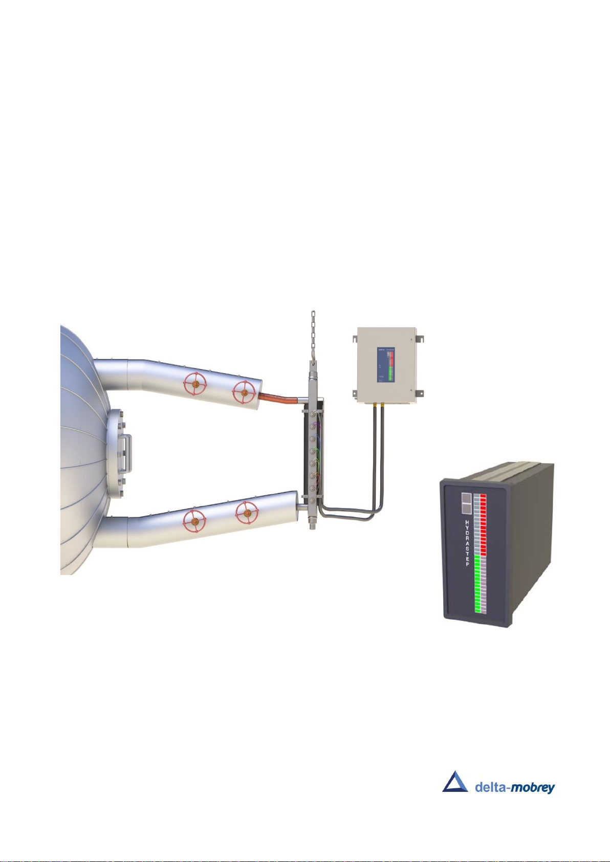
The Hydrastep system is an electronic alternative to the traditional water level gauges on an
industrial steam drum (boiler). Hydrastep's continuous monitoring of steam drums gives an
exceptionally reliable and safe water level indication, high-visibility local and remote displays,
and alarm output trips.
This operating manual is for the single-channel version of the Hydrastep system, which
comprises a controller unit, water column, electrodes, and electrode cabling (Figure 1.3).
The 2468CA** and 2468CC** models of the Hydrastep Control Unit support a single power
supply, up to sixteen level measurement points (electrodes) on a vertical water column, and
a single external level display in the control room.

Introduction
Jan 2022
Operating Manual
24685033, Rev BA
1-2
Hydrastep 2468CA and 2468CC
1.2
HOW IT WORKS
Hydrastep determines the water level from the significant differences between water and
steam electrical resistances in temperatures of up to 560 °C (1040 °F).
A bank of electrodes is installed vertically in a water level column attached by pipework to an
industrial boiler. Electrodes are usually half above and half below the nominal water level
(Figure 1.1), on alternating sides of the water column.
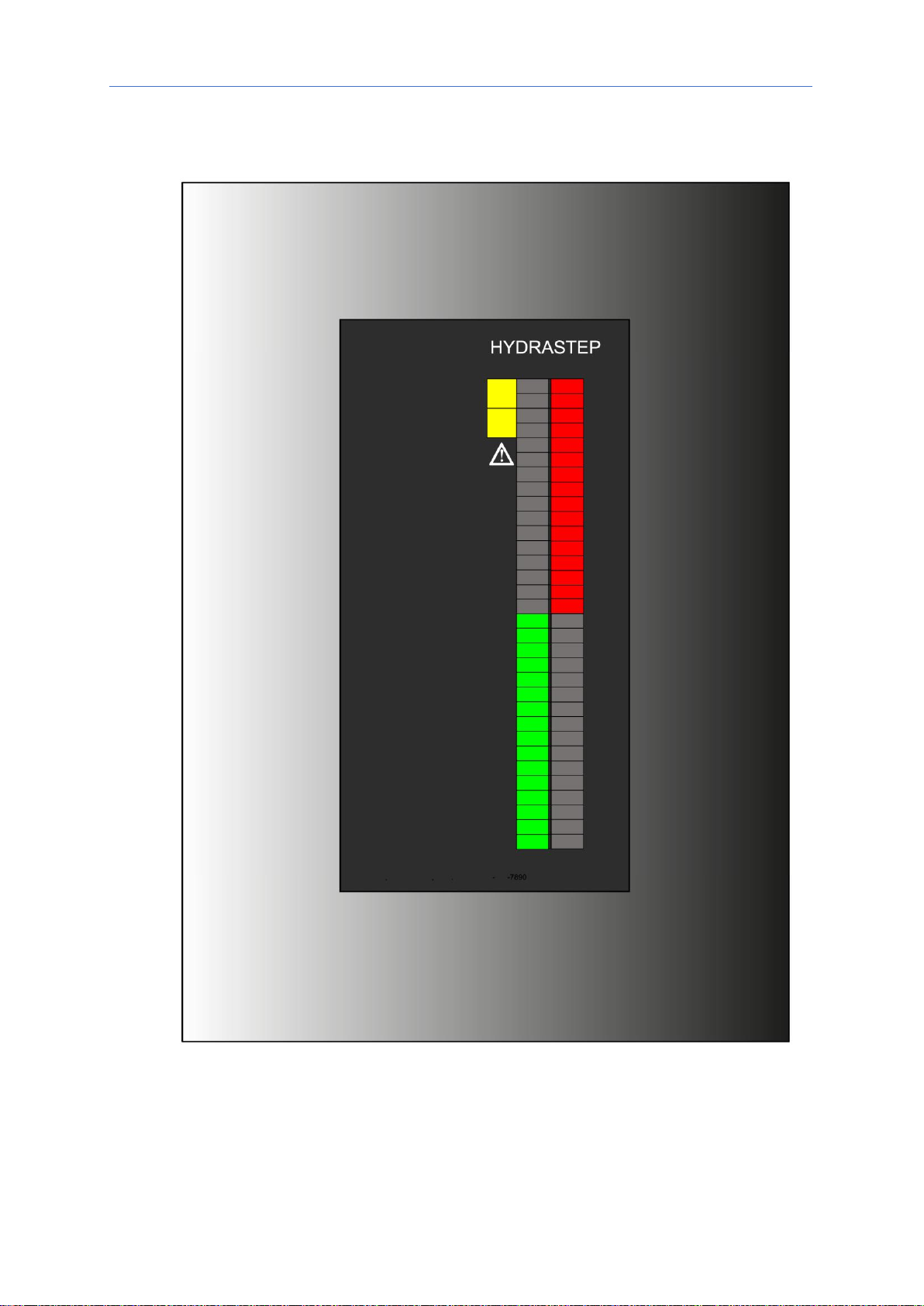
The water and steam levels in a column are indicated by two columns of LEDs on the front
panel display (Figure 1.2). One column of 32 green LEDs indicates which electrodes are in
the water. The other column of 32 red LEDs indicates which electrodes are in the steam.
The electrical resistance is measurable between each electrode's insulated tip and the wall
of the column. A cell constant, defining the actual resistance measured, is determined from
the electrode tip's length and diameter and the column bore. In practice, the chosen cell
constant is such that water resistance is less than 100k ohms, and the steam resistance
exceeds 10M ohms. Since water and steam resistivities are substantially different, the
system is simple and requires no setting up adjustments. It is not susceptible to power
supply variations or ambient temperature changes, resulting in a highly reliable system.
Figure 1.1 - Schematic of resistance measuring cell and electrodes
Operating Manual
24685033, Rev BA
Introduction
Jan 2022
1-3
Hydrastep 2468CA and 2468CC
Figure 1.2 - Front panel of the Hydrastep controller unit
Introduction
Jan 2022
Operating Manual
24685033, Rev BA
1-4
Hydrastep 2468CA and 2468CC
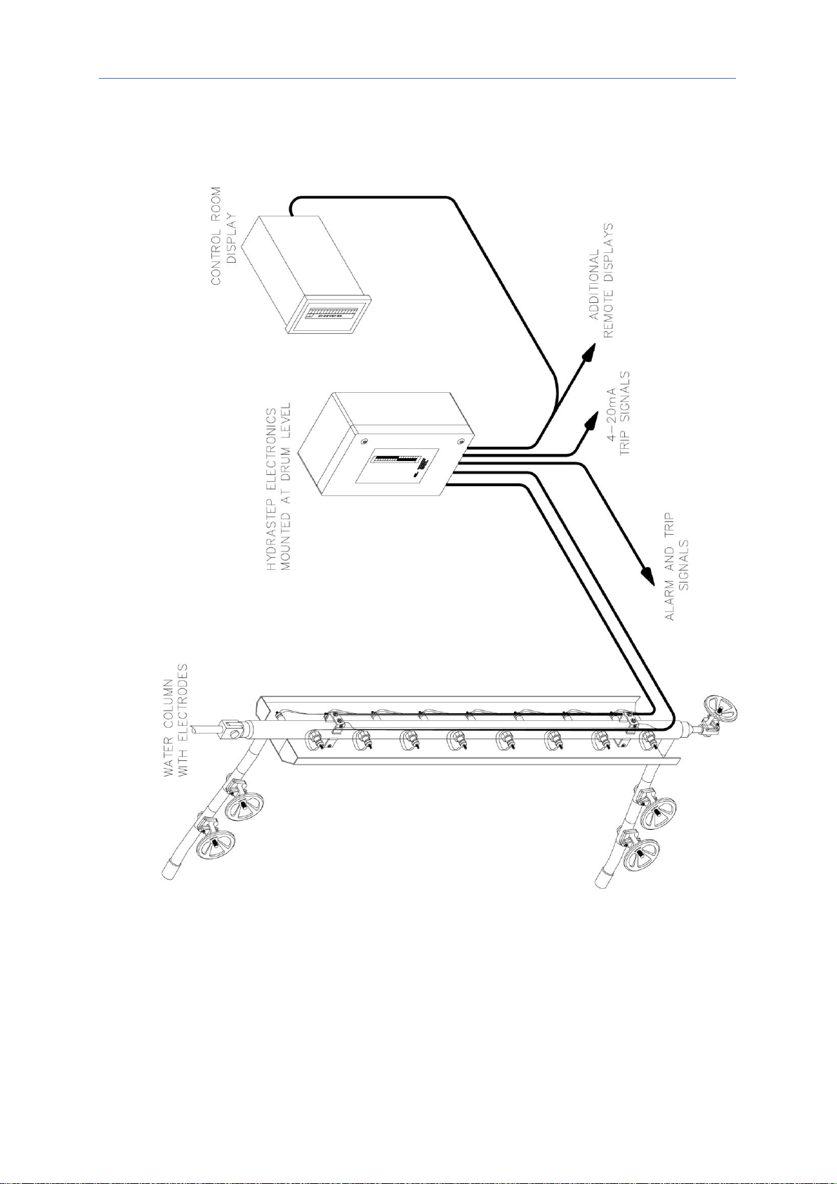
Figure 1.3 - Typical Hydrastep 2468 system installation

Operating Manual
24685033, Rev BA
Introduction
Jan 2022
1-5
Hydrastep 2468CA and 2468CC
1.3
ELECTRONICS IN THE CONTROLLER UNIT
Printed Circuit Boards (PCBs) inside the controller unit are replaceable and upgradable to
expand the capabilities whenever an installation requires it (see Table 1-1).
Input and output boards can all be changed. Additional level displays, Remote Display Units
(RDUs), can be added at any time and connected using standard or fibre optic cabling.
Table 1-1: Upgrade options for controller units 2468CA** and 2468CC**
Control unit
PCB configuration
PCB upgrade path
2468CA**
Input board (ac) –always one fitted
Up to two input boards (ac) (1)
Display board –always one fitted
No upgrade option
Relay Output board –optional
Up to two output boards of either type can be
fitted, giving a maximum of eight relays
Time-delay relay output board –optional
2468CC**
Input board (dc) –always one fitted
Two input boards (dc)
(2)
Display board –always one fitted
No upgrade option
Relay output board –optional
Up to two output boards of either type can be
fitted, giving a maximum of eight relays
Time-delay relay output board –optional
1
Upgrade provides an additional power supply (ac mains) and an extra sixteen level measurement points (electrodes).
It changes a 2468CA** model to the 2468CB** model, i.e., a dual-channel version of Hydrastep.
See operating manual 24685034 for instructions on the 2468CB** model.
2
Upgrade provides an additional power supply (24 Vdc) and an extra sixteen level measurement points
(electrodes). It changes a 2468CC** model to the 2468CD** model, i.e., a dual-channel version of Hydrastep.
See operating manual 24685034 for instructions on the 2468CD** model.
1.3.1 Input board
An Input board supplies power to Hydrastep and processes input signals from 8, 10, 12, 14
or 16 electrodes. Board functions include fault analysis and one analogue output.
A single power supply Hydrastep system has one Input board installed. In Figure 1.4, the
right-hand side of the baseplate has a single Input board mounted.
The Input board is available as Ac (Mains) and Dc supply versions.
Input board
PCB number
Ac (mains) supply
24680501
Dc supply
24680516
Hydrastep uses 18-core cables to connect up to 16 electrodes to the Input board.
The ready-made cable consists of nine pairs of coloured cores. Each electrode requires a
coloured pair of cores. One core is for the signal drive, and the other core is for the signal
return. Black cores are for earth (ground) terminations.
Number of electrodes
Number of cables required
8
1
10 to 16
2
See Chapter 3 for further information.

Introduction
Jan 2022
Operating Manual
24685033, Rev BA
1-6
Hydrastep 2468CA and 2468CC
Note
The terminology used in this manual refers to the lowest electrode as "EL.1", the next
highest as "EL.2", and so forth. A water column has electrodes positioned on opposite sides,
alternating as in Figure 1.1.
The analogue output function provides a continuous electrical signal representing the
measured water level in the column. Switches on the board configure options for the mA
range. See Chapter 3 for how to configure the analogue output to use a different mA range.
1.3.2 Display board
The Display board drives the 32 red (steam) and 32 green (water) LEDs, and the yellow
(fault) LED, visible through the viewing window of the hinged lid. In Figure 1.4, the rear of
the hinged lid shows a Display board mounted. LEDs protrude through the front panel
aperture.
The board uses power and electrode data from the Input board. Data is decoded and used to
illuminate the required LEDs, and transmitted in a serial format to remote displays.
Up to six Remote Display Units (RDUs) can duplicate the front panel display. However, a
Hydrastep controller unit can power only one remote display. Additional remote displays
must be locally powered. See Appendix D for installation information.
Display board
PCB number
Standard LED display
24680515
Note
The number of illuminated LEDs is dependent on the number of electrodes connected to the
Input board. A Hydrastep controller unit illuminates two LEDs per connected electrode.
Unused LEDs are at the bottom of the display when not all electrodes are in use. A blanking
panel is available to mask the unused LEDs.
1.3.3 Output boards (optional)
The Output option boards provide high and low water level alarm and trip facilities for the
Hydrastep system. Four to eight relays can be made available for each Input board fitted.
A requirement in regulations concerning steam-raising plant is provisioning an automatic low-
water-level shutdown or trip device. In Hydrastep, the Relay Output board provides the
required output signals for external devices. In practical applications of shutdown systems,
two factors must be considered: the consequences of spurious trips and the non-availability
of a trip when required, due to protection system faults.
Up to two Relay Output boards of any type can be fitted to an Input board. The option boards
are mounted to the Input board using supplied nylon pillars. See Chapter 3 for further
information.
Output board
PCB number
Relay
24680504
Relay + time delay
24680516

Operating Manual
24685033, Rev BA
Introduction
Jan 2022
1-7
Hydrastep 2468CA and 2468CC
Figure 1.4 –Position of boards in the Hydrastep Controller Unit


2-1
Hydrastep 2468CA and 2468CC
Operating Manual Mechanical Installation
24685033, Rev BA Jan 2022
2
Mechanical Installation
2.1
WATER COLUMN AND ELECTRODES INSTALLATION
Always install the water column and electrodes before the controller unit. See Appendix E.
2.2
CONTROLLER UNIT INSTALLATION
The recommended location for the Hydrastep Controller Unit is a wall or vertical bracket
structure meeting the following criteria:
▪Easy access for viewing the front panel display and for servicing
▪Safety assessed for supporting four times the weight of the mounted equipment
(see Appendix B for the weight specifications)
▪Not too far from the water column for electrode cables to reach it
The controller unit has four welded feet for securing it in a vertical position. Using a
template derived from the dimensional details given in Figure 2-1, drill the four holes in
the prepared surface. Secure the unit with M10 bolts or equivalent fixings.
Cables enter the controller unit through a gland plate at the base (Figure 2-1).
The plate is blank, ready to be drilled, for the type of glands and gland configuration required
for your installation. Alternatively, use trunking for direct cable entry.
Chapter 3 explains the cabling required and how to connect them to the electronic boards in
the controller unit.
Note
▪The gland plate is removable to make it easier for drilling holes within the useable area
▪Use a good-quality RF cable gland for compliance with the EMC regulations in Europe.
The gland should establish a good annular (ring-shaped) connection to the cable screen
(shield).
▪An installation using unscreened cables or trunked routing without a gland plate and RF
gland would not be covered by the manufacturer’s EMC declaration of conformity.

2-2
Hydrastep 2468CA and 2468CC
Mechanical Installation Operating Manual
Jan 2022 24685033, Rev BA
Figure 2-1: Installation diagram for the Hydrastep 2468 Controller Unit
2.3
REMOTE DISPLAY UNIT INSTALLATION
See Appendix D for mechanical installation instructions.
This manual suits for next models
1
Table of contents
Other delta-mobrey Measuring Instrument manuals


