SONOPAN NDTM-10 User manual
RADIOMETER PHOTOMETER
NDTM-10
INSTRUCTION MANUAL
PPUH SONOPAN Sp. z o.o.
ul. Ciołkowskiego 2/2
15-950 Białystok, Poland
phone/fax: +48 85 742 36 62
http://www.sonopan.com.pl
July 2017

– 2–
TABLE OF CONTENTS
1INSTRUMENT CHARACTERISTIC................................................................................3
1.1 Equipment ...............................................................................................................3
1.2 Construction ............................................................................................................ 3
1.2.1 Measuring probe ..............................................................................................3
1.2.2 Integrating meter .............................................................................................. 4
1.3 Measured quantities................................................................................................4
1.4 Technical data.........................................................................................................4
1.5 Firmware update .....................................................................................................5
2OPERATION .................................................................................................................. 5
2.1 Powering the instrument.......................................................................................... 5
2.2 Battery indicator ......................................................................................................5
2.3 Measure ..................................................................................................................6
2.4 Menu .......................................................................................................................6
2.4.1 Zeroing.............................................................................................................7
2.4.2 Memory ............................................................................................................7
2.4.3 Calibration........................................................................................................7
2.4.4 Setup................................................................................................................ 7
2.4.5 Measuring ranges ............................................................................................8
2.5 Turning off the instrument ....................................................................................... 8
2.6 Calibration procedure .............................................................................................. 8
3COMMUNICATION WITH PC ........................................................................................ 9
4SAFETY DURING MEASURES .....................................................................................9
5RECOMENDATIONS FOR ISTRUMENT USE............................................................... 9
6MAINTENANCE AND REPAIRS .................................................................................... 9
7CE MARKING AND CONFORMANCE TO EU COUNCIL DIRECTIVES ..................... 10

– 3–
1 INSTRUMENT CHARACTERISTIC
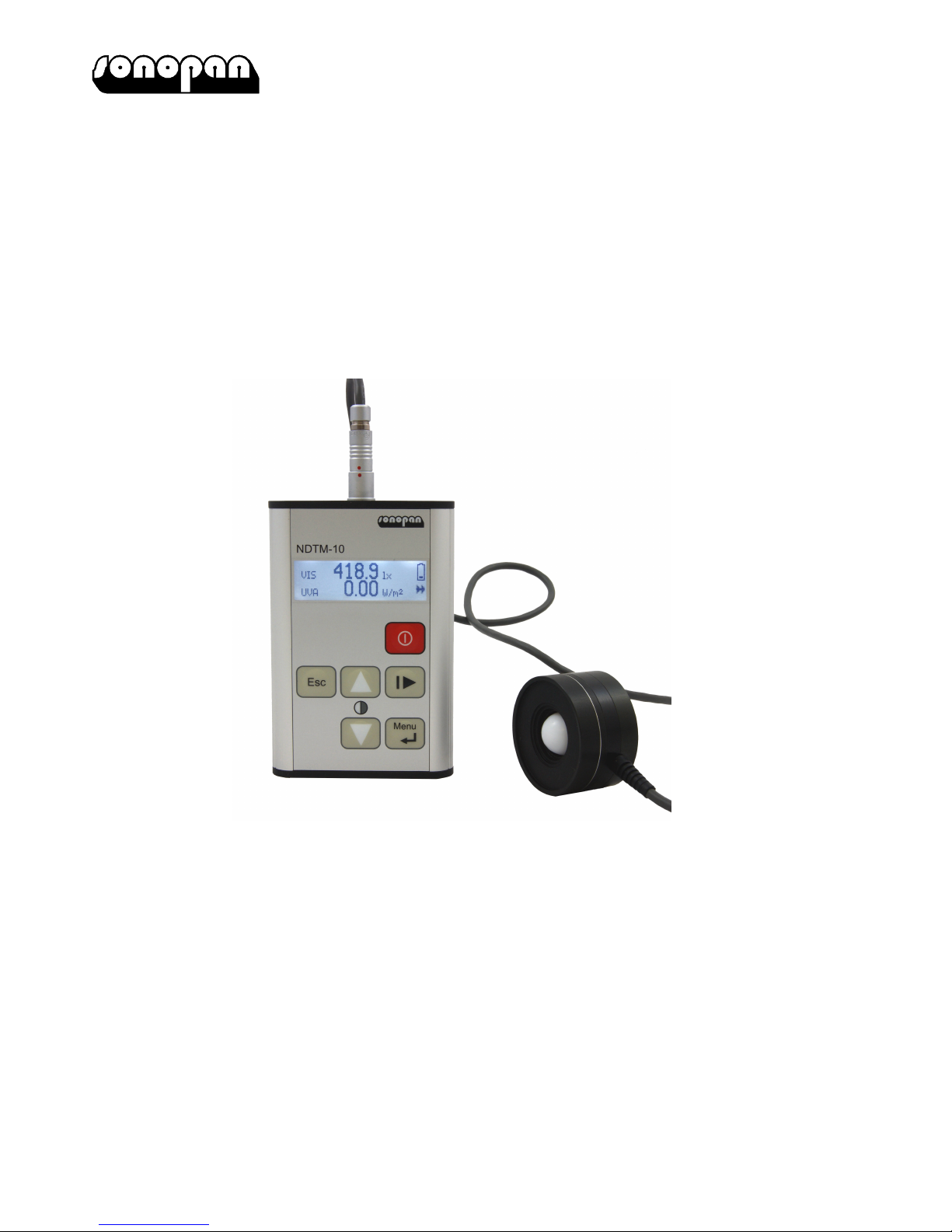
Radiometer-Photometer NDTM-10 is two-channel, integrating meter designed for checking
viewing conditions during non-destructive testing (NDT) by magnetic particle inspection
(MPI) method. That kind of test is used to detecting surface and slightly subsurface
discontinuities in ferromagnetic materials such as iron, nickel, cobalt and some of their
alloys.
The meter has two measuring channels:
• VIS – high quality luxmeter,
• UVA – UV-A range photometer.
Technical specification of the instrument conforms to standards:
• ISO/CIE 19476 Characterization of the performance of illuminance meters and luminance
meters.
• EN ISO 9934 Non-destructive testing – Magnetic particle testing – Part 1: General
principles.
• EN ISO 3059 Non-destructive testing – Penetrant testing and magnetic particle testing –
Viewing conditions.
1.1 Equipment
Basic equipment:
• two-channel measuring probe,
• two-channel integrating meter,
• two LR03 batteries,
• instruction manual,
• warranty card.
Extra equipment:
• photometric probe handle,
• USB cable.
1.2 Construction
1.2.1 Measuring probe
Measuring probe’s input window is common to both channels, what provides the same
directional characteristic and doesn’t introduce additional error resulting from detectors shift
for small measuring distances.
The position of reception plane, with respect to which distance between source and probe is
measured, is marked on the cylindrical surface of the probe by white dash (8.3mm from the
front surface).
of measuring probe's reception plane
white line indicating the position
Fig.1. The position of measuring probe’s reception plane.

– 4–
1.2.2 Integrating meter
Keyboard and LCD screen is located on the front panel of the meter. Measuring probe
socket is on the top panel, battery compartment and mini USB socket are on the bottom
panel. USB socket can be used to firmware update and meter control.
1.3 Measured quantities
NDTM-10 meter allows a simultaneous measurement of:
• illuminance (VIS channel),
• UV-A irradiance (UVA channel).
The result of the single measure is 1 second average value. Measured values are displayed
on LCD with resolution specified in 1.4 Technical data, reduced to 4 oldest significant digits.
1.4 Technical data
UVA channel VIS channel
Spectral matching according to EN ISO 3059
V(λ) CIE
• matching quality ∆λ1/10 320 – 395nm f1' 2) ≤3%
∆λ1/2 337 – 385nm
λmax 365nm
Sλ=313nm < 5%
Sλ=405nm < 0.5%
Direction matching
• matching quality
cosine
f21) ≤3%
cosine
f22) ≤ 3%
Nonlinearity f31) ≤0.5% f32) ≤0.5%
Measuring range 3) 100 W/m2(10 mW/cm2) 10 000 lx
Resolution 0.01 W/m2(1 µW/cm2) 0.1 lx
Measurement memory 20 cells
Power supply 2x LR03 batteries (1.5V, AAA size)
Environmental conditions
• temperature
• relative humidity
-10 ÷+50°C
90% (without condensation)
Dimensions
• meter 107×72×19mm (without measuring probe socket)
• measuring probe Ø44 x 25.5mm
• measuring probe cable length 1.5m
Weight with measuring probe and
batteries
335g
1) Characterizing the Performance of Integral Measuring UV-Meters. Final Report of WG1 Thematic Network
for Ultraviolet Measurements. November 2000.
2) ISO/CIE 19476 Characterization of the performance of illuminance meters and luminance meters.
3) Minimum value guaranteed by manufacturer. Real value depends on sensitivity of used detector.

– 5–
Fig.2. Relative spectral sensitivity of both VIS and UVA channels.
1.5 Firmware update
NDTM-10 firmware can be updated by user. Update procedure is as follows:
• Download SonBoot application from the manufacturer’s website.
• Download NDTM-10 firmware from the manufacturer’s website.
• Connect the meter to PC by USB cable.
• Wait for proper drivers installation.
• Run SonBoot application.
• Select NDTM-10 from the “Device type” list
• Select connected meter from “USB Device” list
• Open firmware file.
• Turn on the meter.
• Push “Program” button.
2 OPERATION
2.1 Powering the instrument
Before turning on the instrument, two AAA size batteries should be placed in the battery
compartment according to the polarity marked on the back panel of the meter. High capacity
alkaline batteries should be used, i.e. LR03 type. The meter turns on by pushing and hold
for a while button . After turning on, meter name and firmware version is displayed on
the LCD screen. That screen will disappear after about 15 seconds or after pushing any
key. On welcome screen pushing buttons enters set contrast menu (look at:
2.4.4.1 Contrast).
After welcome screen disappears results screen is displayed. Result screen contains:
• VIS channel measured value, expressed in lux,
• UVA channel measured value, expressed in W/m2or W/cm2depends on user setting
(look at: 2.4.4.4 UVA unit),
• battery indicator,
• RUN / PAUSE indicator.
2.2 Battery indicator
Battery indicator is displayed in the top right corner of the results screen:
• battery full,
• battery partially discharged,

– 6–
• battery discharged,
• battery discharged to critical level – meter can automatically power off in any time,
• meter power supplied from USB port (look at: 3 COMMUNICATION WITH PC).
2.3 Measure
The measurement starts and pause using button . RUN / PAUSE indicator is displayed
in the bottom right corner of the results screen::
• measure paused, last measured values are presented,
• measure is running, current measured values are presented.
Measured results from both channels are displayed with measured units. Also, unit prefixes
are used::
• µ "micro" ×10–6,
• m "milli" ×10–3,
• k "kilo" ×103,
• M "mega" ×106.
In the case of measuring range overload, overload indicator is displayed in front of
measured value. Overload is signaled when at least one actual value of the one second
average is higher than measurement range. In that case, average value can be much less
than high limit of measured range but it is saddled with significant error.
2.4 Menu
To change parameters and settings of the meter hierarchical menu system was developed.
Menu is organized as follows:
• Zeroing
• Memory
•• Save
•• Load
••• Results
•• Erase
• Calibration
•• VIS
•• UVA
• Setup
•• Contrast
•• Autooff
•• Backlight
•• UVA unit
••• W/m2
••• W/cm2
•• Language
••• Polish
••• English
• Measuring ranges
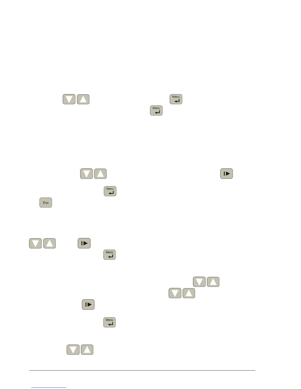
Menu is called by pushing button . Buttons are used to menu navigation.
Button confirms the choice, button is used to back to previous level of menu or
cancel. If the number of menu items don’t fit the on the screen, indicators appear to
inform about invisible positions.
– 7–
2.4.1 Zeroing
That option is used to detectors’ dark current and measurement channel offset voltage
compensation to set indication to zero when there is no input signal in both channels.
CAUTION: Zeroing can be started only when measuring probe is covered. Otherwise,
measured results will be inaccurate.
2.4.2 Memory
The instrument is equipped with a measurement memory. Using the memory is possible
from menu system level, by submenus: save, load, erase. Once you have selected one of
the three available options, you will see a list of memory cells.
The list shows the illuminance and irradiance values in the cell, or "none" if the cell is empty.
Use the keys to select an active memory cell. performs a save, load or
erase operation. In erase submenu, using button when empty cell is selected erase all
measurement memory (this operation requires additional confirmation in the dialog box
shown).
2.4.3 Calibration
This menu allows to check calibration factors and to adjust indicated value by changing that
calibration factors in both channels. After entering the menu, calibration factors for both
channels are displayed. Measuring channel should be selected. On the next screen current
measured value is displayed. This number should be edited to obtain proper measured
value, using buttons to change digit value or unit prefix and button to select
active digit and unit prefix. After pushing button, old and new calibration factors are
displayed. Another pushing of button accept changed calibration factor value. Pushing
key in any time cancels adjustment and back to the main adjustment menu.
2.4.4 Setup
2.4.4.1 Contrast
In this menu LCD contrast can be adjusted. Changing of contrast is made using buttons
. Button turns backlight on and off during regulation. New contrast setting
can be accepted using button .
2.4.4.2 Autooff function
This setting allows to save battery life. When the option is turned on, instrument will be
switched off after set time from last pushing of any button. Buttons are used to
turn the function on or off. Autooff time can be set using buttons to change
value of the digit and button to change active digit when the function is ON. Time is
set in format: hh:mm:ss (hours, minutes, seconds). The minimal time is 30s. New setting
can be accepted using button .
2.4.4.3 Backlight
This menu allows to manage meters’ backlight. There are three options, which can be
changed using buttons:
• On – backlight always on (shortest battery life),
• Off – backlight always off (maximum battery life),
– 8–
• Auto – backlight on during set time after button pushing (compromise between user’s
comfort and battery life).
After choosing position "Auto", time can be set using buttons to change value of
the digit and button to change active digit. Time is set in format: hh:mm:ss (hours,
minutes, seconds). New setting can be accepted using button .
2.4.4.4 UVA unit
In this menu irradiance units can be changed. Available possibilities:
• W/m2,
• W/cm2.
The choice is performed using buttons and new setting can be accepted using
button .
2.4.4.5 Language
In this menu language of the menu can be changed. Available possibilities:
• Polish,
• English.
The choice is performed using buttons and new setting can be accepted using
button . Language is changed “on the fly”, just after selecting a new one.
2.4.5 Measuring ranges
This menu allows to check of real measuring ranges for both VIS and UVA channels. These
measuring ranges are strictly connected with calibration factors and are result of varied
sensitivity of used detectors (look at: note 3) in section 1.4 Technical data).
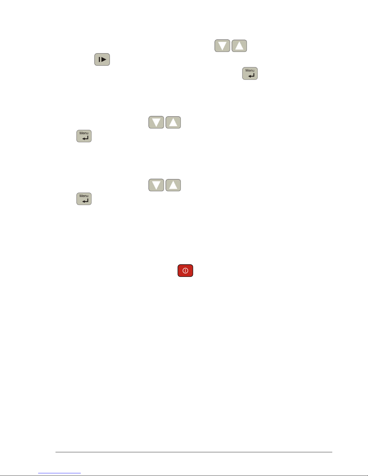
2.5 Turning off the instrument
To turn off the instrument push and hold button for at least 2 seconds.
2.6 Calibration procedure
Calibration is the process of finding a relationship between two quantities, one of which is
standard value and second one which is unit under test. After calibration adjustment can be
made, to adjust the indication of the instrument to the applied standard value. Calibration
(including adjustment) should be conducted not less than once a year.
Calibration procedure:
• Place proper standard on photometric bench (illuminant A for VIS channel or 365nm
monochromatic source for UVA channel).
• Place measuring probe in the axis of the radiation source.
• Calculate proper value of illuminance or irradiance, using standard value and measured
distance between probe’s reception plane (look at: 1.2.1 Measuring probe) and the
source, or measure that value using reference meter.
• Using NDTM-10 meter, measure illuminance / irradiance.
Adjustment procedure:
• Enter to meter’s menu and select option Calibration.
• Select proper channel.
• Enter previously calculated or measured proper value of measured quantity and accept a
new calibration factor (look at:2.4.3 Calibration).

– 9–
3 COMMUNICATION WITH PC
NDTM-10 is equipped with mini USB socket for PC connection. After first connection, proper
drivers should be installed by system. This communication interface can be used to
firmware update (look at: 1.5 Firmware update) or unit control using dedicated software.
After connection of USB cable, meter turns on automatically and is powered from USB port.
Then meter cannot be turned off using keyboard. Meter turns off after USB cable
disconnecting.
4 SAFETY DURING MEASURES
NDTM-10 instrument is designed to ultraviolet radiation measurement which is dangerous
for human health. Special care should be taken during measurement, eyes and skin
protections should be used to reduce ultraviolet radiation dose.
During using NDTM-10 meter to non-destructive testing it is essential to follow the
recommendations contained in section 5 of EN ISO 9934-1 standard.
5 RECOMENDATIONS FOR ISTRUMENT USE
• It is not recommended to expose instrument on falls, shakes neither on any other factors
that might cause mechanical damages.
• Protect instrument from excessive moisture and aggressive chemical agents that may
damage the meter.
• The measuring probe cover should be removed only at the time of the measurement.
• In the case of dirty measuring probe dome, unscrew the stepped ring, as shown on the
picture below, and clean it with a soft cloth dampened with clean alcohol
Fig.3. Access to the measurement probe dome.
• In the case of overload of any channel, remove measuring head from the measuring field
or cover the probe. Prolonged exposure with strong radiation can damage detectors.
• The instrument should be stored and transported in factory case.
• In the case of longer storage, remove batteries from the instrument.
6 MAINTENANCE AND REPAIRS
Radiometer-photometer NDTM-10 requires no special maintenance treatments.
Any repairs have to be performed by the manufacturer of the instrument.

– 10 –
7 CE MARKING AND CONFORMANCE TO EU COUNCIL
DIRECTIVES
The product described in this instruction conforms to following EU Council Directives:
2004/108/EC Electromagnetic compatibility.
The conformance to above-mentioned requirements is confirmed by CE mark.
This product cannot be thrown away with household waste. Deposit the
product in an authorized electrical and electronic waste collection area for
recycling. Contact local Municipal Bureau or nearest waste disposal company
to get more detailed information.
Table of contents
Other SONOPAN Measuring Instrument manuals


Popular Measuring Instrument manuals by other brands

Moeller
Moeller ZEV-XSW-820 installation instructions

Opsytec Dr. Grobel
Opsytec Dr. Grobel RM-32 operating instructions

Sontex
Sontex Superstatic 440 Installation and manual

Nieaf Instruments
Nieaf Instruments NI 16R manual

Extech Instruments
Extech Instruments UV505 user manual

Desco
Desco 19494 Operation and maintenance instructions


