Delta OHM HD2817T Series User manual

1
Our instruments’ quality level is the results of the product continuous development. This can bring about
differences between the information written in this manual and the instrument that you have purchased. We
cannot entirely exclude errors in the manual, for which we apologize.
The data, figures and descriptions contained in this manual cannot be legally asserted. We reserve the right
to make changes and corrections without prior notice.
HD2817T...
ENGLISH
REV. 1.2
28th Nov. 2011

2
HD2817T…
Transmitter, indicator, ON/OFF regulator,
temperature and humidity datalogger
The HD2817T... series instruments are transmitters, indicators, ON/OFF regulators with
datalogger function. They measure temperature and humidity.
They are fitted with an LCD backlit graphic display 128x64 pixel.
The main characteristic of these instruments is the interchangeable probe. The user can
virtually change the probe without interrupting the process. Then the probe can be calibrated
or repaired.
We have models with horizontal (S.TO), vertical (S.TV) or separate (S.TC) probes, connected
to the instrument using cables of different lengths. The S.TO and S.TV probes are made of
AISI304 steel, the S.TC probes can be made of AISI304 steel or POCAN plastic material.
To measure the dew point in compressed air systems, the probe S.TC2.480.2 can be
connected to the HD2817T...
The probe, factory calibrated and ready for use, is fitted with a SICRAM2 module storing its
calibration information and allowing its interchangeability.
The devices measure:
Temperature in Celsius or Fahrenheit degrees
Relative humidity
and calculate:
Absolute humidity
Mixing ratio
Dew point
Wet bulb temperature
All models are fitted with current or voltage analogue outputs.
We supply models with two working relays and an alarm relay, user configurable.
All models have a multistandard RS232/RS485 output and an auxiliary RS232C serial output.
You can connect several network devices through the RS485 serial port.
The HD2817T... models use a wide LCD backlit graphic display (128x64 pixel) showing three
physical quantities simultaneously or a real time graph of any of the measured quantities.
The datalogger function allows recording of the measurements detected by the instrument,
according to a frequency set by the user.
The instrument configuration is permanently stored. The internal clock is protected against a
mains power failure by a special Lithium battery.
When making the order, you can select the power supply between 24Vac/dc or universal
90...240Vac.

3
1. Instrument versions and available probes
Relay
HD2817Tx-D0
None
HD2817Tx-DR
2 working relays with exchange contact,
1 alarm relay with normally open contact.
Type of probe
HD2817T.xx
Instrument with vertical probe S.TV or probe with cable S.TC.
HD2817TO.xx
Instrument with horizontal probe S.TO.
Probes complete with SICRAM2 module for HD2817T.xx instruments
S.TV
Vertical probe L = 130 mm
The material of the S.TC... series probe can be chosen between AISI304 steel or POCAN
plastic material.
S.TC1.2
Probe L = 135 mm with 2 m cable
S.TC1.2P
Probe L = 135 mm with 2 m cable in POCAN
S.TC1.5
Probe L = 135 mm with 5 m cable
S.TC1.5P
Probe L = 135 mm with 5 m cable in POCAN
S.TC1.10
Probe L = 135 mm with 10 m cable
S.TC1.10P
Probe L = 135 mm with 10 m cable in POCAN
S.TC2.2
Probe L = 335 mm with 2 m cable
S.TC2.2P
Probe L = 335 mm with 2 m cable in POCAN
S.TC2.5
Probe L = 335 mm with 5 m cable
S.TC2.5P
Probe L = 335 mm with 5 m cable in POCAN
S.TC2.10
Probe L = 335 mm with 10 m cable
S.TC2.10P
Probe L = 335 mm with 10 m cable in POCAN
Probe with cable for measuring humidity in pipes
S.TC2.480.2
Cable length 2m.
Measuring range: -40…+60°C, -40…+60°C DP.
1/4" Italian standard Quick-fit. Working pressure up to 16bar.
Measuring chamber in AISI 304.
Probes complete with SICRAM2 module for HD2817TO.xx instruments
S.TO1
Horizontal probe L = 135 mm
S.TO2
Horizontal probe L = 335 mm

4
2. Upon first start up
Some notes about first start up are reported below. For the details see the various chapters
in the manual.
Before turning on, the probe should be connected to the instrument.
Apply the correct voltage to the instrument. A wrong voltage can cause permanent damages
to the instrument that are not covered by the warranty.
In order to install and connect the instrument, please see the chapters “Installation and
connection” and “Terminal board description”.
To use the analog outputs and relays, please see the chapters “Current and voltage analog
outputs” and “Instruments fitted with relay outputs”, respectively.
For the connection to a PC or network of instruments, please see the charter “Serial
communication and instrument network”.
Check the instrument date and time as described in the following chapter.
3. Initial setting or date and time update
When you power up the instrument, the date and time check takes about one minute.
The following screen will appear:
2008/01/01 12:00:00
TIME/DATE
year/mm/dd hh:mm
2008/01/01 12:00:00
<UP> <DOWN> change
<ENTER> confirm
<ESC> exit
The date and time are correct: press MENU to go directly to measurement mode.
The date and time are not correct:
1. Use the arrows to modify the year, already selected, and press ENTER.
2. You will get to the month setting. Change it using the and arrows and confirm
with ENTER.
3. Repeat for the other items: day, hour, minutes. After the last confirmation you will
exit the setting page and return to the menu main screen.
4. Press MENU to return to measurement mode.
For the next date and time setting, please see the “TIME/DATE” menu item description in the
chapter “Description of the menu”.

5
4. Description of the display
The display constantly shows three measurements (lines 3, 4 and 5 in the figure)
associated to the A1, A2 and A3 analog outputs, respectively:
the physical quantity associated to the analog output A1 is shown on line (3),
the physical quantity associated to the analog output A2 is shown on line (4),
the physical quantity associated to the analog output A3 is shown on line (5).
Each line can show relative humidity, absolute humidity, mixing ratio, dew point, wet bulb
temperature or temperature.
The temperature can be expressed in Celsius or Fahrenheit degrees.
The first display line (1) shows the current date and time.
The auxiliary indications are shown on line (2): e.g. MAX, MIN or AVG functions when pressing
the FUNC key activating the maximum, minimum and average measurements.
To change the temperature unit of measurement between Centigrade or Fahrenheit, press the
UNIT key.
To show a physical quantity in one of the three lines, you can use the “Conf. OUT” >>
“Output Analog 1-2-3” >> “Analog Output x” menu item, with x = 1, 2 or 3.
Procedure:
1. Press the MENU key. The main menu opens.
2. Use the arrows to select “Conf_OUT” and confirm with ENTER.
3. Use the arrows to select “Output Analog 1-2-3” and confirm with ENTER.
4. Use the arrows to select “Current/Voltage out” and confirm with ENTER.
5. Use the arrows to select the type of analog output: “4...20mA/2...10Vdc” or
“0...20mA/0...10Vdc”. Confirm by pressing ENTER. The asterisk will indicate your new
selection. Press ESC to return to the previous menu;
6. Use the arrows to select one of the three analog outputs and confirm with ENTER.
The analog output 1controls the physical quantity shown on line (3), the analog output 2
on line (4) and the analog output 3 on line (5).
7. A screen with two items will appear: “Mode” and “Range values”.
8. Use the arrows to select “Mode” and confirm with ENTER.
9. Use the arrows to select the physical quantity to be associated to the analog output
and confirm with ENTER:
RH Rel. Humidity corresponds to relative humidity,
AH Abs. Humidity corresponds to absolute humidity,
MR Mixing ratio corresponds to mixing ratio,
Td Dew Point Temp. corresponds to dew point,
T Temperature corresponds to temperature,
TW Wet bulb temp. corresponds to the wet bulb temperature.
The asterisk will indicate your new selection. Press ESC to return to the previous menu.

6
10. Use the arrows to select “Range values” and confirm with ENTER.
11. The “Scale low value” (lower limit of the physical quantity) item will blink: if necessary,
change it using the arrows and confirm with ENTER.
12. You will get to the next item “Scale high value” (upper limit of the physical quantity): if
necessary, change it using the arrows and confirm with ENTER.
13. Press ESC to exit.
14. If necessary, set the other two analog output, repeating the steps from 6 to 13.
15. Press MENU to return to measurement mode.

7
5. Keyboard description
The HD2817T... models are fitted with an LCD display and an eight-key keyboard.
Vertical ZOOM key
In graphic mode, it enlarges or reduces the graph’s vertical scale.
Horizontal ZOOM key
In graphic mode, it enlarges or reduces the graph’s horizontal scale.
Up arrow
When used in the menu, it selects an item from a list or increases the selected parameter
value.
Down arrow
When used in the menu, it selects an item from a list or decreases the selected parameter
value.
UNIT key
It changes the temperature unit of measurement between Centigrade or Fahrenheit. By
repeatedly pressing the UNIT key, the desired unit of measurement can be displayed.
In graphic mode, it allows selection of a new physical quantity.
ESC key
When used in the menu, it goes up one level in the menu hierarchy from a sub-level to an
upper level. To go directly from any level to measurement mode, press MENU.
ENTER/FUNC key
This key has a double function:
As ENTER key, in the menu, it confirms the selected item.
As FUNC key, in standard view, it enables the MAX (maximum), MIN (minimum), AVG
(average) sequence for the displayed measurement.
To reset the previous measurements and restart with a new calculation, press ENTER/FUNC
until the message “CLR Func?” appears, then use the arrows to select YES and confirm
using ENTER.
MENU key
It allows to access the instrument menu main screen. In the menu, it returns to normal
measurement.
8
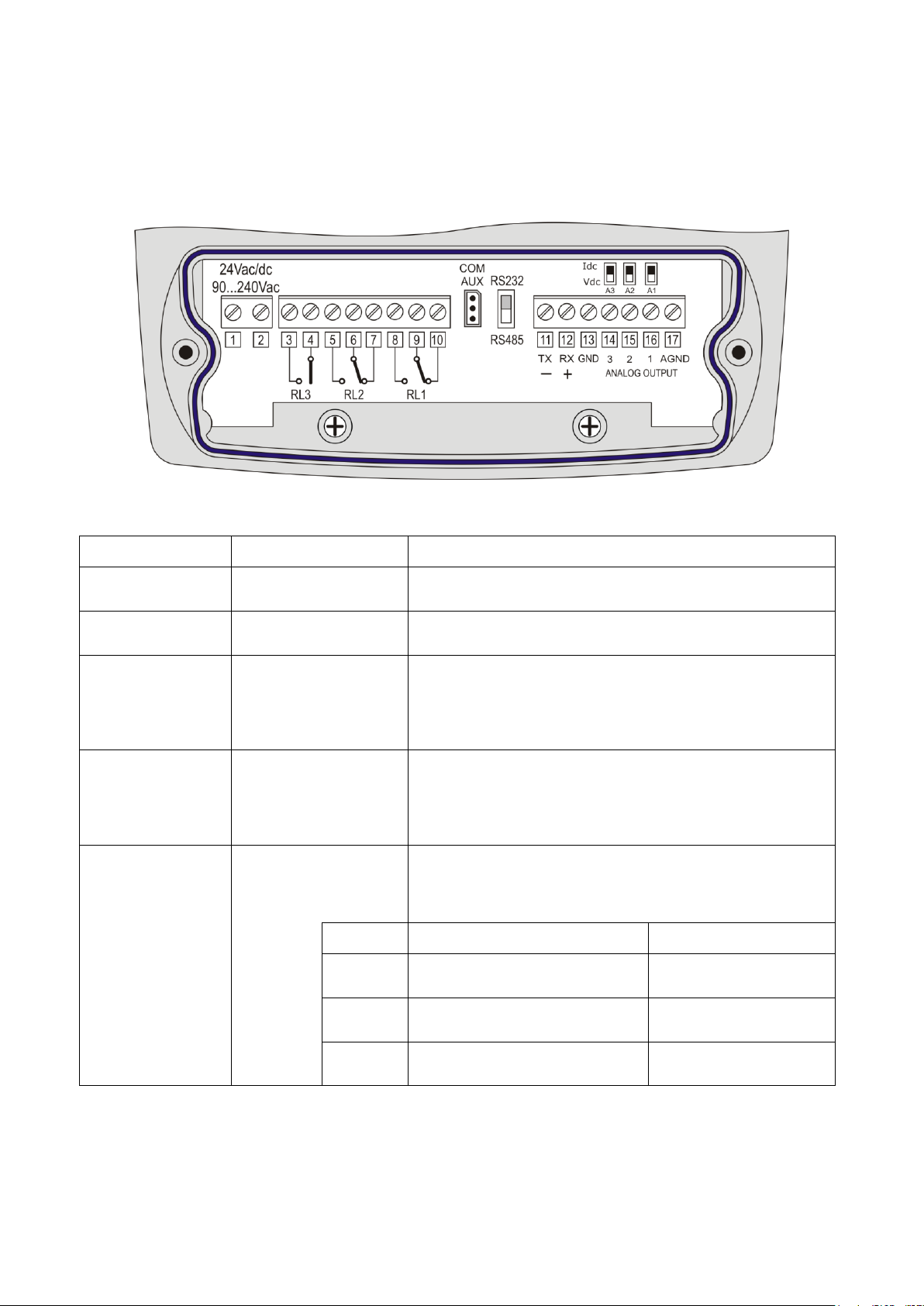
6. Terminal board description
The terminal board is located in the lower part of the instrument, protected against dust and
splashes by two doors: the first external, snap-locked, the second internal, fixed with two
screws.
Number
Function
Notes
1 –2
Power input
When making the order, you can select the power supply
between 90...240Vac or 24Vac/dc
3 –4
Alarm relay RL3
For the settings, please see the chapter “Instruments
fitted with relay outputs”
5 –6 –7
Working relay RL2
The relay can be associated to any quantity measured by
the instrument (relative humidity or correlated
measurements, temperature).
For the settings, please see the chapter “Instruments
fitted with relay outputs”
8 –9 –10
Working relay RL1
The relay can be associated to any quantity measured by
the instrument (relative humidity or correlated
measurements, temperature).
For the settings, please see the chapter “Instruments
fitted with relay outputs”
11 –12 –13
RS232C or RS485
serial connection
The communication protocol selection (RS232C or RS485)
is performed by using the switch on the left of terminal
11. For the settings, please see the chapter “Serial
communication and instrument network”
Terminal
RS232C mode
RS485 mode
11
To be connected to TX line of
PC (pin 3 of connector DB9)
To be connected to line
B (negative of the pair)
12
To be connected to RX line of
PC (pin 2 of connector DB9)
To be connected to line
A (negative of the pair)
13
To be connected to GND line of
PC (pin 5 of connector DB9)
To be connected to
GND line

9
Number
Function
Notes
14 –15 –16 –17
Current and voltage
analog outputs
The analog outputs can be associated, independently, to
any quantity measured by the instrument: relative
humidity, absolute humidity, mixing ratio, dew point, wet
bulb temperature, temperature.
For the settings, please see the chapter “Current and
voltage analog outputs”.
Terminal
Function
14
Positive output 3. The negative pole is terminal 17.
15
Positive output 2. The negative pole is terminal 17.
16
Positive output 1. The negative pole is terminal 17.
17
A GND negative pole common to analog outputs.
AUX-COM connector
The AUX-COM connector (for cable RS27) is an auxiliary RS232C serial port. It is used to
temporarily connect the instrument to a PC with the DeltaLog12 software.
10
7. Measurement probe and calibration of the relative
humidity sensor
The instrument only accepts SICRAM2 type temperature and relative humidity measurement
probes. These probes are fitted with an electronic circuit that converts the signal and stores
their calibration information.
Thanks to their factory calibration, the probes are interchangeable, directly and immediately.
The probes can be sent to our factory for calibration or repair.
Saturated solutions are available for the humidity probe’s checking and calibration.
For the calibration of the humidity sensor, DeltaLog12 software is to be used: see procedure
reported in the software’s instruction manual.
The calibration of the temperature sensor by the user is not required.
The interchangeable probe allows reducing the instrument down time virtually to zero, in case
of faulty probe.
The replacement can be performed without stopping the activity, thanks to the “suspend”
functioning mode.
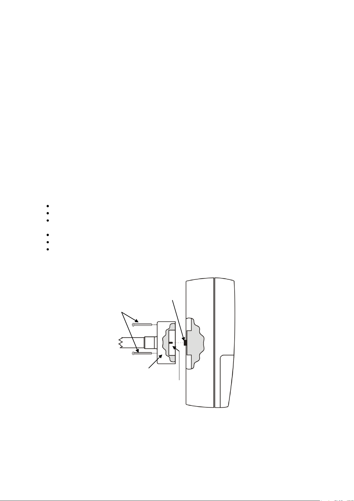
In the HD2817TO.xx models, the probe is fixed on the instrument back using three
screws.
To replace the horizontal probe:
Start the suspend function.
Unscrew the three screws fixing the probe housing module to the instrument.
Extract the probe from the instrument connector: the probe to be replaced can be
removed.
Connect the new probe to the instrument.
Fix the module to the instrument back using the three screws.
The replacement is complete.
Note: if necessary, the suspension time can be reset to 60 seconds by pressing the arrow.
Module mounting screws
Probe housing module
Female connector
Male connector
11
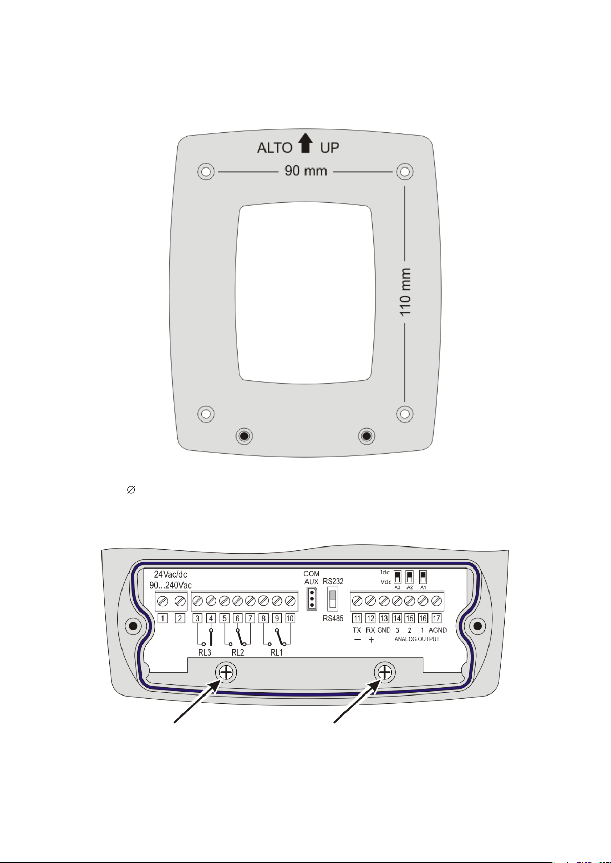
8. Installation and connections
The instrument is set to work indoors.
For wall mounting, the instrument is fitted with a plate to be fixed to the wall. The instrument
is attached through a cavity, near the arrow.
As shown in the figure, 4 holes are needed at 90 mm horizontally and 110 mm vertically. The
holes have a 4,5 mm diameter.
In order to separate the plate from the instrument bottom, open the two front doors to access
the instrument terminal board. Unscrew the two screws shown in the following figure and pull
the instrument toward yourself.
Fix the plate to the wall using four screws. Lock the instrument in the cavity located at the top
and screw again the two screws inside the terminal board housing for final fastening.

12
9. Menu description
The MENU key allows accessing the set of items that regulate the instrument functioning.
The menu is nest-structured: with main categories and submenus.
To select a menu item, use the arrows until you select the item to be modified: using
ENTER you can access the selected item.
To move up one level from any point in the menu, you can press ESC.
To exit the menu and return directly to measurement, press MENU.
In measurement mode, the MENU key is used to access the menu main screen.
2008/01/31 12:00:00
MAIN MENU
Info
Time/Date
Logging
Conf. OUT
Serial
View mode
SW Reset
Stand-by
Contrast
<ESC> exit
13
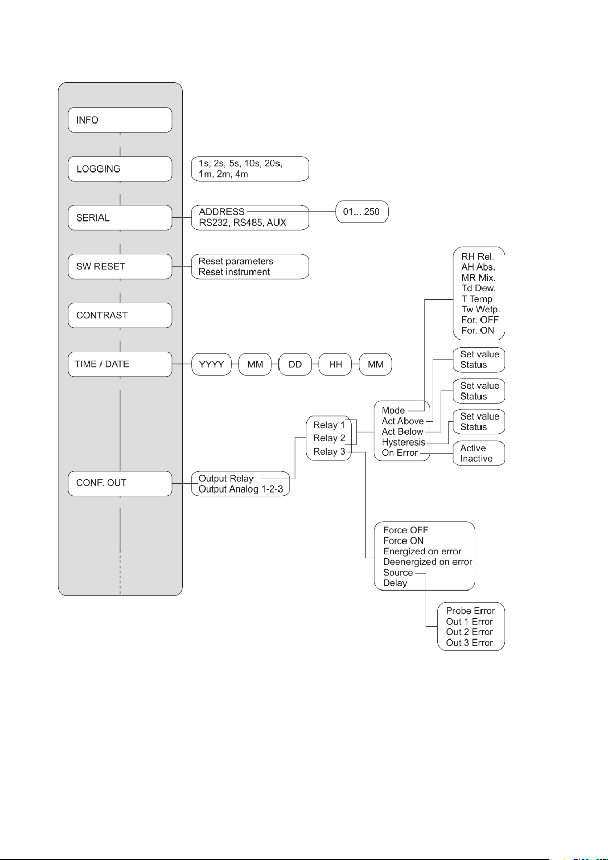
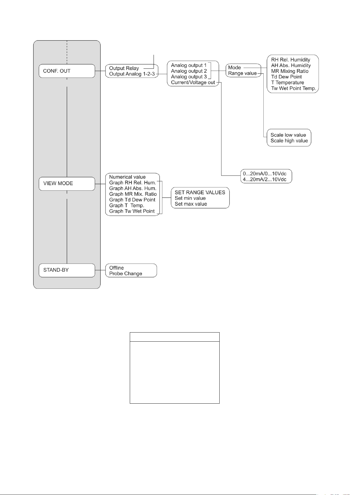
The following diagram describes the instrument menu structure.
MAIN MENU
Information
Logging
Serial communication
Program reset
LCD contrast
Time and date setting
Output configuration
Address
RS232, RS485, AUX COM port
Reset parameters
Reset instrument
Year Month Day Hours Minutes
Relative humidity
Absolute humidity
Mixing ratio
Dew point
Temperature
Wet bulb temperature
Always de-energised
Always energised
Set value
Status
Set value
Status
Set value
Status
Energised
De-energised
Mode
High threshold
Low threshold
Hysteresis
In case of error
Always de-energised
Always energised
Energised on error
De-energised on error
Source
Delay
Probe error
Analog output 1 error
Analog output 2 error
Analog output 3 error
Relay outputs
Analog outputs
Continues in the
next page
Continues in the next page
14
The menu items are listed in this order:
A. INFO
INFO
User ID=00000000000
Model HD28xxxTxxxxxxx
Smart transmitter
Firm.Ver.=xx.xx
Firm.Date=2008/01/31
Ser. Number=12345678
Probe Ser.=12345678
The INFO item provides information on version and firmware date, serial number and
calibration date, probe serial number, instrument alphanumeric ID.
The User ID is a code to identify the instrument and appears in the printouts and in the stored
data. It can be changed using the DeltaLog12 software. Press ESC to return to the menu basic
screen.
Continues from
previous page
Relay outputs
Analog outputs 1-2-3
Output configuration
View mode
Analog output 1
Analog output 2
Analog output 3
Type of output selection
Mode
Range limits
Relative humidity
Absolute humidity
Mixing ratio
Dew point
Temperature
Wet bulb temperature
Lower limit
Upper limit
Numerical value
Relative humidity graph
Absolute humidity graph
Mixing ratio graph
Dew point graph
Temperature graph
Wet bulb temperature graph
Set range
Set minimum level
Set maximum level
Off line mode
Change probe mode
Continues from previous page

15
B. LOGGING
LOGGING
LOG INTERVAL
select LOG interval
mm : ss
now set at: 00 : 01
<UP> <DOWN> change
<ESC> exit
The LOGGING item sets the interval in seconds and minutes between two loggings.
The available interval are: 1, 2, 5, 10, 20, 60 seconds, 2 and 4 minutes.
The set interval influences the graphic mode (please see the description of the “VIEW MODE”
item, later in this chapter).
Use the arrows to change the interval and press ENTER to confirm and return to the
menu main screen.
For the logging function details, please see the chapter “The logging function”.
C. SERIAL (Serial communication)
SERIAL
ADDRESS 001
* RS232
RS485
AUX
<UP> <DOWN> select
<ENTER> confirm
<ESC> exit
C.1. The first item “ADDRESS xxx” sets the instrument address so as to use it within a
network. The numbers from 001 (factory default) to 250 are available. The number 000
and the numbers 251 to 255 are reserved. To change the address, use the arrows
to select the “ADDRESS xxx” item and confirm with ENTER. The “ADDRESS xxx” message
will blink. Use the arrows to change its value and confirm with ENTER.
For the details, please see the paragraph “Serial communication and instrument
network”.
The other items select the serial communication port and the relevant protocol: use the
arrows to select one of the protocols and confirm with ENTER. An asterisk will appear near the
enabled item.
C.2. “RS232” enables the port at terminals 11 – 12 –13 and sets it as an RS232C port.
C.3. “RS485” enables the port at terminals 11 – 12 –13 and sets it as an RS485 port.
C.4. “AUX” enables the COM AUX auxiliary port as an RS232C serial port.
To use the first two ports, you need to shift the dip-switch located between the AUX COM
connector and terminal 11.

16
D. SW RESET (Program reset)
SW RESET
Reset parameters
Reset instrument
<UP> <DOWN> select
<ENTER> confirm
<ESC> exit
It is formed by two sub-functions:
D.1. “Reset parameters”: it performs a complete reset and restores the instrument to the
original factory conditions, restoring all menu parameters. The date and time are not
changed as they are managed by an independent circuit fitted with backup battery. The
memory data are not erased.
D.2. “Reset instrument”: it turns the instrument off and on. The menu parameters are not
changed. It work as disconnecting and reconnecting it to the mains.
Use the arrows to select the desired item and confirm with ENTER. When asked for
confirmation, use the arrows to select “YES” and confirm with ENTER.
E. CONTRAST
CONTRAST
Set contrast with
arrows
<UP> <DOWN> change
<ESC> exit
It adjusts the display contrast to suit different light conditions.
Use the arrows to change the contrast and press ENTER to confirm. The ESC key is used
to return to the menu main screen.
F. TIME / DATE (Time and date setting)
2008/01/31 12:00:00
TIME / DATE
year/mm/dd hh:mm
2008/01/31 12:00:00
<UP> <DOWN> change
<ENTER> confirm
<ESC> exit

17
The “TIME/DATE”item allows access to modify the instrument date and time. An internal
circuit fitted with backup battery ensures the correct functioning of the clock even in case of
mains power failure.
Date and time are expressed as year/month/day, hours/minutes/seconds.
Use the arrows to modify the year, already selected, and press ENTER to confirm.
You will get to the month setting. Change it using the arrows and confirm with
ENTER.
Repeat for the other items. The seconds start from 00 when pressing ENTER to confirm
the minutes.
After confirmation of the minutes you will exit the setting page and return to the menu
main screen.
G. CONF. OUT (Output configuration)
OUTPUT CONFIGURATION
Output Relay
Output Analog 1-2-3
<UP> <DOWN> select
<ENTER> confirm
<ESC> exit
The “Output configuration”item is composed of two sub-functions concerning the management
of relays (Output Relay) and analog outputs (Output Analog 1-2-3). The two following
paragraphs will outline in detail the relay and analog output settings: for a general description
on how to use of analog outputs and relays, please see the chapters “Instruments fitted with
relay outputs” and “Current and voltage analog outputs”.
G.1 Relay configuration
To set the three relays, select the CONF. OUT >> Output Relay menu item.
You will get to the screen with these three relays:
OUTPUT RELAY
Relay RL1
Relay RL2
Relay RL3
<UP> <DOWN> select
<ENTER> confirm
<ESC> exit/cancel
Use the arrows to select the relay to be configured and confirm with ENTER.

18
Relay RL1 (Working relay RL1)
It is used to set the functioning parameters of the RL1 working relay.
The following screen will appear:
RELAY RL1
Mode: T Temp.
Act Above: 100.0 °C
Act Below: 25.0 °C
Hysteresis: 1.0 °C
On Error: Inactive
<UP> <DOWN> select
<ESC> exit/cancel
Use the arrows to select the line to be modified and press ENTER to access the
corresponding submenu.
Mode It defines the physical quantity associated to the RL1 relay. To change the quantity,
use the arrows to select the line Mode and confirm with ENTER. The RELAY RL1
MODE menu will open.
RELAY RL1
MODE
For. OFF
T Temp.
*RH Rel.
Tw Wet bulb
AH Abs.
MR Mix.
Td Dew
For. ON
<ESC> exit/cancel
The current item is indicated by an asterisk (“RH Rel.” in the example): to change it,
use the arrows to select the new item and press ENTER. The asterisk will indicate
your new selection. Press ESC to return to the previous menu.
You can associate the following quantities to the RL1 relay:
•RH Rel. corresponds to relative humidity,
•AH Abs. corresponds to absolute humidity,
•MR Mix. corresponds to mixing ratio,
•Td Dew. corresponds to dew point,
•T Temp. corresponds to temperature,
•Tw Wetp. corresponds to the wet bulb temperature
•For. OFF (Force OFF) blocks the relay in the OFF state.
•For. ON (Force ON) blocks the relay in the ON state.
The last two items are useful during system maintenance and instrument
configuration.

19
Act above (high threshold) When the measurement increases, it represents the threshold (set
value) that shifts the relay from de-energised to energised when exceeded.
The contact to terminals 9 and 10 goes from closed to open. The contact to terminals
8 and 9 goes from open to closed.
The trigger threshold can be disabled, by setting the “status = inactive”.
RELE RL1
ACTIVE ABOVE
set value: 100.0°C
status: active
<UP> <DOWN> change
<ESC> exit/cancel
To change the threshold value, press ENTER to select the set value line and use the
arrows to set the desired value.
Press ENTER to go to the status line. Use the arrows to select active in order to
enable the trigger threshold, inactive to disable it.
Act below (low threshold) When the measurement decreases, it represents the threshold that
shifts the relay from de-energised to energised when exceeded.
The contact to terminals 9 and 10 goes from closed to open. The contact to terminals
8 and 9 goes from open to closed.
The trigger threshold can be disabled, by setting the “status = inactive”.
RELE RL1
ACTIVE BELOW
set value: 25.0°C
status: active
<UP> <DOWN> change
<ESC> exit/cancel
To change the trigger point value, press ENTER to select the set value line and use the
arrows to set the desired value.
Press ENTER to go to the status line. Use the arrows to select active in order to
enable the trigger threshold, inactive to disable it.
Hysteresis It represents the value of the relay RL1 hysteresis applied to both thresholds
defined above.
RELE RL1
HYSTERESIS
set value: 1.0°C
status: enable
<UP> <DOWN> change
<ESC> exit/cancel

20
To change the hysteresis width, press ENTER to select the set value line and use the
arrows to set the desired value.
Press ENTER to go to the status line. Use the arrows to select active in order to
enable the hysteresis, inactive to disable it.
On Error This parameter controls the relay RL1 behaviour if the physical quantity associated
to the relay goes in error.
The error occurs, e.g. when the measurement exceeds the functioning limits indicated
in the technical information, when the probe becomes faulty or gets disconnected.
This parameter can be set to “Active” or “Inactive”:
•If On_Error=Inactive (factory default), in case of error, the relay de-energises
independently of its current condition. The contact 9 –10 closes, the contact 8 –9
opens.
•If On_Error=Active, in case of error, the relay energises independently of its
current condition. The contact 9 –10 opens, the contact 8 –9 closes.
This parameter does not depend from other settings (upper or lower threshold,
hysteresis, ...) and neither from the relay’s state when the error occurs.
RELE RL1
ON ERROR
*Active
Inactive
<UP> <DOWN> select
<ESC> exit/cancel
The current mode is indicated by an asterisk (“Active” in the example): to change it,
use the arrows to select the new item and press ENTER. The asterisk will indicate
your new selection. Press ESC to return to the previous menu.
Relay RL2 (Working relay RL2)
It is used to set the functioning parameters of the RL2 working relay.
The following screen will appear:
RELAY RL2
Mode: RH Rel.
Act Above: 80.0 %
Act Below: 20.0 %
Hysteresis: 5.0 %
On Error: Inactive
<UP> <DOWN> select
<ESC> exit/cancel
Use the arrows to select the line to be modified and press ENTER to access the
corresponding submenu.
Mode It defines the physical quantity associated to the RL2 relay. To change the quantity,
use the arrows to select the line Mode and confirm with ENTER. The RELAY RL2
MODE menu will open.
This manual suits for next models
2
Table of contents
Other Delta OHM Transmitter manuals

Delta OHM
Delta OHM HD40.2 User manual

Delta OHM
Delta OHM HD45 17V User manual

Delta OHM
Delta OHM HD45 Series User manual

Delta OHM
Delta OHM HD402TR Series User manual

Delta OHM
Delta OHM HD9408.3B User manual

Delta OHM
Delta OHM DO 9861T User manual

Delta OHM
Delta OHM DO 9403T-R1 User manual

Delta OHM
Delta OHM PMsense User manual
Popular Transmitter manuals by other brands


Chiayo
Chiayo SM-2100 IrDA Operation manual

Becker
Becker Centronic SunWindControl SWC241 Assembly and operating instructions

Minebea Intec
Minebea Intec PR 5230 Instrument manual

MobileSpec
MobileSpec MBS13200 owner's guide

Siemens
Siemens sitrans lr 460 operating instructions

Vaisala
Vaisala WXT510 user guide


