Delta OHM HD402TR Series User manual

HD402T, HD402ST, HD402AT
24
• Sensor with high accuracy and stability
• Measurement of pressures relative to the atmosphere or dierential
pressures
• Dual analog output, current (active or passive) and voltage, or RS485
Modbus-RTU output
• Versions with or without LCD display
Applications
• Control of air conditioning and ventilation
• Control of lters
• Monitoring of clean rooms
• Pneumatic controls
• Respirators
• Vaporizers
Description
The series of transmitters HD402xT... is suitable for measuring relative
pressure with respect to atmosphere or dierential pressure in the range
from as low as 0-50 Pa to 0-200 kPa.
These transmitters use a silicon piezoresistive sensor with high accuracy
and temperature compensation, which has excellent linearity, repeatability
and stability over the time.
The output signal of the sensor is converted, depending on the model,
into a:
• RS485 Modbus–RTU digital output (HD402ST);
• voltage 0...10 V or active current 0...20 mA / 4...20 mA analog output
(HD402T);
• 2-wire (current loop) 4...20 mA analog output (HD402AT).
The output signal can be transmitted over long distances with high
immunity to interference (in the models with analog output the maximum
distance depends on the load and the section of the connection cables,
but distances of several hundred meters are commonly reached).
Dierent units of measurement can be chosen for each model and, in the
models with analog output, it is possible to choose the full scale (f.s.) value
for the output (high, intermediate or low range) and set the unipolar (0 ...
+f.s.) or bipolar (-f.s. ... +f.s.) measuring range.
The conguration can be made through a series of dip switches mounted
on the circuit board or by connecting the serial port of the transmitter to
the PC.
Thanks to the particular sensor used, the transmitters are insensitive to
orientation and position. Moreover, the high stability of the sensor over the
time and in comparison to the changes in temperature allows to eliminate
the operations of maintenance typically required to compensate for the
aging and the deviation of the sensor zero.
The option “display” (L) is available, in this case the values of pressure are
displayed on a 4 digit display under the unit of measure set by the user.
The transmitters are supplied ready for use and factory calibrated in 3
points.
Power supply: 24Vac or 18...40 Vdc for the models with voltage and active
current analog output, 12...30 Vdc for the models with passive current
analog output and for the models with RS485 Modbus RTU output.
Technical specications
Sensor Piezoresistive, High stability
Measuring range from 0…50 Pa to 0…200 kPa both relative and dierential
(please refer to table 1)
Resolution Please refer to table 2
Accuracy @ 25 °C
± 1.5% f.s. nominal for HD402xT1
± 0.75% f.s. nominal for HD402xT2
± 1% f.s. nominal for HD402xT3, HD402xT4 and HD402xT5
Accuracy @ 0…50 °C
± 3% f.s. nominal for HD402xT1
± 1% f.s. nominal for HD402xT2, HD402xT3, HD402xT4 and
HD402xT5
Long term stability
(1000 h) @ 25 °C
± 0.5% f.s. nominal for HD402xT1 and HD402xT2
± 0.35% f.s. nominal for HD402xT3
± 0.25% f.s. nominal for HD402xT4 and HD402xT5
Output
• HD402T…: Active analog 0…10 Vdc (RLmin = 10 k)) or
0…20 or 4…20 mA (RLmax = 500 )
• HD402AT…: 2-wire (current loop) 4…20 mA (RLmax =
(Vdc-12)/0,022)
• HD402ST…: Digital RS485 Modbus RTU
Response time Congurable 0.125, 1, 2 or 4 seconds for the output
0.5 seconds for the display updating
Overpressure limit
50 kPa for the models with f.s. up to 10 kPa
200 kPa for the model with f.s. 100 kPa
400 kPa for the model with f.s. 200 kPa
Compatible media Only air and non-aggressive dry gases
Power supply HD402T…: 24 Vac ± 10% or 18…40 Vdc
HD402AT, HD402ST…: 12…30 Vdc
Absorption HD402T… and HD402AT…: < 1 W @ 24 Vdc
HD402ST…: < 100 mW @ 12 Vdc
Pressure connection Ø 6.2 mm for tubes with internal Ø 5...6 mm
Electrical
connections
Screw terminal block, max 1.5 mm2 ,
PG9 cable gland for the input cable
Operating conditions -10...+60 °C / 0…95% RH
Storage temperature -20...+70 °C
Housing dimensions 80 x 84 x 44 mm
Protection degree IP65
HD402T HD402ST HD402AT
PRESSURE TRANSMITTERS

25
TAB. 1: full scale values and units of measurement
Model Pa kPa mbar mmH2O inchH2O mmHg PSI
HD402T1 50/100/250 --- 0,5/1/2,5 5/10/25 0,2/0,4/1 --- ---
HD402T2 250/500/1000 --- 2,5/5/10 25/50/100 1/2/4 --- ---
HD402T3 --- 2,5/5/10 25/50/100 --- --- 10/25/50 0,4/0,75/1,5
HD402T4 --- 25/50/100 250/500/1000 --- --- 100/250/500 4/7,5/15
HD402T5 --- 50/100/200 500/1000/2000 --- --- 250/500/1000 10/15/30
TAB. 2: resolution
Model Pa kPa mbar mmH2O inchH2O mmHg PSI
HD402T1 0.1 --- 0.001 0.01 0.001 --- ---
HD402T2 1--- 0.01 0.1 0.01 --- ---
HD402T3 --- 0.01 0.1 --- --- 0.01 0.001
HD402T4 --- 0.1 1 --- --- 0.1 0.01
HD402T5 --- 0.1 1 --- --- 1 0.01
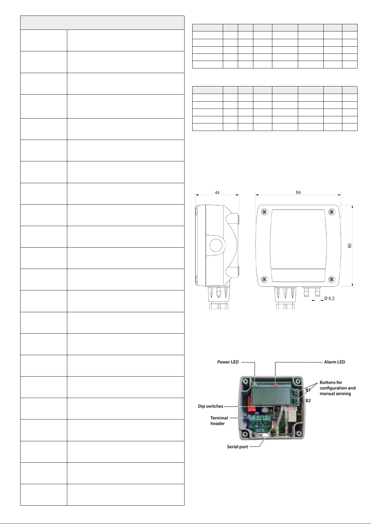
Fig. 1: dimensions (mm)
Installation
In any model the sensor and the electronics are housed in a rugged plastic
case with IP65 protection degree. By opening the lid, 3 mm diameter holes
are available so to allow securing the base of the transmitter directly to a
panel or to the wall.
65
50
Ø 3
Ø 3
Fig. 2: xing holes (dimensions in mm)
The transmitter can be mounted in any position, but typically it is secured
on a vertical wall with the pressure taps facedown. The deviation of the
zero due to the mounting position can be corrected by using CAL ZERO.
The procedure for the manual calibration of the zero is the following:
• make sure that the transmitter is powered at least for 1 hour;
• disconnect both the tubes from the pressure + and – inputs;
• press CAL ZERO until the red LED starts ashing;
• when the red LED turns o, the zeroing procedure is completed and
you can reconnect the tube to the pressure connections.
It is recommended to follow the auto-zero procedure at least once a year
under normal operating conditions.
CAL ZERO
LED
COM AUX
1 2 3 4 5 6
ON
DIP SWITCH
1 2 3 4 5 6
Models with active analog output
Models with RS485 output
Model with 2-wire current output
Fig. 3: CAL ZERO button and conguration dip-switches
26
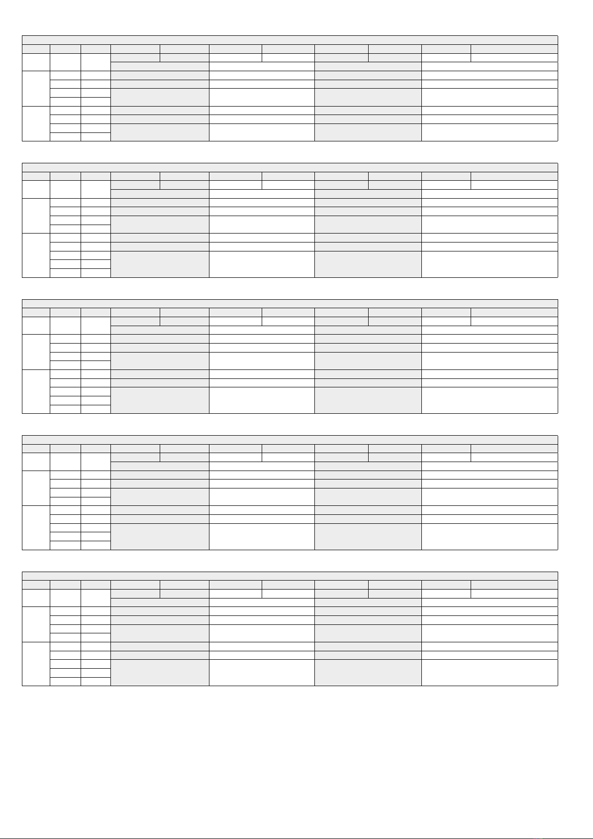
TAB. 3: measuring ranges for outputs of the models HD402T1 and HD402AT1
Dip switch number
6 2 3 4 5 4 5 4 5 4 5
OFF OFF ON OFF OFF ON ON ON
Pa mmH2O inchH2O mbar
OFF
OFF ON 0…50.0 Pa 0…5.00 mmH2O 0…0.200 inchH2O 0…0.500 mbar
ON OFF 0…100.0 Pa 0…10.00 mmH2O 0…0.400 inchH2O 0…1.000 mbar
OFF OFF 0…250.0 Pa 0…25.00 mmH2O 0…1.000 inchH2O 0…2.500 mbar
ON ON
ON
OFF ON -50.0…+50.0 Pa -5.00…+5.00 mmH2O -0.200…+0.200 inchH2O -0.500…+0.500 mbar
ON OFF -100.0…+100.0 Pa -10.00…+10.00 mmH2O -0.400…+0.400 inchH2O -1.000…+1.000 mbar
OFF OFF -250.0…+250.0 Pa -25.00…+25.00 mmH2O -1.000…+1.000 inchH2O -2.500…+2.500 mbar
ON ON
TAB. 4: measuring ranges for outputs of the models HD402T2 and HD402AT2
Dip switch number
6 2 3 4 5 4 5 4 5 4 5
OFF OFF ON OFF OFF ON ON ON
Pa mmH2O inchH2O mbar
OFF
OFF ON 0…250 Pa 0…25.0 mmH2O 0…1.00 inchH2O 0…2.50 mbar
ON OFF 0…500 Pa 0…50.0 mmH2O 0…2.00 inchH2O 0…5.00 mbar
OFF OFF 0…1000 Pa 0…100.0 mmH2O 0…4.00 inchH2O 0…10.00 mbar
ON ON
ON
OFF ON -250…+250 Pa -25.0…+25.0 mmH2O -1.00…+1.00 inchH2O -2.50…+2.50 mbar
ON OFF -500…+500 Pa -50.0…+50.0 mmH2O -2.00…+2.00 inchH2O -5.00…+5.00 mbar
OFF OFF
-1000…+1000 Pa -100.0…+100.0 mmH2O -4.00…+4.00 inchH2O -10.00…+10.00 mbarON ON
ON ON
TAB. 5: measuring ranges for outputs of the models HD402T3 and HD402AT3
Dip switch number
6 2 3 4 5 4 5 4 5 4 5
OFF OFF ON OFF OFF ON ON ON
kPa mmHg PSI mbar
OFF
OFF ON 0…2.50 kPa 0…10.00 mmHg 0…0.400 PSI 0…25.0 mbar
ON OFF 0…5.00 kPa 0…25.00 mmHg 0…0.750 PSI 0…50.0 mbar
OFF OFF 0…10.00 kPa 0…50.00 mmHg 0…1.500 PSI 0…100.0 mbar
ON ON
ON
OFF ON -2.50…+2.50 kPa -10.00…+10.00 mmHg -0.400…+0.400 PSI -25.0…+25.0 mbar
ON OFF -5.00…+5.00 kPa -25.00…+25.00 mmHg -0.750…+0.750 PSI -50.0…+50.0 mbar
OFF OFF
-10.00…+10.00 kPa -50.00…+50.00 mmHg -1.500…+1.500 PSI -100.0…+100.0 mbarON ON
ON ON
TAB. 6: measuring ranges for outputs of the models HD402T4 and HD402AT4
Dip switch number
6 2 3 4 5 4 5 4 5 4 5
OFF OFF ON OFF OFF ON ON ON
kPa mmHg PSI mbar
OFF
OFF ON 0…25.0 kPa 0…100.0 mmHg 0…4.00 PSI 0…250 mbar
ON OFF 0…50.0 kPa 0…250.0 mmHg 0…7.50 PSI 0…500 mbar
OFF OFF 0…100.0 kPa 0…500.0 mmHg 0…15.00 PSI 0…1000 mbar
ON ON
ON
OFF ON -25.0…+25.0 kPa -100.0…+100.0 mmHg -4.00…+4.00 PSI -250…+250 mbar
ON OFF -50.0…+50.0 kPa -250.0…+250.0 mmHg -7.50…+7.50 PSI -500…+500 mbar
OFF OFF
-100.0…+100.0 kPa -500.0…+500.0 mmHg -15.00…+15.00 PSI -1000…+1000 mbarON ON
ON ON
TAB. 7: measuring ranges for outputs of the models HD402T5 and HD402AT5
Dip switch number
6 2 3 4 5 4 5 4 5 4 5
OFF OFF ON OFF OFF ON ON ON
kPa mmHg PSI mbar
OFF
OFF ON 0…50.0 kPa 0…250 mmHg 0…10.00 PSI 0…500 mbar
ON OFF 0…100.0 kPa 0…500 mmHg 0…15.00 PSI 0…1000 mbar
OFF OFF 0…200.0 kPa 0…1000 mmHg 0…30.00 PSI 0…2000 mbar
ON ON
ON
OFF ON -50.0…+50.0 kPa -250…+250 mmHg -10.00…+10.00 PSI -500…+500 mbar
ON OFF -100.0…+100.0 kPa -500…+500 mmHg -15.00…+15.00 PSI -1000…+1000 mbar
OFF OFF
-200.0…+200.0 kPa -1000…+1000 mmHg -30.00…+30.00 PSI -2000…+2000 mbarON ON
ON ON
27
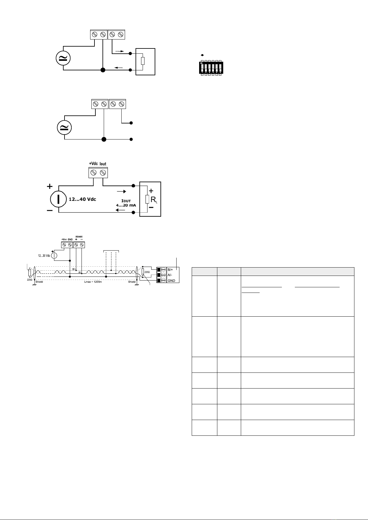
Electrical connections
Fig. 4: active current analog output
Fig. 5: voltage analog output
Fig. 6: 2-wire current analog output
Fig. 7: RS485 connection
In the RS485 connection, the instruments are connected in a sequence
through a shielded cable with twisted pair for signals and a third wire for the
common. Line termination must be set at the two network ends.
The maximum number of devices that can be connected to the RS485 line
(Bus) depends on the load characteristics of the devices to be connected. The
RS485 standard requires that the total load does not exceed 32 unit loads. The
load of an HD402ST… transmitter is equal to ¼ of unit load. If the total load is
greater than 32 unit loads, divide the network into segments and add a signal
repeater between a segment and the successive one. Line termination should
be applied at both ends of each segment.
The instrument has a built in line termination that can be connected or removed
through a short jumper placed next to the terminal block. If the instrument is
the last or the rst device of a network group, connect the termination placing
the short jumper between the“RT”and“120 ohm”indications. If the instrument
is not at the end of a network group, remove the termination placing the short
jumper between the “RT”and“OPEN”indications.
The cable shield must be connected to both line ends. The cable should have
the following features:
• Characteristic impedance: 120 ohm
• Capacity: less than 50pF/m
• Resistance: less than 100 ohm/km
• Gauge: 0,22 mm (AWG24) at least
The cable maximum length depends on baud rate and cable characteristics.
Typically, the maximum length is 1200 m.The data line must be kept separated
from any power lines in order to prevent interferences on the transmitted
signal.
+Vcc
+Vcc
Iout
Iout
Vout
Current
output
Voltage
output
Vout
GND
GND
24 Vac
18...40 Vdc
24 Vac
18...40 Vdc
+
+
-
-
I
0/4...20 mA
OUT
+
-
RL
+
-
V
0...10 V
OUT
Powe supply
Termination
Termination
Other sensors with
RS485 output
PLC, data logger or
RS485/USB or RS485/
RS232 converter for PC
CONFIGURATION OF THE MODELS WITH ANALOG OUTPUT (HD402T... /
HD402AT…)
Setting the conguration mode: the transmitter can be congured by using
the dip switches on the circuit board or via the serial communication port COM
AUX. The choice of the conguration mode is done with the dip switch 1:
1 2 3 4 5 6
ON
1 2 3 4 5 6
ON
OFF
Dip switch 1 = ON →the conguration set through the
dip switches 2...6 is used
Dip switch 1 = OFF →the conguration set via serial port
is used
Conguration by dip switch (models with analog output)
The conguration of the dip switches is used by the transmitter only if the
dip switch 1 is ON.
The dip switches 2 and 3 select the low, intermediate or high measuring
range for the analog output.
The dip switches 4 and 5 select one of the four available units in the model.
The dip switch 6 sets the unipolar (0 ... + f.s.) or bipolar (-f.s.....+ f.s.) measuring
range for the analog output.
A dip switch is OFF when placed down, towards the serial connector. Instead,
it is ON if placed up, towards the DIP SW sign.
The tables 3 to 7 at the following pages report..... report the measuring range,
for each model, corresponding to the analog outputs according to dip switch
positions.
Conguration via the serial port COM AUX (models with analog output)
The conguration set with the serial communication is used by the
transmitter only if the dip switch 1 is OFF.
In order to modify the settings, please proceed as follows:
• Connect the serial COM AUX output of the transmitter to the RS232
port (via the RS27 cable) or USB (via the cable CP27) of the PC. If you
use the CP27 cable, install the USB drivers on your PC.
• On the PC, launch a program for serial communication (e.g.
Hyperterminal), set the baud rate to 115200 and the communication
parameters to 8N1.
• Send the commands given in table 8 to set the measurement range
corresponding to the analog outputs.
TAB. 8: conguration serial commands (models with analog output)
Command Response Description
Kn &
Set the unit of measurement of index n
HD402T1 & HD402T2 HD402T3 & HD402T4 &
HD402T5
n=0 →Pa n=0 →kPa
n=1→mmH2O n=1 → mmHg
n=2 →inchH2O n=2 →PSI
n=3 →mbar n=3 →mbar
Rn &
Set the measuring range of index n
n=0 →high range (e.g. 250 Pa / 25 mmH2O / 1“H2O /
2,5 mbar in HD402T1)
n=1 →intermediate range (e.g. 100 Pa / 10 mmH2O / 0,4“H2O
/ 1 mbar in HD402T1)
n=2 →low range (e.g. 50 Pa / 5 mmH2O / 0,2“H2O /
0,5 mbar in HD402T1)
PU & Set the unipolar measuring range (0…+f.s.)
PB & Set the bipolar measuring range (-f.s.…+f.s.)
Sn & Set the response time of index n for the analog outputs
n=0 ⇒0.125 s n=1 ⇒1 s n=2 ⇒2 s n=4 ⇒4 s
U0 & Set the interval 0…20 mA for the analog active current
output
U1 & Set the interval 4…20 mA for the analog active current
output
In order to read the settings of the transmitter, send the commands
described in Table 9.
+Vcc
+Vcc
Iout
Iout
Vout
Uscita in
corrente
Uscita in
tensione
Vout
GND
GND
24 Vac
16...40 Vdc
24 Vac
16...40 Vdc
+
+
-
-
I
0/4...20 mA
OUT
+
-
RL
+
-
V
0...10 V
OUT

28
TAB. 9: serial commands to read the conguration (models with analog
output)
Command Response Description
G0
See the
example
below
It reads the current conguration of the transmitter.
If the dip switch 1 is OFF, it returns the conguration
set via the serial port. If the dip switch 1 is set to ON, it
returns the conguration set by dip switch
GF
See the
example
below
It reads the conguration set by the serial port
GS
See the
example
below
It reads the conguration set by the dip switch
S? Response
time It reads the response time set for the analog outputs
The commands G0, GF and GS for reading the conguration return a string
consisting of:
• model
• full scale value set for the analog outputs
• polarity of the measuring range (U=unipolar, B=bipolar)
• range of the analog output current (0=0...20mA, 4=4...20 mA)
for example: the string“HD402T2 5.00mbar B40”indicates that the transmitter
model is HD402T2, the full scale set for the analog outputs is 5.00 mbar,
the measuring range is bipolar (-5.00…+5.00 mbar) and the analog current
output type is 4...20 mA. The last character of the string (0 in the example) is a
condential code.
CONFIGURATION OF THE MODELS WITH RS485 MODBUS-RTU OUTPUT
(HD402ST...)
RS485 Modbus address: each transmitter of the network is univocally identied
by an address between 1 and 247. Transmitters having the same address shall
not be present in the network. The transmitter Modbus address is equal to the
sum of the value set with the dip switches 2…6 (value settable from 0 to 31)
and the value set with the serial command WA (value settable from 1 to 216,
default = 1). By setting a dip-switch to ON (upwards), the following values are
added to the address:
Dip-switch
2
Dip-switch
3
Dip-switch
4
Dip-switch
5
Dip-switch
6
ON 16 8 4 2 1
OFF 00000
Example: if the dip-switches 2 and 4 are set to ON, and the dip-switches 3,5
and 6 are set to OFF, the value set with the dip-switches is 16+4=20. If the value
set with the serial command WA is 1 (default value), the transmitter Modbus
address is 20+1=21.
The dip-switches can be set even if the transmitter is powered, and the change
is eective immediately.
Conguration via the RS485 serial port (models HD402ST…)
The transmitters are preset by the factory. To change the settings, proceed as
follows:
• Connect the transmitter RS485 output to the PC RS232 (through a RS485/
RS232 converter) or USB (through a RS485/USB converter, for example the
RS48 cable) port. If a RS485/USB converter is used, install in the PC the
related USB drivers.
• To enable the conguration mode, set the dip-switch 1 (the one closest to
the terminal block) to ON (upwards), then power the transmitter.
Note: the dip-switch 1 can be changed from OFF to ON even when the
instrument is powered; in this case it is however necessary, after setting
the dip-switch to ON, to press briey (less than 0.5 seconds) the CAL
ZERO button to enable the conguration mode (the transmitter model
information appears on display, if present). Alternatively, power cycle the
transmitter.
• In the PC, run a serial communication software (e.g. Hyperterminal), set the
baud rate to 57600 and the communication parameters to 8N1.
• Send the CAL START command (the command is required to change the
conguratrion; to read the value of the parameters, the command is not
required).
• Send the commands given in table 10 to set or read the conguration
parameters of the transmitter.
TAB. 10: serial commands (models with RS485 Modbus RTU
output)
Command Description
Response time
AVGn
Set the response time of index n for the
measurement
n=0 ⇒0.125 s, n=1 ⇒1 s, n=2 ⇒2 s, n=4 ⇒4 s
AVG? Reads the response time set for the
measurement
Unit of measurement
DU0
Shows pressure in Pa (HD402ST1 and HD402ST2)
or kPa (HD402ST3, HD402ST4 and HD402ST5) on
display
DU1
Shows pressure in mmHO (HD402ST1 and
HD402ST2) or mmHg (HD402ST3, HD402ST4 and
HD402ST5) on display
DU2
Shows pressure in inchHO (HD402ST1 and
HD402ST2) or PSI (HD402ST3, HD402ST4 and
HD402ST5) on display
DU3 Shows pressure in mbar on display
Modbus parameters
WA n...n
Sets the Modbus base address to the value n…n
The value must be between 1 and 216
(default = 1)
Warning: the actual Modbus address of the
transmitter is equal to the base address set
with this command plus the value set with the
dip-switches.
Note: in the reply to the command, the previous
actual address appears; the new address will
appear in the replies to the next commands.
BAUD r...r
Sets the Modbus Baud Rate to the value r…r
The acceptable values are 9600 and 19200
(default = 19200) If the command is sent
without the parameter r…r, the current setting
is obtained
PAR p
Sets the Modbus communication parameters of
index p
p=O ⇒8O1 p=N ⇒8N2 p=E ⇒8E1
If the command is sent without the index p, the
current setting is obtained (default = 8E1).
Note: the replies of the transmitters with RS485 Modbus RTU output always
start with the address of the connected transmitter. For example, sending
the AVG2 command to a transmitter with Modbus address 1, the reply is “001:
averaging = 2 sec”.
To exit the conguration mode after sending the CAL START command, send
the CAL END command (the transmitter automatically exits the conguration
mode after 5 minutes from the last command sent).
MODBUS-RTU MODE
To operate with the Modbus-RTU protocol be sure that the dip-switch 1 (the
one closest to the terminal block) is set to OFF (downwards). The dip-switch
can be set to OFF even if the transmitter is powered, and the change is eective
immediately.
The measured values can be read in Modbus RTU mode by using the 04h
function code (Read Input Registers). Table 11 lists the Modbus Input Registers
available:

29
TAB. 11: MODBUS Input Registers
Register
number
Register
address Datum Format
4 3 Pressure in tenths of Pa (only
HD402ST1) 16-bit
integer
5 4 Pressure in Pa (only HD402ST1,
HD402ST2 and HD402ST3) 16-bit
integer
6 5 Pressure in daPa (only HD402ST2,
HD402ST3 and HD402ST4) 16-bit
integer
7 6 Pressure in hPa (only HD402ST3,
HD402ST4 and HD402ST5) 16-bit
integer
8 7 Pressure in kPa (only HD402ST4
and HD402ST5) 16-bit
integer
9 8 Pressure in hundredths of
mmHO (only HD402ST1 and
HD402ST2)
16-bit
integer
10 9 Pressure in tenths of mmHO
(only HD402ST1, HD402ST2 and
HD402ST3)
16-bit
integer
11 10 Pressure in mmHO (only
HD402ST2, HD402ST3 and
HD402ST4)
16-bit
integer
12 11 Pressure in thousandths of
inchHO (only HD402ST1 and
HD402ST2)
16-bit
integer
13 12 Pressure in hundredths of
inchHO (only HD402ST2 and
HD402ST3)
16-bit
integer
14 13 Pressure in tenths of inchHO
(only HD402ST3, HD402ST4 and
HD402ST5)
16-bit
integer
15 14 Pressure in inchHO (only
HD402ST4 and HD402ST5) 16-bit
integer
16 15 Pressure in thousandths of
mmHg (only HD402ST2) 16-bit
integer
17 16 Pressure in hundredths of mmHg
(only HD402ST2 and HD402ST3) 16-bit
integer
18 17 Pressure in tenths of mmHg (only
HD402ST3 and HD402ST4) 16-bit
integer
19 18 Pressure in mmHg (only
HD402ST4 and HD402ST5) 16-bit
integer
20 19 Pressure in thousandths of PSI
(only HD402ST3) 16-bit
integer
21 20 Pressure in hundredths of PSI
(only HD402ST3, HD402ST4 and
HD402ST5)
16-bit
integer
27 26 Error register. 16-bit
integer
Reading a register not available for a particular model returns the value -32768
(0x8000).
Error register
The bits of the error register signal, if set to 1, anomalies in the measurement.
The bit 0 (the less signicant one) indicates a measurement over-range of
the transmitter. The bit 1 indicates whether the measurement is less than the
minimum measurable (under-range). The bits 2 and 3 indicate sensor errors.
TAB. 12: MODBUS - Holding Registers
Register
number
Register
address Datum Format
101 100
Modbus base address
(from 1 to 216)
Warning: the actual Modbus
address of the transmitter is
equal to the base address set in
this register plus the value set
with the dip-switches.
16-bit
integer
102 101
Modbus Baud Rate
Acceptable values: 3 (⇒9600)
and 4 (⇒19200)
16-bit
integer
103 102
Modbus communication para-
meters
Acceptable values: 1 (⇒8N2), 2
(⇒8E1) and 4 (⇒8O1)
16-bit
integer
The Modbus Holding Registers allow setting the same Modbus parameters
that can be set via the serial commands WA, BAUD and PAR. Use the 06h
(Write Single Register) and 03h (Read Holding Registers) function codes to
write and read respectively the content of the registers.
To make the changes of the Holding Registers content active and
permanent, write the hexadecimal value FF00 in the Coil Register number
3 (address 2) by using the 05h function code (Write Single Coil).
TAB. 13: MODBUS - Coils
Register
number
Register
address Datum
3 2 Activation and permanent storage of the Hol-
ding Registers content changes.
Display
Models withsuxLare equippedwith a 4-digit LCD display. In modelswith LCD
option, the measuring range shown on the display is always bipolar (-f.s.....+f.s.)
and related to the maximum full scale available in the model (the setting of the
measuring range only aects the behavior of the analog outputs).
The measure on the display is updated twice a second.
Error messages:
Undr → it appears if the measured value is less than the minimum
measurable value
OvEr → it appears if the measured value exceeds the maximum mea-
surable value
CAL Error→ it appears at the end of the zero calibration if the maximum
oset value possible to be corrected is exceeded.
ORDERING CODES
HD402T…: Pressure relative to the atmosphere or dierential pressure
transmitters. For dry air and non-aggressive gases. Barbed connection.
Ø 6.2 mm for tubes with internal Ø 5...6 mm pressure inputs. RS485
Modbus RTU output (HD402ST), voltage 0...10 V or active current 0...20
mA / 4...20 mA analog output (HD402T) or 2-wire (current loop) 4...20
mA analog output (HD402AT). Operating temperature 10...+60 °C.
Power supply: 24Vac or 18...40 Vdc for the models with voltage and
active current analog output, 12...30 Vdc for the models with passive
current analog output and for the models with RS485 Modbus RTU
output.
HD402 T - L
L= with LCD display
Nominal full scale (f.s.):
1= 250 Pa / 25 mmHO / 1 inchHO / 2,5 mbar
2= 1000 Pa / 100 mmHO / 4 inchHO / 10 mbar
3= 10 kPa / 50 mmHg / 1,5 PSI / 100 mbar
4= 100 kPa / 500 mmHg / 15 PSI / 1000 mbar
5= 200 kPa / 1000 mmHg / 30 PSI / 2000 mbar
Output:
Blank = voltage and active current analog output
A= 2-wire (current loop) 4…20 mA output
S= RS485 Modbus-RTU output

HD402TR...SERIES
• Sensor with high accuracy and stability
• Measurement of pressures relative to the atmosphere or dierential
pressures
• Relay switch output
• Front alarm LED and audible alarm
• Settable thresholds, hysteresis and delay
• Auto-zeroing feature in the low range model
• LCD display and 2 conguration keys
30
Accessories
Included:
•N°1 piece of silicone tubing Ø 5 int./ Ø 8 ext. length 2 m
•N°2 plastic ttings HD434T.5
Upon request:
AP3719: Air inlet for square or cylindrical channel.
AP3721: Air inlet for cylindrical channel, made of plastic.
RS27: RS232 null-modem serial connection cable with 9 poles sub-D 9
female and 3-pole connectors for COM AUX port.
CP27: Serial connection cable with USB connector for PC and 3-pole
connector for COM AUX port. The cable has a built-in USB/RS232
converter and connects the instrument directly to the USB port of the
PC.
Fig. 8: AP3719
duct probe
135
13 31
Ø 4.5
88
69
6
H
FLOW
L
Fig. 9: AP3721 duct probe
EXAMPLE OF CONNECTION WITH THE INDICATOR CONTROLLER HD9022
CAL ZERO
LED
COM AUX
1 2 3 4 5 6
ON
DIP SWITCH
1 2 3 4 5 6
Iin
GND
ALARM HI
LO
HD9022
18...40 Vdc
24 Vac
Power supply
+
Fig. 10: active current output 0…20 or 4…20 mA
CAL ZERO
LED
COM AUX
1 2 3 4 5 6
ON
DIP SWITCH
1 2 3 4 5 6
Vin
GND
ALARM HI
LO
HD9022
24 Vac
Power supply
18...40 Vdc
+
Fig. 11: voltage output 0…10 Vdc
Fig. 12: 2-wire (current loop) 4…20 mA output
HD402TR…L series
Pressure ON/OFF relay switches
The series of pressure ON/OFF relay switches HD402TR...L is suitable for
controlling the relative pressure with respect to atmosphere or dierential
pressure in the range from ±250 Pa to ±200 kPa.
If the set threshold value is exceeded, the relay switch output is activated,
the front alarm LED lights up and an audible alarm sounds. The alarm can
be congured to be activated when the measurement becomes higher
or lower than the set threshold. 1 or 2-threshold operating modes are
available.
A silicon piezoresistive sensor with high accuracy and temperature
compensation is used, which allows excellent linearity, repeatability and
stability over the time.
The auto-zeroing feature in the low range model (HD402TR1L) allows
stable measurements over the time without the need to recalibrate.
The instruments are equipped with a 4-digit LCD display and dierent units
of measurement can be chosen for each model.
The conguration can be made through the dip switches mounted on the
circuit board (only for the unit of measurement), via the internal buttons or
by connecting the serial port of the instrument to the PC.
Thanks to the particular sensor used, the instruments are insensitive to
orientation and position. Moreover, the high stability of the sensor over the
time and in comparison to the changes in temperature allows eliminating
the operations of maintenance typically required to compensate for the
aging and the deviation of the sensor zero.
The instruments are supplied ready for use and factory calibrated.
Power supply: 24Vac or 15...36 Vdc.
137
43
Ø 60
Ø42 N° 3x120°
Ø5,5
3
6
31
Technical specications
Sensor Piezoresistive, High stability
Measuring range from 0…50 Pa to 0…200 kPa both relative and dierential
(please refer to table 1)
Resolution Please refer to table 2
Accuracy @ 25 °C
± 1.5% f.s. nominal for HD402TR1L
± 0.75% f.s. nominal for HD402TR2L
± 1% f.s. nominal for HD402TR3L, HD402TR4L and
HD402TR5L
Accuracy @ 0…50 °C
± 3% f.s. nominal for HD402TR1L
± 1% f.s. nominal for HD402TR2L, HD402TR3L, HD402TR4L
and HD402TR5L
Long term stability
(1000 h) @ 25 °C
± 0.5% f.s. nominal for HD402TR1L and HD402TR2L
± 0.35% f.s. nominal for HD402TR3L
± 0.25% f.s. nominal for HD402TR4L and HD402TR5L
Alarm Front LED, internal buzzer, relay switch
Output
SPDT Relay switch
3 A/250 Vac
3 A/30 Vdc resistive load
Connection to pc RS232 serial port Can be connect to a USB port by using
the optional CP27 adapter
Conguration Settable unit of measurement, thresholds, hysteresis, delay
and alarm operation mode
Auto-zero Automatic for HD402TR1L, manual for the other models
Response time 0.5 seconds for the display updating
Overpressure limit
50 kPa for HD402TR1L, HD402TR2L and HD402TR3L
200 kPa for HD402TR4L
400 kPa for HD402TR5L
Compatible media Only air and non-aggressive dry gases
Power supply 24 Vac ± 10% or 15…36 Vdc
Absorption < 1 W @ 24 Vdc
Pressure connection Ø 6.2 mm for tubes with internal Ø 5...6 mm
Electrical
connections
Screw terminal block, max 1.5 mm2 , PG9 cable gland for
the input cable
Operating conditions -10...+60 °C / 0…95% RH
Storage temperature -20...+70 °C
Housing dimensions 80 x 84 x 44 mm
Protection degree IP65
Model Pa kPa mbar mmHO inchHO mmHg PSI
HD402TR1L 250 --- 2.5 25 1--- ---
HD402TR2L 1000 --- 10 100 4--- ---
HD402TR3L --- 10 100 --- --- 50 1.5
HD402TR4L --- 100 1000 --- --- 500 15
HD402TR5L --- 200 2000 --- --- 1000 30
Model Pa kPa mbar mmHO inchHO mmHg PSI
HD402TR1L 0.1 --- 0.001 0.01 0.001 --- ---
HD402TR2L 1--- 0.01 0.1 0.01 --- ---
HD402TR3L --- 0.01 0.1 --- --- 0.01 0.001
HD402TR4L --- 0.1 1 --- --- 0.1 0.01
HD402TR5L --- 0.1 1 --- --- 1 0.01
TAB. 1: full scale values and units of measurement
TAB. 2: resolution
Dimensions
Internal view

32
ORDERING CODES
HD402TR…L Relative or dierential pressure controller with ON/
OFF relay switch. Range from ±250 Pa to ±200 kPa depending on
model. 4-digit LCD display. User congurable via serial port or internal
buttons. Operating temperature 10...+60 °C. Suitable for measuring
non-corrosive gases or dry air. Ø 6.2 mm for tubes with internal Ø 5...6
mm pressure inputs. Power supply 24 Vac or 15...36 Vdc.
HD402TR L
Range:
1= ± 250 Pa / 25 mmHO / 1 inchHO / 2,5 mbar
2= ± 1000 Pa / 100 mmHO / 4 inchHO / 10 mbar
3= ± 10 kPa / 50 mmHg / 1,5 PSI / 100 mbar
4= ± 100 kPa / 500 mmHg / 15 PSI / 1000 mbar
5= ± 200 kPa / 1000 mmHg / 30 PSI / 2000 mbar
137
43
Ø 60
Ø42 N° 3x120°
Ø5,5
3
6
135
13 31
Ø 4.5
88
69
6
H
FLOW
L
AP3719 Flow port for for square or cylindrical duct.
AP3721 Plastic ow port for cylindrical duct.
RS27 RS232 null-modem serial connection cable with SubD 9-pin
connector on the PC side and 3-pole connector on the instrument side.
CP27 Connection cable with built-in USB/RS232 converter. USB con-
nector on the PC side and 3-pole connector on the instrument side.
ELECTRICAL CONNECTIONS
CONFIGURATION
The conguration of the instruments can be done via serial commands by
connecting the instrument serial port to a PC and using a standard serial
communication program, or by using the two internal conguration buttons.
Below are the operating parameters that can be congured:
• Relay operating mode:
Negative: NC contact is closed if no alarm, NO contact is closed if in alarm.
Positive: NO contact is closed if no alarm, NC contact is closed if in alarm.
• Buzzer activation: ON (buzzer enabled) or OFF (buzzer disabled).
• Alarm activation: ON (alarm enabled) or OFF (alarm disabled).
• Alarm operating mode:
Above threshold: alarm is on if measurement is greater than the set
threshold.
Below threshold: alarm is on if measurement is less than the set threshold.
Outside thresholds: alarm is on if measurement is less than lower threshold
or greater than upper threshold.
• Threshold 1: Value of the threshold for above and below alarm operating
modes; value of the lower threshold for outside thresholds alarm operating
mode.
• Threshold 2: Value of the upper threshold for outside thresholds alarm
operating mode.
• Hysteresis: Value of the hysteresis for above and below threshold alarm
operating modes.
• Alarm activation delay: Value in seconds of the time delay for generating
the alarm. The alarm is generated only if the measurement exceeds the
threshold for more than the set time.
• Alarm deactivation delay: Value in seconds of the time delay for
deactivating the alarm. The alarm is deactivated only after the set time has
elapsed from the disappearance of the alarm condition.
This manual suits for next models
14
Table of contents
Other Delta OHM Transmitter manuals

Delta OHM
Delta OHM HD9408.3B User manual

Delta OHM
Delta OHM DO 9403T-R1 User manual

Delta OHM
Delta OHM HD45 17V User manual

Delta OHM
Delta OHM HD45 Series User manual

Delta OHM
Delta OHM HD40.2 User manual

Delta OHM
Delta OHM HD2817T Series User manual

Delta OHM
Delta OHM DO 9861T User manual

Delta OHM
Delta OHM PMsense User manual


