Delta OHM HD40.2 User manual
Operating manual
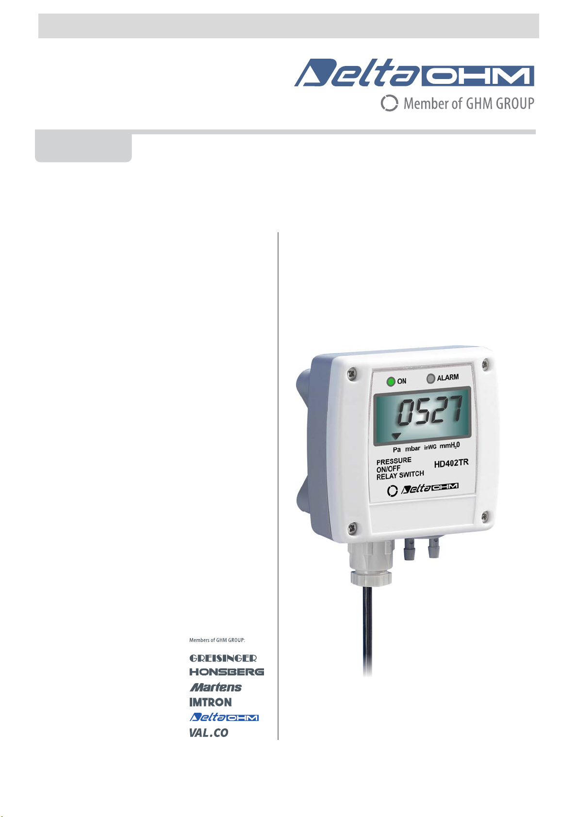
Pressure ON/OFF relay switches
HD402TR…L series
www.deltaohm.com
English
Keep for future reference.
Companies / Brands of GHM

HD402TR - 2 - V1.0
TABLE OF CONTENTS
1INTRODUCTION....................................................................................................3
2TECHNICAL CHARACTERISTICS ............................................................................4
3INSTALLATION .....................................................................................................6
3.1ELECTRICAL CONNECTIONS ..................................................................................... 7
3.2CONFIGURATION ................................................................................................. 7
4ALARM OPERATING MODES ................................................................................11
5INSTRUMENT STORAGE ......................................................................................13
6SAFETY INSTRUCTIONS......................................................................................13
7ORDERING CODES .............................................................................................. 14

HD402TR - 3 - V1.0
1INTRODUCTION
The series of pressure ON/OFF relay switches HD402TR...L is suitable for controlling
the relative pressure with respect to atmosphere or differential pressure in the range
from ±250 Pa to ±200 kPa.
If the set threshold value is exceeded, the relay switch output is activated, the front
alarm LED lights up and an audible alarm sounds. The alarm can be configured to be
activated when the measurement becomes higher or lower than the set threshold. 1
or 2-threshold operating modes are available.
A silicon piezoresistive sensor with high accuracy and temperature compensation is
used, which allows excellent linearity, repeatability and stability over the time.
The auto-zeroing feature in the low range model (HD402TR1L) allows stable mea-
surements over the time without the need to recalibrate.
The instruments are equipped with a 4-digit LCD display and different units of mea-
surement can be chosen for each model.
The configuration can be made through the dip switches mounted on the circuit board
(only for the unit of measurement), via the internal buttons or by connecting the seri-
al port of the instrument to the PC.
Thanks to the particular sensor used, the instruments are insensitive to orientation
and position. Moreover, the high stability of the sensor over the time and in compari-
son to the changes in temperature allows eliminating the operations of maintenance
typically required to compensate for the aging and the deviation of the sensor zero.
The instruments are supplied ready for use and factory calibrated.
Power supply: 24Vac or 15...36 Vdc.
HD402TR - 4 - V1.0
2TECHNICAL CHARACTERISTICS
Sensor Piezoresistive, High stability
Measuring range From ±250 Pa to ±200 kPa both relative and differential
Refer to table 1
Resolution Refer to table 2
Accuracy @ 25 °C ± 1.5% f.s. nominal for HD402TR1L
± 0.75% f.s. nominal for HD402TR2L
± 1% f.s. nominal for HD402TR3L, HD402TR4L and HD402TR5L
Accuracy @ 0…50 °C ± 3% f.s. nominal for HD402TR1L
± 1% f.s. nominal for HD402TR2L, HD402TR3L, HD402TR4L and
HD402TR5L
Long term stability (1000 h)
@ 25 °C ± 0.5% f.s. nominal for HD402TR1L and HD402TR2L
± 0.35% f.s. nominal for HD402TR3L
± 0.25% f.s. nominal for HD402TR4L and HD402TR5L
Alarm Front LED, internal buzzer, relay switch
Output SPDT Relay switch
3 A/250 Vac
3 A/30 Vdc resistive load
Connection to PC RS232 serial port
Can be connect to a USB port by using the optional CP27 adapter
Configuration Settable unit of measurement, thresholds, hysteresis, delay and alarm
operation mode
Auto-zero Automatic for HD402TR1L, manual for the other models
Response time 0.5 seconds for the display updating
Overpressure limit 50 kPa for HD402TR1L, HD402TR2L and HD402TR3L
200 kPa for HD402TR4L
400 kPa for HD402TR5L
Compatible media Only air and non-aggressive dry gases
Power supply 24 Vac ±10% or 15…36 Vdc
Absorption < 1 W @ 24 Vdc
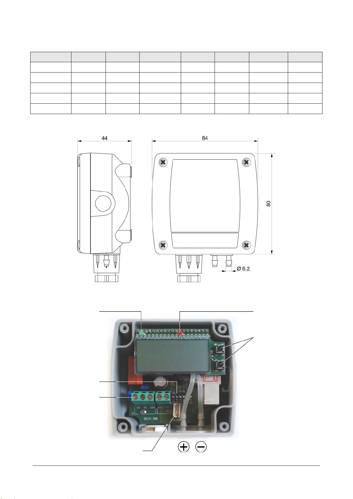
Pressure connection Ø 6.2 mm for tubes with internal Ø 5…6 mm
Electrical connections Screw terminal block, max 1.5 mm2 , PG9 cable gland for the input cable
Operating conditions -10…+60 °C / 0…95% RH
Storage temperature -20…+70 °C
Housing dimensions 80 x 84 x 44 mm
Protection degree IP65
TAB. 1: full scale values and units of measurement
Model Pa kPa mbar mmH2O inchH2O mmHg PSI
HD402TR1L 250 --- 2.5 25 1 --- ---
HD402TR2L 1000 --- 10 100 4 --- ---
HD402TR3L --- 10 100 --- --- 50 1.5
HD402TR4L --- 100 1000 --- --- 500 15
HD402TR5L --- 200 2000 --- --- 1000 30
HD402TR - 5 - V1.0
TAB. 2: resolution
Model Pa kPa mbar mmH2O inchH2O mmHg PSI
HD402TR1L 0.1 --- 0.001 0.01 0.001 --- ---
HD402TR2L 1 --- 0.01 0.1 0.01 --- ---
HD402TR3L --- 0.01 0.1 --- --- 0.01 0.001
HD402TR4L --- 0.1 1 --- --- 0.1 0.01
HD402TR5L --- 0.1 1 --- --- 1 0.01
DIMENSIONS
INTERNAL VIEW
Power LED Alarm LED
Terminal heade
r
Buttons fo
r
configuration and
manual zeroing
Serial por
t
B1
B2
Dip switches
Pressure inputs

HD402TR - 6 - V1.0
3INSTALLATION
The sensor and the electronics are housed in a rugged plastic case with IP 65 protec-
tion degree. By opening the lid, 3 mm diameter holes are available so to allow secur-
ing the base of the instrument directly to a panel or to the wall.
The instrument can be mounted in any position, but typically it is secured on a vertical
wall with the pressure inputs facing down.
In the model HD402TR1L, an auto-zero circuit periodically automatically equalizes the
differential pressure at the input of the sensor and corrects the offset due to the
mounting position or sensor aging. In the other models, the deviation of the zero can
be manually corrected as follows:
•Disconnect both the tubes from the pressure + and – inputs.
•Press B1 and B2 buttons at the same time until the ALARM red LED lights up (if it
was not already on because of an alarm condition) and the instrument displays
the model information and the UP and DOWN arrows on the left of the LCD.
•When the instrument returns to the measurement mode displaying zero read-
ing, reconnect the tubes to the pressure inputs.
If necessary, the manual auto-zero procedure can be performed also in HD402TR1L
(in this case it is not necessary to disconnect the tubes from the pressure inputs).
Except for HD402TR1L (in which the auto-zero procedure is periodic and automatic), it
is recommended to follow the auto-zero procedure at least once a year under normal
operating conditions.
HD402TR - 7 - V1.0
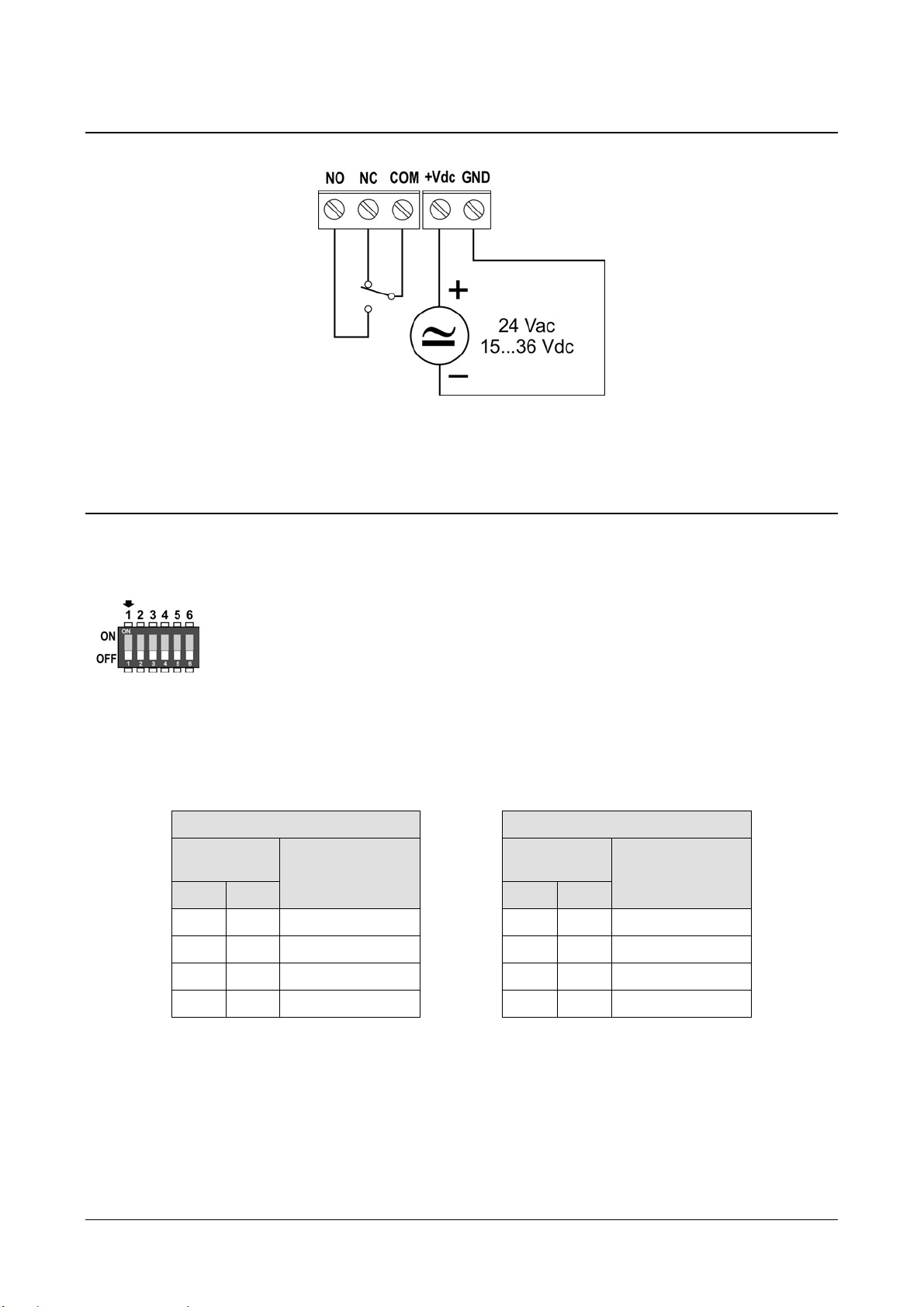
3.1 ELECTRICAL CONNECTIONS
At power on, the alarm LED blinks quickly while the instrument information is displayed.
3.2 CONFIGURATION
The instrument can be configured by using the dip switches (for the unit of measurent)
and the buttons (for alarm settings) on the circuit board or via the COM AUX serial port.
The choice of the configuration mode is done with the dip switch 1:
•Dip switch 1 = ON ⇒the configuration set through the dip switches
4/5 and the buttons is used
•Dip switch 1 = OFF ⇒the configuration set via serial port is used
A dip switch is OFF when placed down, towards the serial connector. Instead, it is ON if
placed up, towards the DIP SW sign.
The following tables report the unit of measurement corresponding to the dip switches
setting.
Models TR1 and TR2 Models TR3, TR4 and TR5
Dip switch
number Unit of
measurement Dip switch
number Unit of
measurement
4 5 4 5
OFF ON inchH2O OFF ON PSI
ON OFF mmH2O ON OFF mmHg
OFF OFF Pa OFF OFF kPa
ON ON mbar ON ON mbar
The dip switches 2, 3 and 6 are not used.
CONFIGURATION VIA THE COM AUX SERIAL PORT
The configuration set with the serial communication is used by the instrument only if
the dip switch 1 is OFF.
In order to modify the settings, proceed as follows:
HD402TR - 8 - V1.0
•Connect the COM AUX serial port of the instrument to the RS232 port (via the
RS27 cable) or USB (via the cable CP27) of the PC. If you use the CP27 cable, in-
stall the USB drivers on your PC.
•On the PC, launch a program for serial communication (e.g. Hyperterminal), set
the baud rate to 115200 and the communication parameters to 8N2.
•Send the CAL START command (the command is required to change the con-
figuratrion; to read the value of the parameters, the command is not required).
•Send the commands given in the table below to set or read the instrument pa-
rameters.
Serial commands
Command Descri
p
tion
G0 Reads the instrument model and range
Example of reply: HD402TR2 1000Pa
If the model has the Auto-zero feature, AZ will appear after the range
G2 Reads the instrument serial number
G3 Reads the instrument firmware version
G4 Reads the instrument firmware date
GD Reads the instrument calibration date
GM Reads the current measurement
Kn Sets the unit of measurement
HD402TR1 and HD402TR2:
n=0 ⇒Pa; n=1 ⇒mmH2O; n=2 ⇒inchH2O; n=4 ⇒mbar
HD402TR3, HD402TR4 and HD402TR5:
n=0 ⇒kPa; n=1 ⇒mmHg; n=2 ⇒PSI; n=4 ⇒mbar
Default: Pa (HD402TR1 / HD402TR2), kPa (HD402TR3 / HD402TR4 / HD402TR5)
AWSn Sets the relay operating mode
n=0 ⇒Negative (NC contact is closed if no alarm, NO contact is closed if in alarm)
n=1 ⇒Positive (NO contact is closed if no alarm, NC contact is closed if in alarm)
Default: Negative
ARS Reads the relay operating mode
AWBn Sets the buzzer activation status: n=0 ⇒OFF; n=1 ⇒ON
Default: OFF
ARB Reads the buzzer activation status
AWAn Sets the alarm activation status: n=0 ⇒OFF; n=1 ⇒ON
Default: OFF
ARA Reads the alarm activation status
AWEn Sets the alarm operating mode
n=0 ⇒Above threshold (alarm is on if measurement is greater than threshold 1)
n=1 ⇒Below threshold (alarm is on if measurement is less than threshold 1)
n=2 ⇒Outside thresholds (alarm is on if measurement is less than threshold 1
or greater than threshold 2)
Default: Above threshold
ARE Reads the alarm operating mode
AWT1snnnn Sets the threshold 1 value to snnnn (“s” is the sign of the value) (*)
Default: pressure value corresponding to 30% of the full scale

HD402TR - 9 - V1.0
Command Descri
p
tion
ART1 Reads the threshold 1 value
AWT2snnnn Sets the threshold 2 value to snnnn (“s” is the sign of the value) (*)
Default: pressure value corresponding to 70% of the full scale
ART2 Reads the threshold 2 value
AWHnnnn Sets the hysteresis value to nnnn (*)
Default: pressure value corresponding to 10% of the full scale
ARH Reads the hysteresis value
AWD1nnn Sets the alarm activation delay to nnn seconds (0… 600 s)
Default: 0
ARD1 Reads the alarm activation delay value
AWD2nnn Sets the alarm deactivation delay to nnn seconds (0… 600 s)
Default: 0
ARD2 Reads the alarm deactivation delay value
(*) The thresholds and hysteresis values are considered in the unit of measurement set
in the instrument. The value must be written without the decimal point, even if it is not
an integer value (e.g., to set thresholds 1 to +1.500, write AWT1+1500). Leading zeros
can be omitted (e.g., to set thresholds 1 to +0.050, write AWT1+50).
To exit the configuration mode after sending the CAL START command, send the
CAL END command (the instrument automatically exits the configuration mode after 5
minutes from the last command sent).
CONFIGURATION VIA THE INTERNAL BUTTONS
The configuration set with the internal buttons is used by the instrument only if the
dip switch 1 is ON.
The upper button B1 allows scrolling the available operating parameters, while the
lower button B2 allows changing the setting of the selected parameter.
The function of a button depends on whether it is short or long pressed. To short
press a button, hold it down for about 1 second, until the power LED turns off. To long
press a button, hold it down for at least 3 seconds, until the power LED turns off and then
turns on again.
Long press the upper button B1 to enter the menu. Inside the menu, long press B1 to
scroll the available parameters. Below is the sequence of the operating parameters (in
brackets the indication that appears on the display) with the possible settings for non-
numerical parameters:
•Relay operating mode (SECU):
oNegative (NEG): NC contact is closed if no alarm, NO contact is closed if in alarm
oPositive (POS): NO contact is closed if no alarm, NC contact is closed if in alarm
•Buzzer activation (BEEP):
oOFF: buzzer disabled
oON: buzzer enabled
•Alarm activation (ALAR):
oOFF: alarm disabled
oON: alarm enabled

HD402TR - 10 - V1.0
•Alarm operating mode (EDGE):
oAbove threshold (RISE): alarm is on if measurement is greater than threshold 1
oBelow threshold (FALL): alarm is on if measurement is less than threshold 1
oOutside thresholds (OUTS): alarm is on if measurement is less than threshold 1
or greater than threshold 2
•Threshold 1 (THR1): Value of the threshold for above (RISE) and below (FALL)
alarm operating modes; value of the lower threshold for outside thresholds (OUTS)
alarm operating mode.
•Threshold 2 (THR2): Value of the upper threshold for outside thresholds (OUTS)
alarm operating mode. The parameter appears only if the alarm operating mode
is set to OUTS.
•Hysteresis (HYST): Value of the hysteresis for above (RISE) and below (FALL)
threshold alarm operating modes. The parameter does appear if the alarm operat-
ing mode is set to OUTS.
•Alarm activation delay (T1): Value in seconds of the time delay for generating
the alarm. The alarm is generated only if the measurement exceeds the thre-
shold for more than the set time.
•Alarm deactivation delay (T2): Value in seconds of the time delay for deactivat-
ing the alarm. The alarm is deactivated only after the set time has elapsed from the
disappearance of the alarm condition.
Note: the EDGE, THR1, THR2, HYST, T1 and T2 parameters do not appear if the alarm
is set to OFF.
Changing non-numerical parameters:
•Select the parameter by using the button B1.
•Short press the button B2 to change the setting.
•Long press the button B1 to move to the next parameter.
Changing numerical parameters:
•Select the parameter by using the button B1.
•Short press the button B2 to change the sign.
•Long press the button B2 to select the first digit.
•Short press the button B2 to change the selected digit.
•Long press the button B2 to select the next digit.
•Repeat the above two steps until all the digits are set.
•Long press the button B1 to move to the next parameter.
While a parameter value is displayed, a short press of the button B1 will briefly show
the name of the currently selected parameter.
HD402TR - 11 - V1.0
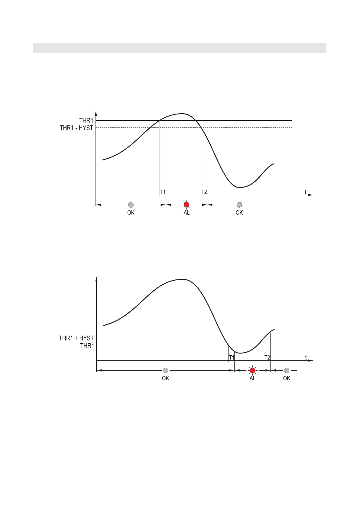
4ALARM OPERATING MODES
Above threshold (RISE): the alarm is turned on if the measurement is greater than
threshold 1 for more than T1 seconds. The alarm is turned off when the measurement
becomes less then threshold 1 minus the hysteresis for more than T2 seconds.
The up arrow on the left of the display is shown when this mode is selected.
Below threshold (FALL): the alarm is turned on if the measurement is less than
threshold 1 for more than T1 seconds. The alarm is turned off when the measurement
becomes greater then threshold 1 plus the hysteresis for more than T2 seconds.
The down arrow on the left of the display is shown when this mode is selected.
Outside thresholds (OUTS): the alarm is turned on if the measurement is greater
than threshold 2 or less than threshold 1 for more than T1 seconds. The alarm is turned
off when the measurement returs between the two thresholds for more than T2 seconds.
No hysteresis is applied to the thresholds.
The up and down arrows on the left of the display are shown when this mode is se-
lected.

HD402TR - 12 - V1.0
When the measurement is in alarm, the red LED lights up, the buzzer is on (if
enabled) and the relay is switched (depending on the chosen relay operating mode).
While in alarm, the buzzer can be stopped (only for the current event) by short press-
ing the button B1.
The alarm is disabled while in the configuration menu.

HD402TR - 13 - V1.0
5INSTRUMENT STORAGE
Instrument storage conditions:
•Temperature: -20...+70 °C.
•Humidity: less than 90 %RH no condensation.
•In storage, avoid places where:
•humidity is high;
•the instrument is exposed to direct sun radiation;
•the instrument is exposed to a high temperature source;
•high vibration levels are present;
•the instrument may be exposed to vapor, salt and/or corrosive gas.
6SAFETY INSTRUCTIONS
General safety instructions
The instrument has been manufactured and tested in accordance with the safety
standard EN61010-1:2010 “Safety requirements for electrical equipment for mea-
surement, control and laboratory use” and has left the factory in perfect safety tech-
nical conditions.
The instrument proper operation and operating safety can be ensured only if all stan-
dard safety measures as well as the specific measures described in this manual are
followed.
The instrument proper operation and operating safety can be ensured only in the cli-
matic conditions specified in this manual.
Do not use the instruments in places where there are:
•Corrosive or flammable gases.
•Direct vibrations or shocks to the instrument.
•High-intensity electromagnetic fields, static electricity.
User obligations
The instrument operator shall follow the directives and regulations below that refer to
the treatment of dangerous materials:
•EEC directives on workplace safety.
•National law regulations on workplace safety.
•Accident prevention regulations.

HD402TR - 14 - V1.0
7ORDERING CODES
HD402TR…L Relative or differential pressure controller with ON/OFF relay switch.
Range from ±250 Pa to ±200 kPa depending on model. 4-digit LCD dis-
play. User configurable via serial port or internal buttons. Operating
temperature -10...+60 °C. Suitable for measuring non-corrosive gases
or dry air. Ø 6.2 mm pressure inputs for tubes with internal Ø 5…6
mm. Power supply 24 Vac or 15...36 Vdc.
AP3719 Flow port for for square or cylindrical duct.
AP3721 Plastic flow port for cylindrical duct.
RS27 RS232 null-modem serial connection cable with SubD 9-pin connector on
the PC side and 3-pole connector on the instrument side.
CP27 Connection cable with built-in USB/RS232 converter. USB connector on the
PC side and 3-pole connector on the instrument side.
DELTA OHM metrology laboratories LAT N° 124 are ISO/IEC 17025 accredited by AC-
CREDIA for Temperature, Humidity, Pressure, Photometry / Radiometry, Acoustics and
Air Velocity. They can supply calibration certificates for the accredited quantities.
HD402T
R
L
Ran
g
e:
1= ± 250 Pa / 25 mmH2O / 1 inchH2O / 2,5 mbar
2= ± 1000 Pa / 100 mmH2O / 4 inchH2O / 10 mbar
3= ± 10 kPa / 50 mmHg / 1,5 PSI / 100 mbar
4= ± 100 kPa / 500 mmHg / 15 PSI / 1000 mbar
5= ± 200 kPa / 1000 mmHg / 30 PSI / 2000 mbar


GUARANTEE
TERMS OF GUARANTEE
All DELTA OHM instruments are subject to accurate testing, and are guaranteed for 24 months from the
date of purchase. DELTA OHM will repair or replace free of charge the parts that, within the warranty
period, shall be deemed non efficient according to its own judgement. Complete replacement is excluded
and no damage claims are accepted. The DELTA OHM guarantee only covers instrument repair. The
guarantee is void in case of incidental breakage during transport, negligence, misuse, connection to a
different voltage than that required for the appliance by the operator. Finally, a product repaired or
tampered by unauthorized third parties is excluded from the guarantee. The instrument shall be returned
FREE OF SHIPMENT CHARGES to your dealer. The jurisdiction of Padua applies in any dispute.
The electrical and electronic equipment marked with this symbol cannot be disposed of in public
landfills. According to the Directive 2011/65/EU, the european users of electrical and electronic
equipment can return it to the dealer or manufacturer upon purchase of a new one. The illegal
disposal of electrical and electronic equipment is punished with an administrative fine.
This guarantee must be sent together with the instrument to our service centre.
IMPORTANT: Guarantee is valid only if coupon has been correctly filled in all details.
Instrument Code: HD402TR…L
Serial Number
RENEWALS
Date Date
Inspector Inspector
Date Date
Inspector Inspector
Date Date
Inspector Inspector

GHM GROUP – Delta OHM | Delta Ohm S.r.l. a socio unico
Via Marconi 5 | 35030 Caselle di Selvazzano | Padova | ITALY
Phone +39 049 8977150 | Fax +39 049 635596
www.deltaohm.com | info@deltaohm.com
The quality level of our instruments is the result of the constant development of the product. This may
produce some differences between the information written in this manual and the instrument you have
purchased. We cannot completely exclude the possibility of errors in the manual, for which we apologize.
The data, images and descriptions included in this manual cannot be legally asserted. We reserve the
right to make changes and corrections with no prior notice.

GHM GROUP – Delta OHM | Delta Ohm S.r.l. a socio unico
Via Marconi 5 | 35030 Caselle di Selvazzano | Padova | ITALY
Phone +39 049 8977150 | Fax +39 049 635596
www.deltaohm.com | info@deltaohm.com
V1.0
05/06/2019
Table of contents
Other Delta OHM Transmitter manuals

Delta OHM
Delta OHM DO 9403T-R1 User manual

Delta OHM
Delta OHM DO 9861T User manual

Delta OHM
Delta OHM HD45 Series User manual

Delta OHM
Delta OHM PMsense User manual

Delta OHM
Delta OHM HD9408.3B User manual

Delta OHM
Delta OHM HD402TR Series User manual

Delta OHM
Delta OHM HD45 17V User manual

Delta OHM
Delta OHM HD2817T Series User manual


