Delta OHM PMsense User manual

Operating manual
PM / CO2Transmitter
PM[B]sense
www.deltaohm.com
English
Keep for future reference.

PM[B]sense
- 2 -
V1.3
TABLE OF CONTENTS
1 INTRODUCTION ........................................................................................ 3
2 TECHNICAL SPECIFICATIONS ................................................................... 3
3 INSTALLATION .........................................................................................
3.1 E
LECTRICAL CONNECTIONS
.......................................................................... 5
4 CONFIGURATION AND MEASUREMENT ..................................................... 8
PROPRIETARY PROTOCOL ........................................................................ 9
6 MODBUS-RTU PROTOCOL ........................................................................ 1
7 SAFETY INSTRUCTIONS .......................................................................... 19
8 ACCESSORIES ORDERING CODES ........................................................... 21

PM[B]sense
- 3 -
V1.3
1 INTRODUCTION
PMsense is a PM1.0, PM2. and PM10 Par icula e Ma er ransmi er sui able for
ou door air quali y moni oring.
The dus par icles concen ra ion is measured using he laser sca ering principle.
An op ional CO
2
sensor can be in egra ed in he ransmi er (PMBsense).
The ransmi er has a digi al RS485 ou pu wi h MODBUS-RTU or ASCII proprie ary
pro ocol. A version wi h wo addi ional 0/4…20 mA (0…10 V on request when order-
ing) analog ou pu s is available. The wo analog ou pu s can be independen ly associ-
a ed wi h any of he measured parame ers.
The measuring circui of he ransmi er can be opera ed in con inuous mode or, in
order o ex end he PM sensor life ime, a cyclic in ervals (defaul opera ing mode).
The measuring cycle in erval is user configurable.
The ransmi er is main enance-free and has fas response, high sensi ivi y, excellen
s abili y and long opera ing life.
Models
Measurement Output
Model PM CO
2
RS48 Analog
(*)
PMsense-M √ √
PMsense-A √ √ √
PMBsense-M √ √ √
PMBsense-A √ √ √ √
(*)
Two analog ou pu s, s andard 0/4…20 mA, on reques 0…10 V.

PM[B]sense
- 4 -
V1.3
2TECHNICAL SPECIFICATIONS
Particulate Matter
Measuring principle Laser sca ering
Measured pollu an s PM1.0, PM2.5 and PM10
Measuring range 0…1000 µg/m
3
(for each pollu an )
Par icle size de ec ion range ∅ 0.3…10 µm
Lineari y error < 5%
Repea abili y < 3%
Sensor warm up ime 15 s
Sensor life ime 5 years approx. in 5 minu es cyclic opera ing mode (defaul )
> 10,000 hours in con inuous opera ing mode (1 meas./s)
Tempera ure drif < 0.01 µg/m
3
/°C
CO
2
(only PMBsense…)
Measuring principle Double waveleng h NDIR
Measuring range 0…5000 ppm
Accuracy ±(50 ppm+3% of measuremen ) @ 25 °C and 1013 hPa
Response ime < 120 s (air speed= 2 m/s)
Long- erm s abili y 5% of measuremen / 5 years
Tempera ure drif 1 ppm/°C
General specifications
Ou pu RS485 wi h Modbus-RTU or ASCII proprie ary pro ocol
Only PMsense-A: 2 x analog 4…20 mA (R
Lmax
= 500 Ω); on
reques 2 x 0…10 V (R
Lmin
= 10 kΩ)
Power supply 7…30 Vdc
(15…30 Vdc for 0…10 V analog ou pu s)
Power consump ion 25 mA @ 24 Vdc during measuremen
4 mA in s and-by (only for cyclic opera ing mode)
The indica ed consump ion does no include he consump ion
due o he analog ou pu s
Connec ion M12 8-pole circular connec or
Opera ing condi ions -20…+70 °C / 0…95 %RH / 500…1500 hPa
Housing ma erial Polycarbona e
Pro ec ion degree Housing equipped wi h a rain-proof and UV resis an inle air
fil er – IP 53
Dimensions 120 x 94 x 71 (excluding M12 connec or)
Weigh 330 g

PM[B]sense
- 5 -
V1.3
3INSTALLATION
The ransmi er is equipped wi h a bracke wi h U-bol for he fixing o a Ø40…50 mm
mas . I can be fixed o a wall using he bracke only, by removing he U-bol .
Fig. 3.1: transmitter description
3.1 E
LECTRICAL CONNECTIONS
The ransmi er has a M12 8-pole circular connec or and uses he CPM12-8PM... op-
tional cables, wi h M12 8-pole connec or on one side and open wires on he o her side.
12
3
456
7
81 2
3
4
5
6
78
Fig. 3.2: connectors pinout
Transmi er male
connec or
(ex ernal view)
Connec or
Fixing b
racke wi h
U
-
bol
Air ou le
Air inle
Cable female connec or
(ex ernal view)
Connec or reference
PM[B]sense
- 6 -
V1.3
Connector
pin N° Function CPM12-8PM…
wire color
1 Power supply nega ive (GND) Blue
2 Power supply posi ive (+Vdc) Red
3 No used ---
4 RS485 A/- Brown
5 RS485 B/+ Whi e
6 Digi al and analog ou pu s ground (SGND)* Grey
7 Analog ou pu 1 posi ve (AOUT1, only PM[B]sense-A) Yellow
8 Analog ou pu 2 posi ve (AOUT2, only PM[B]sense-A) Green
Cable shield ** Black ( hick wire)
* The ou pu ground (SGND) and he nega ive of he power supply (GND) are shor -circui ed
inside he ransmi er.
* The cable shield is no connec ed o he M12 connec or.
To ensure a good noise immuni y, i is recommended o connec he cable shield o
ground (GND).
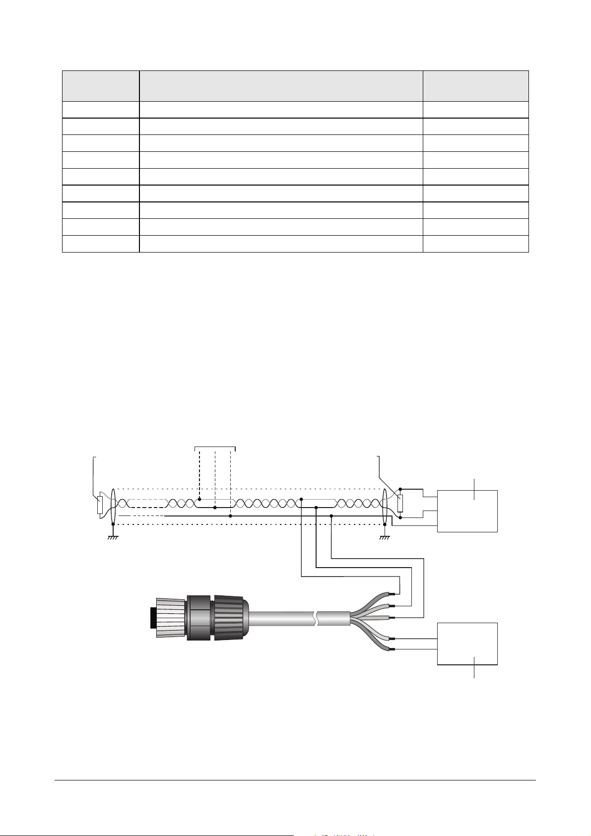
RS48 connection:
By defaul , he ins rumen has MODBUS address 1 and communica ion parame ers
19200, 8E1. Differen parame ers can be se using he proprie ary pro ocol or he
MODBUS-RTU pro ocol.
220Ω
220Ω ShieldShield
Lmax = 1200m
B/+
A/-
B/+
A/-
SGND
GND
+Vdc
B/+
A/-
SGND
+
-
Fig. 3.3: RS48 connection
Power supply
7…30 Vdc
CPM12-8PM… cable
PLC, da a logger or
RS485/USB or RS485/RS232
conver er for PC
O her sensors wi h
RS485 ou pu
Termina ion Termina ion
PM[B]sense
- 7 -
V1.3
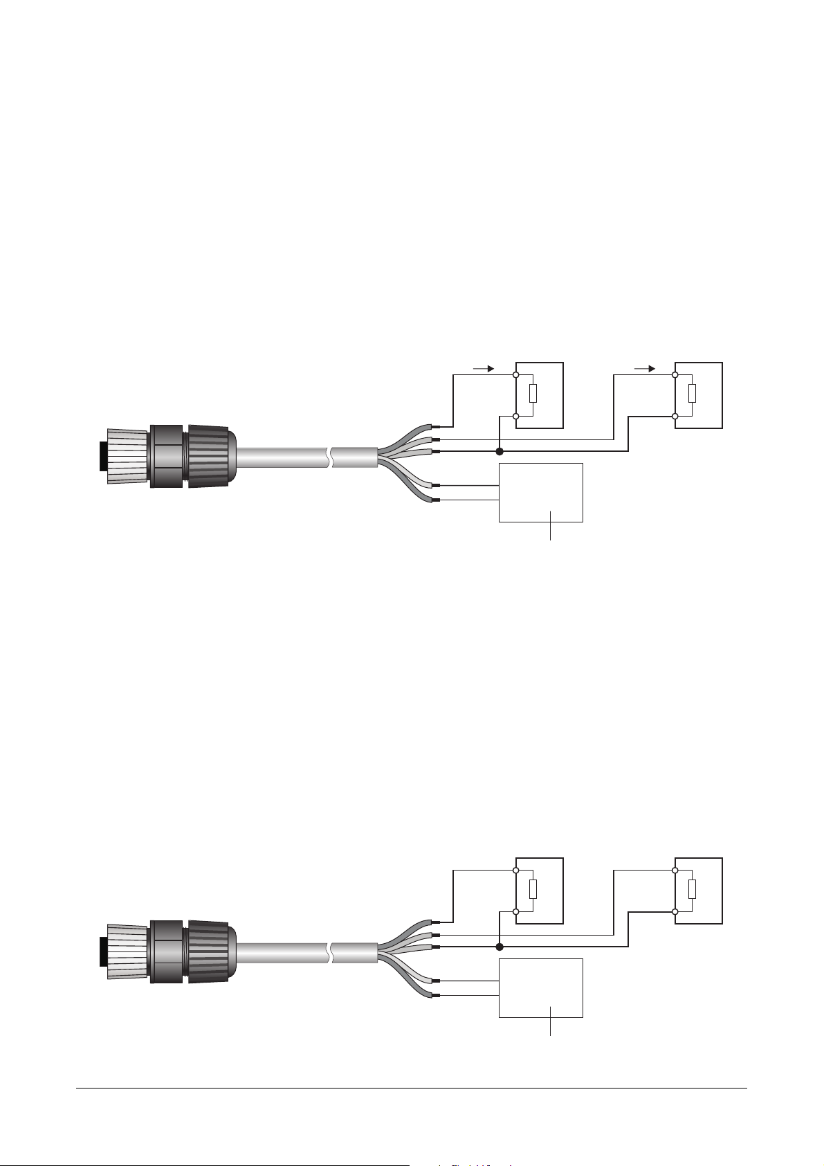
Current analog output (only PM[B]sense-A):
By defaul , he curren analog ou pu s are 4…20 mA, wi h:
4 mA = 0 µg/m
3
20 mA = 1000 µg/m
3
The analog ou pu 1 is associa ed by defaul o PM2.5. The analog ou pu 2 is associ-
a ed by defaul o PM10.
Wi h he commands of he proprie ary pro ocol i is possible o associa e he analog
ou pu s o differen parame ers, se he range 0…20 mA for he ou pu and reverse he
direc ion of he ou pu , so ha he ou pu decreases as he measuremen increases.
In case of measuremen error, he ou pu goes o 22 mA.
I
0/4...20 mA
OUT1
+
-
RL
I
0/4...20 mA
OUT2
+
-
RL
SGND
AOUT1
GND
+Vdc +
-
AOUT2
Fig. 3.4: current analog outputs connection
Voltage analog output (optional, only PM[B]sense-A):
By defaul , he vol age analog ou pu s are 0…10 V, wi h:
0 V = 0 µg/m
3
10 V = 1000 µg/m
3
The analog ou pu 1 is associa ed by defaul o PM2.5. The analog ou pu 2 is associ-
a ed by defaul o PM10.
Wi h he commands of he proprie ary pro ocol i is possible o associa e he analog
ou pu s o differen parame ers, se he range 2…10 V for he ou pu and reverse he
direc ion of he ou pu , so ha he ou pu decreases as he measuremen increases.
In case of measuremen error, he ou pu goes o 11 V.
+
-
RL
+
-
RL
SGND
AOUT1
V
0...10 V
OUT1
V
0...10 V
OUT2
GND
+Vdc
+
-
AOUT2
Fig. 3. : voltage analog outputs connection
Power supply 12…30 Vdc
R
Lmax
= 500 Ω
CPM12-8PM… cable
Power supply 15…30 Vdc
CPM12-8PM… cable
R
Lmin
= 10 kΩ

PM[B]sense
- 8 -
V1.3
4CONFIGURATION AND MEASUREMENT
The configura ion of he ins rumen and he reading of he measuremen s can be done
via he RS485 serial ou pu , bo h wi h he proprie ary pro ocol and wi h he MODBUS-
RTU pro ocol.
In he firs 10 seconds af er he ins rumen power on, i is always ac ive he proprie-
ary pro ocol. Af er 10 seconds from power on, he opera ing pro ocol is ac iva ed,
which by defaul is he MODBUS-RTU pro ocol.
I is possible o keep he proprie ary pro ocol ac ive even af er 10 seconds from power on
by sending, before he 10 seconds expire, he command @ of he proprie ary pro ocol.
The proprie ary pro ocol can be se as opera ing pro ocol by means of he DP0 command.
The commands of he proprie ary pro ocol and he regis ers of he MODBUS-RTU pro-
ocol are described in de ail in he following chap ers.
Particulate Matter measurement modes:
The ransmi er can perform he PM measuremen in con inuous mode or, in order o
ex end he sensor life ime, a cyclic in ervals (defaul ).
In he measuremen mode a cyclic in ervals, he PM sensor is ac iva ed periodically
for he ON ime. The measuremen is made available af er 70 seconds from sensor ac-
iva ion (warm-up ime). A he end of he ON ime, he measuremen is "frozen" and
he sensor is deac iva ed un il he se cyclic measuremen in erval expires.
Fig. 4.1: Measurement mode at cyclic intervals
The measuremen mode, he cycle in erval and he sensor ON ime can be configured
respec ively by using he CPLS, CPLP and CPLO commands of he proprie ary pro ocol
or he holding regis ers wi h address 15, 16 and 18 of he MODBUS-RTU pro ocol.
The ransmi er provides hree ypes of measuremen s:
•average over a 10 seconds in erval, upda ed every second;
•average over a 60 seconds in erval, upda ed every 10 seconds;
•average over a 15 min in erval, upda ed every minu e.
For he measuremen mode a cyclic in ervals, he cycle in erval and he ON ime
mus be se consis en ly wi h he desired averaging in erval.
Status of the transmitter:
There are wo LEDs on he in ernal elec ronic board of he ransmi er: he green LED
indica es he presence of he ex ernal power supply (blinks once per second), he red
LED indica es he presence of any measuremen errors (normally off, i blinks wice
per second if a leas one of he measured parame ers is in error).
ON ime
Cycle in erval
Sensor ON
Sensor OFF

PM[B]sense
- 9 -
V1.3
PROPRIETARY PROTOCOL
To use he proprie ary pro ocol, i is necessary o connec he ins rumen o he PC via
a RS485/USB (e.g. RS51K) or RS485/RS232 conver er and use a s andard serial
communica ion program. In he serial communica ion program, se he COM por
number o which he ins rumen is connec ed and he communica ion parame ers as
follows:
•If he MODBUS-RTU pro ocol is se as he opera ing pro ocol in he ins rumen
(defaul ), se he Baud Ra e 57600 and he parame ers 8N2 in he serial commu-
nica ion program, hen power cycle he ins rumen and send he command @
wi hin 10 seconds from he ins rumen power on.
•If he proprie ary pro ocol is already se as he opera ing pro ocol in he ins ru-
men , i is possible o opera e wi h Baud Ra e 57600 and parame ers 8N2 by
sending he command @ wi hin 10 seconds from he ins rumen power on, or
you can le he 10 seconds pass wi hou sending he command @ and opera e
wi h he communica ion parame ers se in he ins rumen (defaul 19200, 8E1).
To change he ins rumen configura ion, he serial command CAL USER ON mus be
sen firs ( he ins rumen replies wi h USER CAL MODE ON). The command CAL USER ON
is au oma ically disabled af er a few minu es of inac ivi y. If he se ings should be only
read, he command CAL USER ON is no required.
Below is he lis of he serial commands.
Instrument information:
Command Reply Description
G0 Model Ins rumen model
G1 &Revision| Ins rumen hardware revision
G2 SN=nnnnnnnn Ins rumen serial number
G3 Firm.Ver.=x.y Ins rumen firmware revision
G4 Firm.Da e=yyyy/mm/dd Da e of firmware revision
GC Fac .Calib.Da e= yyyy/mm/dd
User.Calib.Da e= yyyy/mm/dd
Cal.Mode=Factory or User
Da e of fac ory calibra ion
Da e of user calibra ion (CO
2
only)
Type of calibra ion ac ive (CO
2
only)
Protocol:
Command Reply Description
@ &| Keeps he proprie ary pro ocol opera ional even af er 10
seconds from ins rumen power on. I mus be sen wi hin
10 seconds from ins rumen power on.
DPn &| Se s he opera ing pro ocol:
Proprie ary if n=0
MODBUS-RTU if n=1
Default : MODBUS-RTU (n=1)
GP & n| Reads he opera ing pro ocol se in he ins rumen .
SM &| Ac iva es he MODBUS-RTU pro ocol immedia ely.
CMAn &| Se s he ins rumen address for he MODBUS-RTU pro-
ocol o n.
The address should range wi hin 1 and 247.
Default : 1
RMA & n| Reads he ins rumen address for he MODBUS-RTU pro-
ocol.

PM[B]sense
- 10 -
V1.3
Note: af er sending he DP1 command, he ins rumen remains wi h he proprie ary pro ocol.
Send he command SM o ac iva e he MODBUS-RTU pro ocol immedia ely, or power cycle he
ins rumen .
RS48 communication parameters:
Command Reply Description
CMBn &| Se s he Baud Ra e:
1200 if n=0
▪
19200 if n=4
2400 if n=1
▪
38400 if n=5
4800 if n=2
▪
57600 if n=6
9600 if n=3
▪
115200 if n=7
Default : 19200 (n=4)
RMB & n| Reads Baud Ra e se ing
CMPn &| Se s pari y and s op bi s:
8N1 if n=0 [No pari y, 1 s op bi ]
8N2 if n=1 [No pari y, 2 s op bi s]
8E1 if n=2 [Even pari y, 1 s op bi ]
8E2 if n=3 [Even pari y, 2 s op bi s]
8O1 if n=4 [Odd pari y, 1 s op bi ]
8O2 if n=5 [Odd pari y, 2 s op bi s]
The number of da a bi s is fixed o 8.
Default : 8E1 (n=2)
RMP & n| Reads he se ing of pari y and s op bi s.
CMWn &| Se s wai ing ime af er ransmission wi h MODBUS-RTU
pro ocol:
Immedia e recep ion if n=0 (viola es pro ocol)
Wai ing 3.5 charac ers if n=1 (respec s pro ocol)
Default : Immedia e recep ion (n=0)
RMW & n| Reads he se ing of wai ing ime af er ransmission wi h
MODBUS-RTU pro ocol.
PM measurement settings:
Command Reply Description
CPLSn &| Se s he PM measuremen mode:
Con inuous if n=0
A cyclic in ervals if n=1
Default : A cyclic in ervals (n=1)
RPLS & n| Reads he se ing of he PM measuremen mode.
CPLPn &| Se s he cycle in erval for he measuremen mode a cy-
clic in ervals.
Default : 300 (=5 min)
RPLP & n| Reads he se ing of he cycle in erval for he measure-
men mode a cyclic in ervals.
CPLOn &| Se s he sensor ON ime for he measuremen mode a
cyclic in ervals o n seconds.
I mus be grea er han 70 s (warm-up ime).
Default : 71
RPLO & n| Reads he se ing of he sensor ON ime for he measure-
men mode a cyclic in ervals.

PM[B]sense
- 11 -
V1.3
Reading of the measurement information:
Command Reply Description
CPSn &| Se s he ype of PM measuremen averaging for he ana-
log ou pu s and he measuremen s sen by he ransmi er
in reply o P1, P5, S1 and S5 commands or when reading
MODBUS Inpu Regis ers 0…5:
Average over a 10 seconds in erval, upda ed every
second if n=0
Average over a 60 seconds in erval, upda ed every
10 seconds if n=1
Average over a 15 minu es in erval, upda ed every
minu e if n=2
Default : Average over a 10 seconds in erval, upda ed
every second (n=0)
RPS & n| Reads he ype of averaging for he measuremen s sen by
he ransmi er in reply o P1, P5, S1 and S5 commands.
P0 &| Disable he sending of he measuremen enabled wi h P1.
P1 &| Enable he sending of he PM measuremen every second
( he sequence is he same described in command P5).
P5 & Measurements Prin s he PM measuremen s in he following sequence:
PM measuremen error (0=no, 1=yes)
PM1.0 in N° of par icles/ml
PM2.5 in N° of par icles/ml
PM10 in N° of par icles/ml
PM1.0 in µg/m
3
PM2.5 in µg/m
3
PM10 in µg/m
3
The PM measurement is averaged according to what is set
with CPS command or MOD US holding register 19.
S0 &| Disable he sending of he measuremen enabled wi h S1.
S1 &| Enable he sending of he measuremen every second
( he sequence is he same described in command S5).
S5 & Measurements Prin s he measuremen s in he following sequence:
PM measuremen error (0=no, 1=yes)
PM1.0 in µg/m
3
PM2.5 in µg/m
3
PM10 in µg/m
3
CO
2
in ppm
A mospheric pressure in hPa (in ernal sensor for
CO
2
measuremen compensa ion)
Field not used
Field not used
Field not used
Power supply vol age
In ernal board empera ure
The PM measurement is averaged according to what is set
with CPS command or MOD US holding register 19.

PM[B]sense
- 12 -
V1.3
Analog outputs (only PM[B]sense-A):
Command Reply Description
CA1On &| Enable/disable he offse of he analog ou pu 1:
Offse disabled if n=0 (0…20 mA or 0…10 V)
Offse enabled if n=1 (4…20 mA or 2…10 V)
Default : Offse enabled (n=1) if he ou pu is curren ,
offse disabled (n=0) if he ou pu is vol age (op ional)
RA1O & n| Reads he se ing of he offse for he analog ou pu 1.
CA1SOn &| Se s he direc or inverse correspondence be ween analog
ou pu 1 and associa ed physical quan i y:
4 mA/0 V Min. quan i y, 20 mA/10 V Max.
quan i y if n=0
20 mA/10 V Min. quan i y, 4 mA/0 V Max.
quan i y if n=1
Default : Direc correspondence (n=0)
RA1SO & n| Reads he ype of correspondence (direc or inverse) be-
ween analog ou pu 1 and associa ed physical quan i y.
CA1Tn &| Associa es he analog ou pu 1 o:
PM1.0 if n=0
PM2.5 if n=1
PM10 if n=2
CO
2
if n=12 (only PMBsense-A)
Default : PM2.5 (n=1)
The PM measurement is averaged according to what is set
with CPS command or MOD US holding register 19.
RA1T & n| Reads he physical quan i y associa ed o analog ou pu 1.
CA1Ln &| Se s n as he minimum value of he measuring range of
he physical quan i y associa ed o he analog ou pu 1.
If he ou pu is associa ed o PM, he value mus be ex-
pressed as a number of en hs (e.g. n=5 o indica e 0.5
µg/m
3
). If he ou pu is associa ed o CO
2
, he value mus
be expressed as a number of uni s (e.g. n=200 o indica e
200 ppm).
Default : 0
RA1L & n| Reads he minimum value of he measuring range of he
physical quan i y associa ed o he analog ou pu 1.
CA1Hn &| Se s n as he maximum value of he measuring range of
he physical quan i y associa ed o he analog ou pu 1.
If he ou pu is associa ed o PM, he value mus be ex-
pressed as a number of en hs (e.g. n=50 o indica e 5.0
µg/m
3
). If he ou pu is associa ed o CO
2
, he value mus
be expressed as a number of uni s (e.g. n=800 o indica e
800 ppm).
Default : 10000 (=1000.0 µg/m
3
of PM)
RA1H & n| Reads he maximum value of he measuring range of he
physical quan i y associa ed o he analog ou pu 1.
RA1F & Quantity
Minimum value
Maximum value
Simul aneously provides he informa ion ob ainable wi h
he RA1T, RA1L e RA1H commands.

PM[B]sense
- 13 -
V1.3
Command Reply Description
CA2On &| Enable/disable he offse of he analog ou pu 2:
Offse disabled if n=0 (0…20 mA or 0…10 V)
Offse enabled if n=1 (4…20 mA or 2…10 V)
Default : Offse enabled (n=1) if he ou pu is curren ,
offse disabled (n=0) if he ou pu is vol age (op ional)
RA2O & n| Reads he se ing of he offse for he analog ou pu 2.
CA2SOn &| Se s he direc or inverse correspondence be ween analog
ou pu 2 and associa ed physical quan i y:
4 mA/0 V Min. quan i y, 20 mA/10 V Max.
quan i y if n=0
20 mA/10 V Min. quan i y, 4 mA/0 V Max.
quan i y if n=1
Default : Direc correspondence (n=0)
RA2SO & n| Reads he ype of correspondence (direc or inverse) be-
ween analog ou pu 2 and associa ed physical quan i y.
CA2Tn &| Associa es he analog ou pu 2 o:
PM1.0 if n=0
PM2.5 if n=1
PM10 if n=2
CO
2
if n=12 (only PMBsense-A)
Default : PM10 (n=2)
The PM measurement is averaged according to what is set
with CPS command or MOD US holding register 19.
RA2T & n| Reads he physical quan i y associa ed o analog ou pu 2.
CA2Ln &| Se s n as he minimum value of he measuring range of
he physical quan i y associa ed o he analog ou pu 2.
If he ou pu is associa ed o PM, he value mus be ex-
pressed as a number of en hs (e.g. n=5 o indica e 0.5
µg/m
3
). If he ou pu is associa ed o CO
2
, he value mus
be expressed as a number of uni s (e.g. n=200 o indica e
200 ppm).
Default : 0
RA2L & n| Reads he minimum value of he measuring range of he
physical quan i y associa ed o he analog ou pu 2.
CA2Hn &| Se s n as he maximum value of he measuring range of
he physical quan i y associa ed o he analog ou pu 2.
If he ou pu is associa ed o PM, he value mus be ex-
pressed as a number of en hs (e.g. n=50 o indica e 5.0
µg/m
3
). If he ou pu is associa ed o CO
2
, he value mus
be expressed as a number of uni s (e.g. n=800 o indica e
800 ppm).
Default : 10000 (=1000 µg/m
3
of PM)
RA2H & n| Reads he maximum value of he measuring range of he
physical quan i y associa ed o he analog ou pu 2.
RA2F & Quantity
Minimum value
Maximum value
Simul aneously provides he informa ion ob ainable wi h
he RA2T, RA2L e RA2H commands.

PM[B]sense
- 14 -
V1.3
CO
2
calibration (only PMBsense…):
A 2-poin (CO21 and CO22 commands) or 1-poin calibra ion (CO2O command) can
be performed. The poin s are chosen by he user. To perform he calibra ion, he
ransmi er mus be placed in an environmen wi h a known CO
2
concen ra ion.
While he 2-poin calibra ion allows moving he wo calibra ion poin s independen ly,
and herefore also o adjus he slope of he sensor response curve, he 1-poin cali-
bra ion simply adds an offse o he measuremen ( he wo calibra ion poin s are
shif ed of he same amoun ) and is ypically accomplished by placing he ransmi er
in clean air.
Before performing he calibra ion, he ype of calibra ion o be used mus be se o
“user” wi h he CC command.
The ransmi er allows manually se ing, wi h he DA command, a s ring ha is saved
as he da e and ime of he calibra ion. The s ring mus be se before performing he
calibra ion.
Command Reply Description
CO21n & | CO
2
calibra ion in he firs poin a n ppm.
The ransmi er mus firs be placed in an environmen
wi h a known CO
2
concen ra ion ( he value n en ered in
he command).
The value in he reply o he command indica es he
number of seconds required for he ransmi er o com-
ple e he calibra ion opera ion. During his ime, he
ransmi er sends s rings no ifying he progress of he
opera ion; for example:
“CO2 calib. S a us:IN PROGRESS 8% Avg:1096ppm Dev:0ppm”
A he end, he OK 100% no ifica ion indica es ha he
opera ion was successful; for example:
“CO2 calib. S a us:OK 100% Avg:1100ppm Dev:7ppm”
CO22n & | CO
2
calibra ion in he second poin a n ppm.
Opera ion similar o he CO21command.
CO2On & | CO
2
calibra ion a n ppm (1-poin calibra ion – offse ad-
jus men ).
Opera ion similar o he CO21command.
DAyyyy/mm/dd
hh:mm:ss
&| Saves he s ring “aaaa/mm/gg hh:mm:ss” as he da e
and ime when calibra ion is performed.
The command mus be sen before performing he cali-
bra ion.
GA & yyyy/mm/dd
hh:mm:ss
Reads he da e and ime saved wi h he DA command.
CCn &| Se s he ype of calibra ion o be used:
User if n=0
Fac ory if n=1
Default : Fac ory (n=1)
CO2D &| Rese of user calibra ion.
Restoring the factory configuration:
Command Reply Description
DFLT &| Res ores he fac ory configura ion.

PM[B]sense
- 15 -
V1.3
6MODBUS-RTU PROTOCOL
By defaul , he ins rumen has MODBUS address 1 and communica ion parame ers
19200, 8E1. The address and he communica ion parame ers can be changed by using
he appropria e serial commands of he proprie ary pro ocol or, al erna ively, direc ly
wi h MODBUS commands by changing he value of he Coils and Holding Regis ers de-
scribed la er.
The MODBUS-RTU pro ocol, if se as he opera ing pro ocol (defaul ), is ac ive af er 10
seconds from he ins rumen power on.
In order o change he ins rumen configura ion using he MODBUS-RTU pro ocol, he
value 1 mus be wri en firs in he Coil wi h address 1.
Below is he lis of regis ers.
Input Registers:
Address Description Format
0 PM1.0 in N° of par icles/ml.
Measurement averaged according to what is set with CPS
command or MOD US holding register 19.
16-bi In eger
1 PM2.5 in N° of par icles/ml.
Measurement averaged according to what is set with CPS
command or MOD US holding register 19.
16-bi In eger
2 PM10 in N° of par icles/ml.
Measurement averaged according to what is set with CPS
command or MOD US holding register 19.
16-bi In eger
3 PM1.0 in µg/m
3
(x10).
Measurement averaged according to what is set with CPS
command or MOD US holding register 19.
16-bi In eger
4 PM2.5 in µg/m
3
(x10).
Measurement averaged according to what is set with CPS
command or MOD US holding register 19.
16-bi In eger
5 PM10 in µg/m
3
(x10).
Measurement averaged according to what is set with CPS
command or MOD US holding register 19.
16-bi In eger
6 PM1.0 in N° of par icles/ml.
Measurement averaged over 10 s and updated every sec-
ond.
16-bi In eger
7 PM2.5 in N° of par icles/ml.
Measurement averaged over 10 s and updated every sec-
ond.
16-bi In eger
8 PM10 in N° of par icles/ml.
Measurement averaged over 10 s and updated every sec-
ond.
16-bi In eger
9 PM1.0 in µg/m
3
(x10).
Measurement averaged over 10 s and updated every sec-
ond.
16-bi In eger
10 PM2.5 in µg/m
3
(x10).
Measurement averaged over 10 s and updated every sec-
ond.
16-bi In eger

PM[B]sense
- 16 -
V1.3
Address Description Format
11 PM10 in µg/m
3
(x10).
Measurement averaged over 10 s and updated every sec-
ond.
16-bi In eger
12 PM1.0 in N° of par icles/ml.
Measurement averaged over 60 s and updated every 10 s.
16-bi In eger
13 PM2.5 in N° of par icles/ml.
Measurement averaged over 60 s and updated every 10 s.
16-bi In eger
14 PM10 in N° of par icles/ml.
Measurement averaged over 60 s and updated every 10 s.
16-bi In eger
15 PM1.0 in µg/m
3
(x10).
Measurement averaged over 60 s and updated every 10 s.
16-bi In eger
16 PM2.5 in µg/m
3
(x10).
Measurement averaged over 60 s and updated every 10 s.
16-bi In eger
17 PM10 in µg/m
3
(x10).
Measurement averaged over 60 s and updated every 10 s.
16-bi In eger
18 PM1.0 in N° of par icles/ml.
Measurement averaged over 15 min and updated every mi-
nute.
16-bi In eger
19 PM2.5 in N° of par icles/ml.
Measurement averaged over 15 min and updated every mi-
nute.
16-bi In eger
20 PM10 in N° of par icles/ml.
Measurement averaged over 15 min and updated every mi-
nute.
16-bi In eger
21 PM1.0 in µg/m
3
(x10).
Measurement averaged over 15 min and updated every mi-
nute.
16-bi In eger
22 PM2.5 in µg/m
3
(x10).
Measurement averaged over 15 min and updated every mi-
nute.
16-bi In eger
23 PM10 in µg/m
3
(x10).
Measurement averaged over 15 min and updated every mi-
nute.
16-bi In eger
26 PM measuremen error: 0=no, 1=yes. In ero 16 bi
28 CO
2
in ppm. In ero 16 bi
33 A mospheric pressure in Pa
(*)
Internal sensor for CO
2
measurement compensation
In ero 32 bi
35 A mospheric pressure in hPa (x10)
Internal sensor for CO
2
measurement compensation
In ero 16 bi
37 Power supply vol age in Vol (x10). 16-bi In eger
38 In ernal board empera ure (x10). 16-bi In eger
40 Ins rumen firmware revision. The mos significan by e in-
dica es he major revision; he less significan by e indi-
ca es he minor revision.
16-bi In eger
41 Number of MODBUS communica ion error. 16-bi In eger
(*)
The measure is a 32-bi in eger value. Two consecu ive regis ers (33 and 34) mus be ac-

PM[B]sense
- 17 -
V1.3
cessed o read he value. The regis er wi h lower address con ains he mos significan bi s.
Coils:
Address Description Format
0 Se 1 o res ore he fac ory configura ion. Bi zeroing is au-
oma ic.
Bi
1 Enable configura ion change:
0=no (defaul ), 1=yes.
The changes o Coils and Holding Registers will be accep -
ed only if his regis er is se o 1.
Bi
2 Se s wai ing ime af er ransmission wi h MODBUS-RTU pro-
ocol:
0=immedia e recep ion (defaul );
1=wai ing 3.5 charac ers.
Bi
3 Enable/disable he offse of he analog ou pu 1:
0=offse disabled (0…20 mA or 0…10 V, defaul if he ou -
pu is vol age);
1=offse enabled (4…20 mA or 2…10 V, defaul if he ou pu
is curren ).
Bi
4 Se s he direc or inverse correspondence be ween analog
ou pu 1 and associa ed physical quan i y:
0=4 mA/0 V Min. quan i y, 20 mA/10 V Max. quan i y
(defaul );
1=20 mA/10 V Min. quan i y, 4 mA/0 V Max. quan i y.
Bi
5 Enable/disable he offse of he analog ou pu 2:
0=offse disabled (0…20 mA or 0…10 V, defaul if he ou -
pu is vol age);
1=offse enabled (4…20 mA or 2…10 V, defaul if he ou pu
is curren ).
Bi
6 Se s he direc or inverse correspondence be ween analog
ou pu 2 and associa ed physical quan i y:
0=4 mA/0 V Min. quan i y, 20 mA/10 V Max. quan i y
(defaul );
1=20 mA/10 V Min. quan i y, 4 mA/0 V Max. quan i y.
Bi

PM[B]sense
- 18 -
V1.3
Holding Registers:
Address Description Format
0 RS485 Baud Ra e:
0=1200;
1=2400;
2=4800;
3=9600;
4=19200 (defaul );
5=38400;
6=57600;
7=115200.
16-bi In eger
1 RS485 pari y and s op bi s:
0=8N1;
1=8N2;
2=8E1 (defaul );
3=8E2;
4=8O1;
5=8O2.
[N=no pari y, E=even pari y, O=odd pari y]
16-bi In eger
2 Ins rumen address for he MODBUS-RTU pro ocol (1…247,
defaul =1).
16-bi In eger
3 Associa ion of a physical quan i y o he analog ou pu 1:
0=PM1.0;
1=PM2.5 (defaul );
2=PM10;
12=CO
2
(only PMBsense-A).
The PM measurement is averaged according to what is set
with CPS command or MOD US holding register 19.
16-bi In eger
6 Se ing of he minimum value of he measuring range of he
physical quan i y associa ed o he analog ou pu 1.
(*)
If he ou pu is associa ed o PM, he value is expressed as a
number of en hs (e.g. 5 = 0.5 µg/m
3
). If he ou pu is asso-
cia ed o CO
2
, he value is expressed as a number of uni s
(e.g. 200 = 200 ppm). The defaul value is 0.
32-bi In eger
8 Se ing of he maximum value of he measuring range of he
physical quan i y associa ed o he analog ou pu 1.
(*)
If he ou pu is associa ed o PM, he value is expressed as a
number of en hs (e.g. 50 = 5.0 µg/m
3
). If he ou pu is as-
socia ed o CO
2
, he value is expressed as a number of uni s
(e.g. 800 = 800 ppm). The defaul value is 10000 (=1000.0
µg/m
3
of PM).
32-bi In eger
10 Associa ion of a physical quan i y o he analog ou pu 2:
0=PM1.0;
1=PM2.5;
2=PM10 (defaul );
12=CO
2
(only PMBsense-A).
The PM measurement is averaged according to what is set
with CPS command or MOD US holding register 19.
16-bi In eger

PM[B]sense
- 19 -
V1.3
Address Description Format
11 Se ing of he minimum value of he measuring range of he
physical quan i y associa ed o he analog ou pu 2.
(*)
If he ou pu is associa ed o PM, he value is expressed as a
number of en hs (e.g. 5 = 0.5 µg/m
3
). If he ou pu is asso-
cia ed o CO
2
, he value is expressed as a number of uni s
(e.g. 200 = 200 ppm). The defaul value is 0.
32-bi In eger
13 Se ing of he maximum value of he measuring range of he
physical quan i y associa ed o he analog ou pu 2.
(*)
If he ou pu is associa ed o PM, he value is expressed as a
number of en hs (e.g. 50 = 5.0 µg/m
3
). If he ou pu is as-
socia ed o CO
2
, he value is expressed as a number of uni s
(e.g. 800 = 800 ppm). The defaul value is 10000 (=1000.0
µg/m
3
of PM).
32-bi In eger
15 Se ing of he PM measuremen mode:
0=con inuous;
1=a cyclic in ervals (defaul ).
16-bi In eger
16 Se ing of he cycle in erval, in seconds, for he PM meas-
uremen mode a cyclic in ervals.
The defaul value is 300 (=5 min).
16-bi In eger
Unsigned
18 Se ing of he sensor ON ime, in seconds, for he PM
measuremen mode a cyclic in ervals.
I mus be grea er han 70 s (warm-up ime).
The defaul value is 71.
16-bi
Unsigned In eger
19 Se ing of he ype of PM measuremen averaging for he an-
alog ou pu s and he measuremen s sen by he ransmi er
in reply o P1, P5, S1 and S5 commands (proprie ary pro o-
col) or when reading MODBUS Inpu Regis ers 0…5:
0=average over a 10 seconds in erval, upda ed every sec-
ond;
1=average over a 60 seconds in erval, upda ed every 10
seconds (defaul );
2=average over a 15 minu es in erval, upda ed every mi-
nu e.
16-bi In eger
20 Se ing of he ype of CO
2
calibra ion o be used:
0=user;
1=fac ory (defaul ).
16-bi In eger
For 32-bi values, wo consecu ive regis ers mus be accessed (e.g. 6 and 7 for he se ing of
he minimum value of he measuring range of he physical quan i y associa ed o he analog ou pu
1). The regis er wi h lower address con ains he mos significan bi s.

PM[B]sense
- 20 -
V1.3
7SAFETY INSTRUCTIONS
General safety instructions
The ins rumen has been manufac ured and es ed in accordance wi h he safe y
s andard EN61010-1:2010 “Safe y requiremen s for elec rical equipmen for meas-
uremen , con rol and labora ory use” and has lef he fac ory in perfec safe y ech-
nical condi ions.
The ins rumen proper opera ion and opera ing safe y can be ensured only if all
s andard safe y measures as well as he specific measures described in his manual
are followed.
The ins rumen proper opera ion and opera ing safe y can be ensured only in he cli-
ma ic condi ions specified in his manual.
Do no use he ins rumen s in places where here are:
•Corrosive or flammable gases.
•Direc vibra ions or shocks o he ins rumen .
•High-in ensi y elec romagne ic fields, s a ic elec rici y.
User obligations
The ins rumen opera or shall follow he direc ives and regula ions below ha refer o
he rea men of dangerous ma erials:
•EEC direc ives on workplace safe y.
•Na ional law regula ions on workplace safe y.
•Acciden preven ion regula ions.
This manual suits for next models
4
Table of contents
Other Delta OHM Transmitter manuals

Delta OHM
Delta OHM HD45 Series User manual

Delta OHM
Delta OHM HD2817T Series User manual

Delta OHM
Delta OHM HD45 17V User manual

Delta OHM
Delta OHM DO 9403T-R1 User manual

Delta OHM
Delta OHM DO 9861T User manual

Delta OHM
Delta OHM HD9408.3B User manual

Delta OHM
Delta OHM HD402TR Series User manual

Delta OHM
Delta OHM HD40.2 User manual


