Delta OHM HD45 Series User manual

The quality level of our instruments is the result of the continuous development of the
product. This may produce some differences between the information written in this
manual and the instrument you have purchased. We cannot completely exclude errors
in the manual, for which we apologize. The data, images and descriptions included in
this manual cannot be legally asserted. We reserve the right to make changes and
corrections with no prior notice.
REV. 2.3
28/03/2013
HD45
HD46
Series
ENGLISH

- 2 -
1. INTRODUCTION
The instruments of the HD45 and HD46 series are transmitters, indicators and
regulators suitable for measuring and monitoring the following environmental
parameters, depending on the model:
•Relative humidity (RH)
•Ambient temperature (T)
•Carbon dioxide (CO2)
•Dewpoint Temperature (DP, computed value)
These instruments are designed for ambient air monitoring. Typical applications are
air quality analysis in crowded buildings (such as schools, hospitals, auditoriums,
work sites, refectories etc). This analysis allows to adjust air conditioning systems
(temperature and humidity) and ventilation (air changing/hour) in order to achieve a
double target: obtain a good air quality in compliance with the ASHRAE and IMC
directives in force and save energy.
RH (Relative Humidity) measurement is obtained by means of a capacitive sensor.
The sensor is temperature compensated to assure accurate and reliable
measurements with the time. In HD46 models, relative humidity and temperature
sensors with their calibration data are contained in an easy-to-replace module.
The temperature T is measured by means of a high-accuracy NTC sensor.
CO2(Carbon Dioxide) measurement is obtained by use of a special infrared sensor
(NDIR technology: Non-Dispersive Infrared Technology) that ensures long-lasting,
accurate and stable measures, thanks to the use of a double filter and a special
measurement technique. The presence of a protection membrane, through which
sampled air flows, protects the sensor from dust and atmospheric agents.
The instruments are factory calibrated and require no further adjustment by the
installer.
The instrument is wall-mounted and sensors are built-in.
0÷10V voltage or 4÷20mA current analog output versions are available, along
with PC-connectable versions via RS485 serial port with MODBUS-RTU protocol,
allowing connection with multiple transmitters on the same network.
Relay-equipped versions allow direct monitoring of measured ambient parameters
when user-custom thresholds are exceeded. Monitoring activation is shown by LED
indicators (in HD46…R models only). The relays operation is very versatile: they are
provided with an activation mode when threshold limits (lower/upper limit) are
exceeded, and in single or double threshold mode. Thresholds are user-configurable
over the whole range.
The LCD display option allows immediate viewing of all instrument-detected
measures.
The models HD45 BVR and HD45 BAR are distinguished by the ability to indicate an
immediate level of air quality, through turning on of the LED indicators associated
with graphic symbols.
All instrument functions can be set up in a quick and intuitive way through connection
to a PC.

- 3 -
HD46 series models can be provided with a keyboard that allows easy instrument
setup even if not connected to a PC. Models provided with keyboard have a display
with backlight that can be enabled by a simple key pressure.
Models of the series HD45 provided with relay have a hardware switch that allows
quick selection of the threshold between a set of preset values.
All models perform continuous measure storing and data can be downloaded on a PC.
Instruments are powered with 24Vac or 15…35Vdc supply.

- 4 -
1.1 Instruments versions available
Serie HD45
Model UR T CO2Analog
output RS485
output Relay
output LCD Keys LED
HD45 17V √√√(2) Power
HD45 17A √√√(2) Power
HD45 17S √√√Power
HD45 17R √√
√(1) Power
HD45 17SR √√√√(1) Power
HD45 17VR √√√(2) √(1) Power
HD45 17AR √√√(2) √(1) Power
HD45 17DV √√√(2)
√Power
HD45 17DA √√√(2)
√Power
HD45 17DS √√√√Power
HD45 17DR √√
√(1) √Power
HD45 17DSR √√√√(1) √Power
HD45 17DVR √√√(2) √(1) √Power
HD45 17DAR √√√(2) √(1) √Power
HD45 7BV √√√(2) Power
HD45 7BA √√√(2) Power
HD45 7BS √√√Power
HD45 7BR √√
√(1) Power
HD45 7BSR √√√√(1) Power
HD45 7BVR √√√(2) √(1) Power
HD45 7BAR √√√(2) √(1) Power
HD45 7BDV √√√(2)
√Power
HD45 7BDA √√√(2)
√Power
HD45 7BDS √√√√Power
HD45 7BDR √√
√(1) √Power
HD45 7BDSR √√√√(1) √Power
HD45 7BDVR √√√(2) √(1) √Power
HD45 7BDAR √√√(2) √(1) √Power
HD45 BV √√(1) Power
HD45 BA √√(1) Power
HD45 BS √√Power
HD45 BR √
√(1) Power
HD45 BSR √√√(1) Power
HD45 BVR √√(1) √(1) 4 LED
CO2 level
HD45 BAR √√(1) √(1) 4 LED
CO2 level
HD45 BDV √√(1)
√Power
HD45 BDA √√(1)
√Power
HD45 BDS √√√Power
HD45 BDR √
√(1) √Power
HD45 BDSR √√√(1) √Power
HD45 BDVR √√(1) √(1) √Power
HD45 BDAR √√(1) √(1) √Power

- 5 -
Serie HD46
Model UR T CO2Analog
output RS485
output Relay
output LCD Keys LED
HD46 17V √√√(2) Power
HD46 17A √√√(2) Power
HD46 17S √√√Power
HD46 17R √√
√(2) Power
RH,T
HD46 17SR √√√√(2) Power
RH,T
HD46 17DV √√√(2)
√Power
HD46 17DA √√√(2)
√Power
HD46 17DS √√√√Power
HD46 17DTR √√
√(2) √√Power
RH,T
HD46 17DTSR √√√√(2) √√Power
RH,T
HD46 17BV √√√√(3) Power
HD46 17BA √√√√(3) Power
HD46 17BS √√√√Power
HD46 17BR √√√
√(3) Power
RH,T,CO2
HD46 17BSR √√√√√(3) Power
RH,T,CO2
HD46 17BDV √√√√(3)
√Power
HD46 17BDA √√√√(3)
√Power
HD46 17BDS √√√√√Power
HD46 17BDTR √√√
√(3) √√Power
RH,T,CO2
HD46 17BDTSR √√√√√(3) √√Power
RH,T,CO2
In the “Analog output” and “Relay output” columns, the number of the available
outputs is indicated in brackets.

- 6 -
2. FRONT PANEL DESCRIPTION
HD45… (except for HD45 BVR and HD45 BAR) HD45 BVR and HD45 BAR
HD46…
“
POWER” LED
LCD
Serial output with
mini-USB connector
“Air Quality”
LED indicators
Serial output with
mini-USB connector
HD45…D…
only
“POWER”
LED
“Humidit
y
” LED
“
Tem
p
eratu
r
e”
LED
“
CO2”
LED
LCD
Ke
y
board
Serial output with
mini-USB connector
HD46…D…only
HD46…DT…only
HD4617B…R only
HD46…R only
HD46…R only

- 7 -
“POWER” LED
Indicates power supply state. In models without display, it flashes if a fault
occurs.
LCD Display
It simultaneously displays all values measured by the instrument.
LED level indicators
They show air quality level. In HD45 BVR and HD45 BAR models only.
“Humidity” LED
It indicates when the set humidity threshold limits are exceeded and the
humidity relay is activated. It flashes if an error condition occurs in the
humidity measurement.
“Temperature” LED
It shows when the set temperature threshold limits are exceeded and the
temperature relay is activated. It flashes if an error condition occurs in the
temperature measurement.
“CO2” LED
It shows when the set CO2 threshold limits are exceeded and the CO2 relay is
activated. It flashes if an error condition occurs in the CO2measurement.
Keyboard
It allows setting of instrument setup parameters and display backlight
activation.
MENU key
Accesses setup menu. Confirms set value.
ESC key Exits parameter setting mode. Deletes not confirmed changes.
ARROW UP key
Scrolls through parameter list. Increments selected parameter value.
ARROW DOWN key
Scrolls through parameter list. Decrements selected parameter value.
Serial output with mini-USB connector.
Included in all models, it allows connection to a PC for instrument
configuration. Connection is obtained via the RS45 (not isolated) or RS45I
(isolated) special cable, which has a mini-USB connector for the instrument
and a USB connector for a PC. With the RS45 cable, the instrument is directly
powered through a PC’s USB port (at least a 500 mA USB port is required). The
special cable has a built-in USB adaptor.
Attention: the instrument must not be directly connected to your PC by means
of a standard mini-USB/USB adaptor cable, but with a RS45 or RS45I cable
only.

- 8 -
3. INSTALLATION AND CONNECTION
The choice of the number of transmitters to be used for a typical installation and their
location depends on multiple factors, among which the dimensions of the breathing
space to be monitored, the distribution of people in the environment and the presence
of a forced air system.
The transmitter shall be placed in an area which is representative of the
environmental conditions, at 1.5m height above the floor and at least 1m distance
from the corners.
Do not install the transmitter next to windows, outside doors, direct heat, air
conditioning or within occupants’ breathing zone.
In all models, sensors and electronics are housed inside a robust plastic case. The
grids at the bottom and top of the housing allow ambient air to reach the internal
sensitive elements.
To install the instrument, open the housing by pushing down the upper and lower
tabs, then pull to remove the front panel (Fig. 3.A).
Fig. 3.A: Opening the instrument
When opening the lid, you will see the holes for fixing the base of the transmitter
directly to a panel or to a wall. Fix the base so that connectors are positioned at the
bottom of the instrument, and slot matches the connection cable output (Fig. 3.B).

- 9 -
Fig. 3.B: Fixing the instrument base
After fixing the base, proceed with the connection of the transmitter as shown in the
connection diagrams below. In order to make connection procedures easier, the
connection diagram of each model is impressed also at the interior of the base.
Once the connection procedure is completed, put the front panel in place again,
making sure that the upper and lower tabs are correctly inserted in their slots (Fig.
3.C).
Fig. 3.C: Closing the instrument

- 10 -
3.1 HD45… connection diagrams

- 11 -
3.2 HD46… connection diagrams

- 12 -
4. OPERATION MODE
After installing and connecting the transmitter as shown in section INSTALLATION
AND CONNECTION, supply the instrument with the correct voltage. A wrong power
supply may cause permanent damage to the instrument.
“POWER” LED activation indicates that the instrument is being powered.
In models provided with a display, the indication of the transmitter model and
firmware version are displayed and, after a few seconds, measures are shown. The
instruments display all measured values simultaneously.
Temperature – Humidity Temperature Temperature – Humidity
and CO2 and CO2HD45 17…
HD46 17B… HD45 7B… HD46 17…
Fig. 4.A: Viewing measures in models with a display
Models are preset to display temperature in °C and relative humidity in %. You can
setup instruments to display temperature in °F and humidity as dewpoint.
Td = Dewpoint T = T ambient – Td
Fig. 4.B: Viewing humidity as dewpoint
The instrument requires about 15 minutes to ensure stable measures and indicated
accuracy.
In models provided with a keyboard, you can turn on the display backlight by pressing
any key. Backlight turns off after 30 minutes of keyboard inactivity.
The instruments are factory preset to be immediately operative. The user can easily
customize the configuration of the instrument by connecting it to a PC or by means of
the front keyboard, for instruments supplied with a keyboard. For details on
configuration, see section “CONFIGURATION”.

- 13 -
4.1 Analog outputs
HD45…V…, HD45…A…, HD46…V and HD46…A models have an analog voltage or
active current output for each measured value on the instrument. The output range
default value is 0…10V (for V models) or 4…20mA (for A models), and default
correspondence between output and range is as follows:
Tab. 4.A: Default settings for analog outputs
Temperature output Humidity output CO2 output
0V or 4mA = -20.0 °C 0V or 4mA = 0.0 % 0V or 4mA = 0
10V or 20mA = 80.0 °C 10V or 20mA = 100.0 % 10V or 20mA = 5000 ppm
Each output can be configured so as to make the output scale corresponding to a
preset range interval.
You can reverse the output operation, in order to make the output value decrease
when the measured value increases. You can also add or remove an offset to the
output minimum value in order to obtain 2…10Vdc or 0…20mA range.
For the configuration mode, see section “CONFIGURATION”.
In case of measure out of the set interval, the analog output remains fixed to
the extreme value if the measure is just a little out, and it becomes 11Vdc or
22mA if the measures is too over or under-range.
For a correct operation, please follow the load resistance specifications for the
analog outputs indicated in the technical data.
4.2 Relay outputs
HD45…R models have only one relay output, that can be associated to one of the
quantities measured by the instrument. The potential free contact output is preset
to close when the measure exceeds the threshold limit.
In HD46…R models, each quantity measured by the instrument is associated to a
relay output. Relay activation is indicated by the turning on of the corresponding LED
situated in the instrument front panel. The potential free contact output is preset to
close when the measure exceeds the threshold limit for CO2and humidity, and to
close when the measure falls below the threshold limit for temperature.
Thresholds and hysteresis can be configured. Relays can operate in various modes,
with one or two thresholds. Each relay output can be configured to operate differently
from the others. The relay contact can also be set to close when an error occurs
concerning a measured quantity, for example in case of a sensor fault or of an over
range measure. For the relay configuration mode, see section “CONFIGURATION”.
The employed relays are bistable, so there isn’t a rest state. In case of no power
supply, the relay contact holds its last set position.
Relay output in HD45…R models
In HD45 17…R and HD45 7B…R models, the relay is factory associated with
temperature while, in HD45 B…R , it is associated with CO2 measurement. The relay
can be used in two modes:

- 14 -
• Simplified mode: the relay functions with a single threshold, that can be selected
from a series of fixed values via a rotary switch.
• Complete mode: the relay may function with one or two thresholds that can be
freely set via a PC.
Toggling between the two modes is made by means of a rotary selector placed on the
instrument electric board, between the terminal board and the mini-USB connector.
Fig. 4.C: Rotary selector position
The selector has ten numbered positions ranging from 0 to 9.
If the selector is in position 0 (default setting), we are in complete mode and the
instrument operates with thresholds and hysteresis set via software (see Tab. 4.B for
factory settings).
Tab. 4.B: Relay output default settings in HD45 models
Temperature (HD45 17…R and HD45 7B…R) CO2(HD45 B…R)
Threshold = 100.0 °C Threshold = 1000 ppm
Hysteresis = 5.0 °C Hysteresis = 100 ppm
If the selector is in a position other than zero, we are in simplified mode: the relay
activates only on the threshold set with the rotary selector.
If the selector is associated with the CO2 measurement, each position corresponds to a
threshold value according to the table below:
Tab. 4.C: CO2 threshold rotary selector
POSITION CO2RELAY THRESHOLD (ppm)
0 Rotary selector disabled
1 600
2 800
3 900
4 1000
5 1200
6 1400
7 1600
8 1800
9 2000
If the selector in a position other than zero, hysteresis is preset to 100 ppm.
Hysteresis and intervention mode can be changed via software (see section
Mini-USB
connector
Rotary
switch
T
erminal board

- 15 -
“CONFIGURATION”). Please note, however, that hysteresis and intervention mode
with the rotary selector in zero position differ from hysteresis and intervention mode
with the rotary selector in position other than zero.
If the relay is associated with temperature, the selector is preset as follows:
Tab. 4.D: Default settings for temperature selector
POSITION TEMPERATURE RELAY THRESHOLD (°C)
0 Rotary selector disabled
1 18.0
2 23.0
3 28.0
4 33.0
5 38.0
6 43.0
7 48.0
8 53.0
9 58.0
Hysteresis is preset to 5.0°C and can be modified. Either threshold 1 value and the
interval between subsequent positions can be changed. For settings, see section
“CONFIGURATION”.
Relay outputs in HD46…R models
In HD46…R models as well, the relay can be used in two modes:
• Simplified mode: relays operate with a single, freely settable threshold; if the
instrument is supplied with a keyboard, it has a threshold
quick setting mode.
• Complete mode: relays can operate with one or two thresholds, the quick
setting mode is disabled.
The instrument is preset in complete mode with the following thresholds:
Tab. 4.E: Relay output default settings in HD46 models
(completemode)
Temperature Humidity CO2
Threshold = 20.0 °C Threshold = 50.0 % Threshold = 1000 ppm
Hysteresis = 5.0 °C Hysteresis = 5.0 % Hysteresis = 100 ppm
If the simplified mode is enabled, the preset thresholds will be as follows:
Tab. 4.F: Relay output default settings in HD46 models
(simplified mode)
Temperature Humidity CO2
Threshold = 21.0 °C Threshold = 50.0 % Threshold = 800 ppm
Hysteresis = 5.0 °C Hysteresis = 5.0 % Hysteresis = 100 ppm
Please note that thresholds and relay operation modes in simplified mode differ from
thresholds and relay operation modes in complete mode, see section
“CONFIGURATION”.

- 16 -
In simplified mode, if the instrument is supplied with display and keyboard, thresholds
can easily be viewed and changed by pressing the MENU key (for least than 2
seconds).
The threshold values of the quantities measured by the instrument are shown on the
display. The Ssymbol on top left of the display indicates that you are in the threshold
values screen. A full flashing cursor appears next to one of the available thresholds.
Thresholds can be changed as follows:
1. If necessary, move the cursor on the desired threshold with “▼” and “▲” keys.
2. Press MENU, the cursor passes in “underlined” mode.
3. Change the value with “▼” and “▲”keys.
4. Confirm by pressing MENU (or press ESC if you don’t want to save the
changes).

- 17 -
At the end, press ESC to return to the measuring mode. The instrument will
automatically go back to the measuring mode if you don’t press any key for 30
seconds.
The quick setting mode is not protected by an access code and thresholds can be
changed only within predetermined limits, that shall be set with the following values:
Tab. 4.G: Default settings for threshold limits in HD46 models
(simplified mode)
Temperature Humidity CO2
Threshold min. = 15.0 °C Threshold min. = 20.0 % Threshold min. = 600 ppm
Threshold max. = 25.0 °C Threshold max. = 70.0 %
Threshold max. = 2000 ppm
To change intervals, hysteresis and relay activation modes, see section
“CONFIGURATION”.
In the simplified mode, the two threshold level mode is not available.
In models with keyboard, the simplified mode can be enabled by changing the P#063
parameter (see section “Configuration by means of a keyboard”).
Note: when an “M” appears on the top left side of the display (indicating access code
enabled) and the MENU key is pressed, the threshold screen is not displayed, but you
access the complete configuration mode (see section “Configuration by means of a
keyboard”).
Relay operation in “Complete mode”
When the instrument is set in complete relay operation mode, each relay is associated
with two configurable thresholds, named Aand B. You can select either to make
relays operate with both thresholds or with one of the two. The relay possible
operating modes are as follows:
1. Relay always disabled
The contact is always open.
This mode is helpful in system maintenance and instrument configuration.
2. Relay always enabled
The contact is always closed.
This mode is helpful in system maintenance.
3. Relay activates below threshold B
The contact is closed if the measuring value falls below threshold B value. The
contact is open if the measuring value is above threshold.
4. Relay activates above threshold A
The contact is closed if the measuring value rises above threshold A value. The
contact is open if the measuring value is below threshold.
5. Relay activates above threshold A and below threshold B.
Relay action is different depending if threshold Avalue is greater or lower than
threshold B value.

- 18 -
If threshold Avalue is greater than threshold Bvalue, the contact is closed if the
measuring value rises above threshold Avalue or falls below threshold Bvalue. The
contact is open if the measuring value is within the two threshold values.
If threshold Avalue is lower than threshold Bvalue, the contact is open if the
measuring value rises above threshold B value or falls below threshold Avalue.
The contact is closed if the measuring value is within the two threshold values.
6. Relay activates below threshold B with hysteresis
The contact closes if the measured value falls below threshold B. Contact opens
if the measured value rises above the threshold value plus the hysteresis (B+H).

- 19 -
7. Relay activates above threshold A with hysteresis
The contact closes when the measuring value rises above threshold Avalue. The
contact opens if the measuring value falls below the threshold minus the
hysteresis (A-H).
8. Relay activates above threshold A and below threshold B with hysteresis
Relay action is different depending if threshold Avalue is greater or lower than
threshold B value.
If threshold Avalue is greater than threshold Bvalue, the contact is closed if the
measuring value rises above threshold Avalue or falls below threshold Bvalue.
The contact is open if the measuring value is within the interval ranging between
threshold B plus the hysteresis (B+H) and threshold Aminus the hysteresis
(A-H).

- 20 -
If threshold Avalue is lower than threshold B, the contact opens if the
measuring value rises above threshold Bvalue or falls below threshold Avalue.
The contact closes if the measuring value is within the interval ranging between
threshold Aplus the hysteresis (A+H) and threshold Bminus the hysteresis
(B-H).
In this mode, the hysteresis amplitude should be lower than the difference
between the two intervention thresholds.
Hysteresis prevents the relay oscillation between the two states, when the measuring
value is very close to the set threshold value. The hysteresis value can be zeroed or
the operation mode without hysteresis can be used; however, it is recommended to
keep hysteresis active in order to avoid malfunctions near the relay intervention point.
In HD45, the factory-set functionality is “Relay active above threshold Awith
hysteresis”.
In HD46, the factory-set functionality is “Relay active above threshold Awith
hysteresis” for CO2and humidity, and “Relay active below threshold Bwith hysteresis”
for temperature.
Further to the above mentioned modes, the relay contact can also be made to close
when an error occurs relating to the measured quantity, for example in case of sensor
fault or of a value measured over the set range.
Thus, the relay can be used:
•only to check the measured quantity;
•only to signal an error condition;
•either to control the measured quantity and to indicate an error condition.
In the last case, as it is not possible to make out if the relay contact is closed to
indicate an error or because the instrument is adjusting the measured quantity, it is
necessary to verify if the instrument is indicating a fault on the display or through a
LED (see section 4.5 “Indicating a fault”).
Each relay operating mode is set via connection to a PC, with the help of DeltaLog14
program or through the protocol specified in section “COMMUNICATION PROTOCOL”.
Settings can be performed also via a RS485 connection (see section “RS485
CONNECTION”) or by means of the front keyboard (see section “Configuration through
a keyboard”, if available.
Other manuals for HD45 Series
1
This manual suits for next models
64
Table of contents
Other Delta OHM Transmitter manuals
Delta OHM
Delta OHM HD2817T Series User manual
Delta OHM
Delta OHM DO 9403T-R1 User manual
Delta OHM
Delta OHM PMsense User manual
Delta OHM
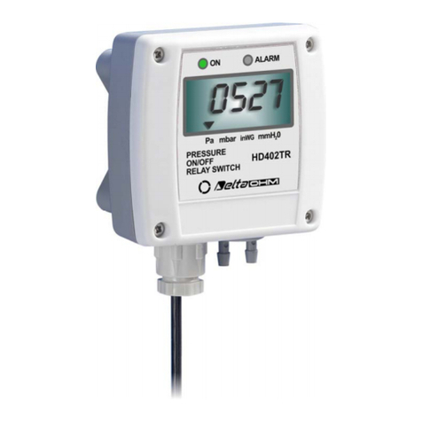
Delta OHM HD402TR Series User manual
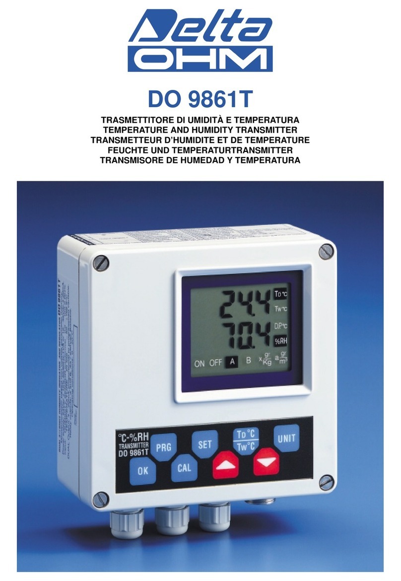
Delta OHM
Delta OHM DO 9861T User manual
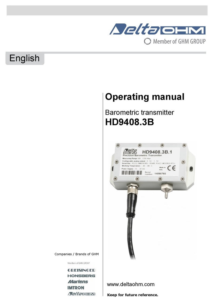
Delta OHM
Delta OHM HD9408.3B User manual
Delta OHM
Delta OHM HD40.2 User manual
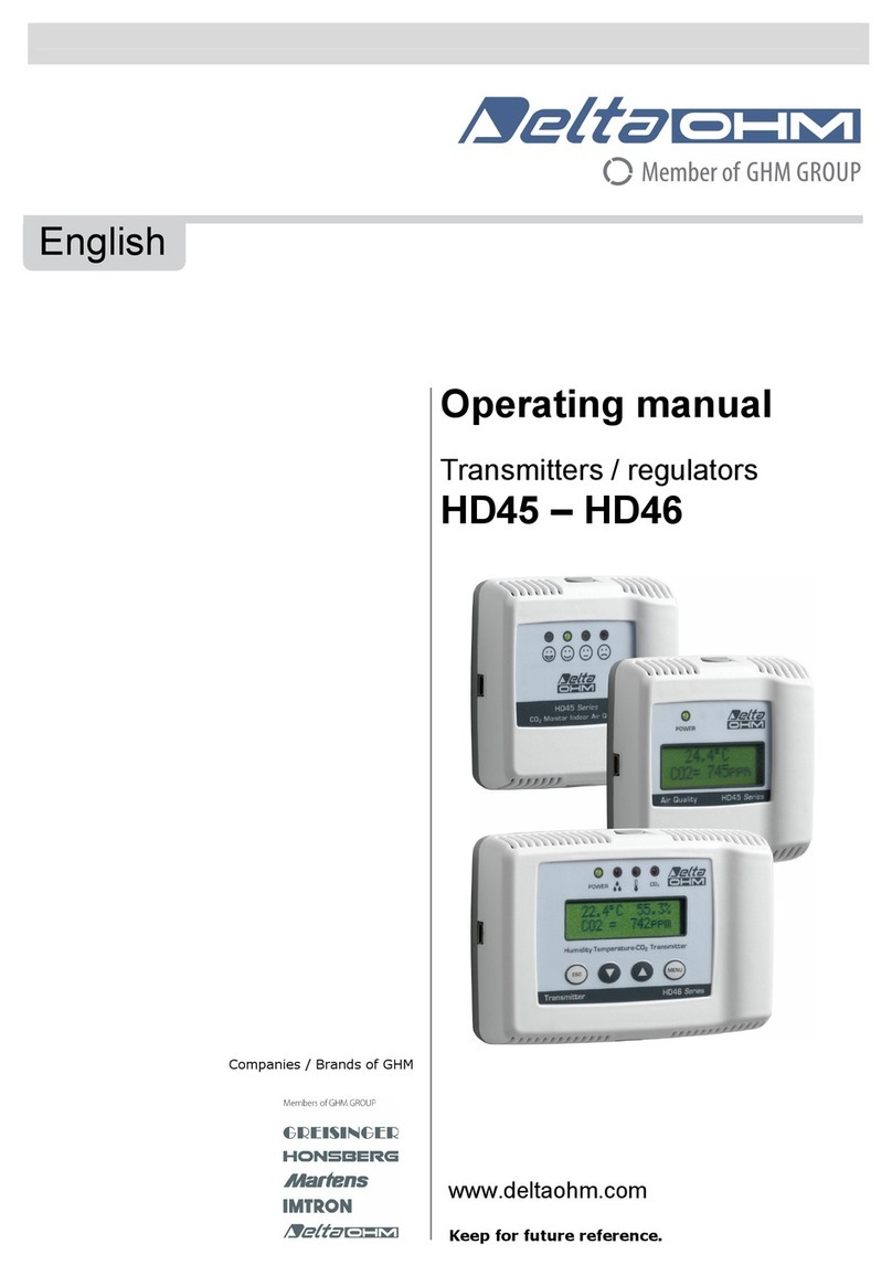
Delta OHM
Delta OHM HD45 17V User manual
