Melbourne MTC-49407 User manual

1
LOW ANGLE BLOCK PLANE
Owner’s Manual
V3/22
Record the invoice number and date of purchase in your manual for
future reference.
Invoice Number: ................................................................
Date of Purchase: .............................................................

2
Sole length 165mm
Solo Width 43mm
Weight 750g
Blade Bed Angle 12°
Blade Steel M2 HSS
Blade Width 35mm
Blade Thickness 3.4mm
Included Blade 25° Bevel Angle
Block Plane
Specifications: MTC-49407
Product
Code
Bevel
Angle
Effective
Cutting Angle
MTC-49506 25° 37°
MTC-49513 38° 50°
MTC-49520 50° 62°
Additional Blades

3
CONTENTS
Introduction 4
Melbourne Tool Company 4
Section 1: Safety 6
General Safety Rules 6
Section 2: Component Diagram 7
Section 3: Operation 8
First Use 8
Sharpening Blade 8
Setting the Blade 9
Mouth Adjustment 10
Bevel Angles & Grain Direction 11
User Guide 11
Section 4: Maintenance 13
Section 5: Troubleshooting 14
Ensure the blade is sharp 14
Tear-out 14
The plane leaves tracks on a board’s surface. 14
The plane is hard to push 14
Section 6: Warranty 15
Melbourne Tool Company Warranty Statement 15
Disclaimer 16
Manual Accuracy 16
Technical Support 16

4
INTRODUCTION
Melbourne Tool Company
The most human thing you can do is make things.
And there is no more natural way to-do this than work with wood.
Yet wood working is not without its challenges, it takes focus and
discipline to learn the craft. Good makers stick at it and work hard
because nothing else really matters.
Woodworking also requires great tools.
Tools that are genuine, accurate and accessible. Knowing this led to the
creation of the Melbourne Tool Company. Designed and developed in
Melbourne Australia, for all you passionate woodworkers out there.
Low-Angle Block Plane
Your MTC Low Angle Block Plane is the essential tool in your woodworking
kit. The three blade types available makes everything from trimming tricky
end grain through to chamfering and smoothing figured timbers a breeze.
Comfortable to hold with one hand or two, you will be reaching for your
MTC block plane just about every time you’re at the bench.
Welcome to the MTC family.

5

6
SECTION 1:
SAFETY
General Safety Rules
For your own safety, please read and understand
this instruction manual before installing and
operating the tool.
Owner’s Manual:
Read and understand this owner’s manual before using the tool
Handle With Care:
Hand tools include sharp blades that will cause serious injury if handled
improperly. Dropping the tool will likely cause damage to the tool and
anything it lands on, including but not limited to your toes.
Keep the Tool Sharp:
A blunt tool will require excessive force to be used, which greatly
increases the chance of injury.
Awkward Positions:
Keep proper footing and balance at all times when using the tool.
Arrange the workpiece so that you can bring the tool to the work in a
comfortable manner.
Experiencing Difficulties?
If at any time you experience difficulties in performing the intended
operation, stop using the tool and consult this owner’s manual. For further
retailer from which you purchased the tool.

7
Diagram
SECTION 2:
COMPONENT DIAGRAM
1. Toe
2. Front Knob
3. Mouth Adjustment Lever
4. Mouth Adjustable
5. Blade
6. Blade Bed
7. Sole
8. Lever Cap
9. Lever Cap Screw
10. Lever Cap Wheel
11. Depth & Lateral Adjustment
Wheel
12. Adjuster Pin
1.
2.
5.
8.
10.
11.
12.
3.
4.
6.
7.
9.

8
First Use
Your plane ships with a coating of rust-inhibiting oil to ensure it arrives to
you in good condition, but this must be removed prior to use.
Disassemble the plane by loosening the lever cap wheel and removing
the lever cap, blade, and adjuster assembly, taking care with the sharp
edge of the blade.
Unscrew the Front Handle completely, and remove the Toe and Mouth
Adjuster.
Using a clean rag, wipe all components to remove all but the lightest
coating of oil.
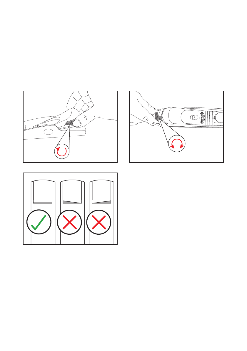
Reassemble the plane, noting the correct orientation of the blade (bevel
facing up) and taking care not to damage the edge.
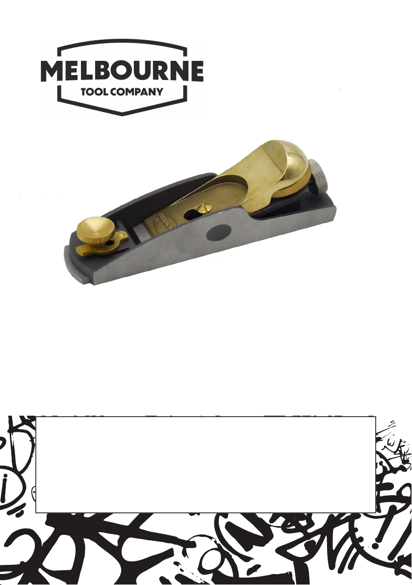
Do not over-tighten the lever cap wheel – it only needs a quarter-turn or
so once the slack is taken out.
SECTION 3:
OPERATION
Sharpening the Blade
The blade is ground to the correct angle but will require sharpening
before use.
Periodically check the condition of the blade and resharpen as required
– A sharp blade is the single biggest factor in enjoying the use of your
plane, and the quality of the surface it produces.
When replacing the blade, check the bed is free from wood shavings and
any build-up of wax or oil.

9
The Depth & Lateral Adjustment Wheel controls both the projection of the
blade below the sole and the lateral angle of the blade.
Turning the wheel clockwise advances the blade, while turning it
anticlockwise retracts it. Pushing the wheel to the left skews the blade to
the right, and vice versa.
Setting the blade
1. Loosen the lever cap wheel just enough so that adjustments can be
made without excessive force.
2. Open the mouth of the plane to avoid advancing the blade into the
mouth.
3. Place the plane on a flat timber surface and advance the blade until it
just touches the surface.
4. Holding the plane upside-down, check the blade is parallel to the
mouth opening.
5. Tighten the lever cap wheel (do not over-tighten) and take a test cut.
Repeat the procedure to advance the blade as necessary.
Depth & Lateral Adjustment
Blade Mouth Adjustment
Tighten or Loosen

10
Mouth Adjustment
The Toe pushes down on the wood fibers in front of the blade, preventing
the wood from splitting and tearing out ahead of the cut.
To maximise the effect of the Toe, set it so that the mouth opening is as
small as possible while still allowing a shaving to escape. The deeper the
cut you are taking, the thicker the shaving will be, and so the wider the
mouth will need to be.
To adjust the mouth opening, loosen the front handle and swing the Mouth
Adjustment Lever right or left to move the Toe forward or backward. Take
care not to move the Toe into the blade. Tighten the front handle to lock
the position of the Toe.
Mouth Adjustment
Adjusting the front handle. Swinging the mouth lever.

11
Bevel Angles & Grain Direction
The MTC-49407 has a bed angle of 12° and comes standard with a blade
sharpened to 25°, giving a cutting angle of 37°. This angle is well suited
for end-grain work and jointing tasks in softwood and some hardwoods
where it is possible to plane with the grain
When cutting end grain, the plane should be set for a very light cut.
Beware of ‘break-out’ on the rear edge of the workpiece, where the edge
grain breaks away as the blade exits the cut. You can prevent this by
clamping a piece of scrap to the rear edge to support the fibers, or by
stopping the cut before the end of the board and beginning a new cut
from the opposite direction.
End grain 25° Bevel Angle
25°Bevel
37°Cutting
Angle
12°Bed Angle
12°Bed Angle
12°Bed Angle
50°Bevel
62°Cutting
Angle
38°Bevel
50°Cutting
Angle
Planing end grain with the 25°blade

12
Timbers with birdseye, interlocked grain, fiddleback or other kinds of
reversing grain will be more easily smoothed with a 50° blade, yielding
an overall cutting angle of 62°.
While you can change the bevel angle of a single blade, this is very
labour-intensive, especially when going from a higher to a lower angle.
Additional blades are available from Melbourne Tool Company that come
pre-ground to the angles mentioned above. Having multiple blades that
can be swapped out allows the user to change cutting angle quickly and
will make the MTC-49407 a very versatile tool.
Smoothing jobs are often better handled with a higher cutting angle. The
38° blade gives an overall cutting angle of 50°, an excellent general-
purpose smoothing angle. The 38° blade is also ideal when traversing
(planing panels across the grain).
Planing with grain38° Bevel Angle
50° Bevel Angle Figured Grain
25°Bevel
37°Cutting
Angle
12°Bed Angle
12°Bed Angle
12°Bed Angle
50°Bevel
62°Cutting
Angle
38°Bevel
50°Cutting
Angle
25°Bevel
37°Cutting
Angle
12°Bed Angle
12°Bed Angle
12°Bed Angle
50°Bevel
62°Cutting
Angle
38°Bevel
50°Cutting
Angle
Smoothing using the 38° blade
Planing figured timber using the 50° blade

13
User Guide
Angle Primary Purpose Product Code
25°End grain MTC-49506
38°Bevel smoothing MTC-49513
50°Smoothing figured timber MTC-49520

14
Maintenance
• After each use, disassemble the plane and clean off accumulated dirt,
grease, resin and rust, especially from the threads and blade bed. An
old toothbrush is ideal for this. Ensure your flatmate is finished with it
first.
• If the plane is stored in damp or humid conditions, or when overnight
temperatures drop significantly, the plane should be stored wrapped in
cloth or in a plane sack.
• A light layer of paste wax with rust inhibiting ingredients is ideal for
protecting the raw metal parts of the plane. Alternatively, a light machine
oil can be applied. In either case ensure that any excess is removed,
leaving only a very light coating on the tool.
• It is a good idea to also wipe off finger marks after use to minimise
the chance of surface rust.
SECTION 4:
MAINTENANCE

15
SECTION 5:
TROUBLESHOOTING
Ensure the blade is sharp
Tear-out
The plane leaves tracks on a board’s surface.
The plane is hard to push
The first step of any troubleshooting is to ensure that blade is sharp. If
sharpening the blade does not resolve the issue, please see below for
further suggestions.
This usually occurs when the blade isn’t level, or there’s a nick in the
blade.
• Align cutting edge of blade with mouth opening using lateral
adjustment lever
• Check blade for damage and sharpen to remove any nicks.
Retract the blade slightly to take a lighter cut.
• Retract blade to take a lighter cut
• Lubricate the sole with light oil or an old candle
• Note that the higher angle 50* blade will require greater pushing
force than the lower angle 25* blade.
Tear-out occurs when the wood splits ahead of the blade. The blade then
acts as a wedge and removes chunks rather than shavings.
There are three main causes of tear-out:
1. The mouth opening is too large. Adjust the mouth to be as tight as
possible whilst allowing the evacuation of the shaving.
2. The grain direction is incorrect. Ensure that the plane is used with the
grain.
3. The cutting angle is too acute. Try a blade with a higher bevel angle.

16
Section 6:
WARRANTY & SUPPORT
Melbourne Tool Company Warranty Statement
The metal parts of this Plane carry a Lifetime Warranty against manufacturing
defects. The warranty does not cover modifications, willful misuse, accidental
damage, or damage arising from the owner’s failure to reasonably maintain
the product.
Non-metal parts carry a two-year warranty against defects. The warranty
does not cover modifications, willful misuse, accidental damage, or damage
arising from the owner’s failure to reasonably maintain the product.
If your Melbourne Tool Company product has a warrant-able fault, please
contact the retailer that it was purchased from.
Our goods come with guarantees that cannot be excluded under the
Australian Consumer Law. You are entitled to a replacement or refund for a
major failure and compensation for any other reasonably foreseeable loss
or damage. You are also entitled to have the goods repaired or replaced if
the goods fail to be of acceptable quality and the failure does not amount
to a major failure.

17
Disclaimer
Customers should ensure that they take all reasonable safety precautions
when operating MTC products. MTC will not be held liable to you in respect
of any personal injury (including without limitation serious injury or death)
that you may suffer or sustain directly or indirectly as a result of the use of
products sold by us. Nor will we be liable to you in respect of any other
losses arising as a result of any such personal injury.
Nothing in this disclaimer shall: limit or exclude our liability for death or
personal injury resulting from negligence; limit or exclude our liability for
fraud or fraudulent misrepresentation; limit any of our liabilities in any way
that is not permitted under applicable law; or exclude any of our liabilities
that may not be excluded under applicable law.
Technical Support
If you have a question about your MTC product that isn’t covered in
Manual Accuracy
We have made every effort to be exact with the specifications,
instructions, drawings, and photographs in this manual. Our policy
of continuous improvement can sometimes mean that sometimes the
machine you receive is slightly different to that shown in the manual.
If you find this to be the case, and the difference between the manual
and the product leaves you confused or unsure about something, check
the retailer’s website for an updated version. Alternatively, you can

18

19
Notes:

20
Notes:
Table of contents