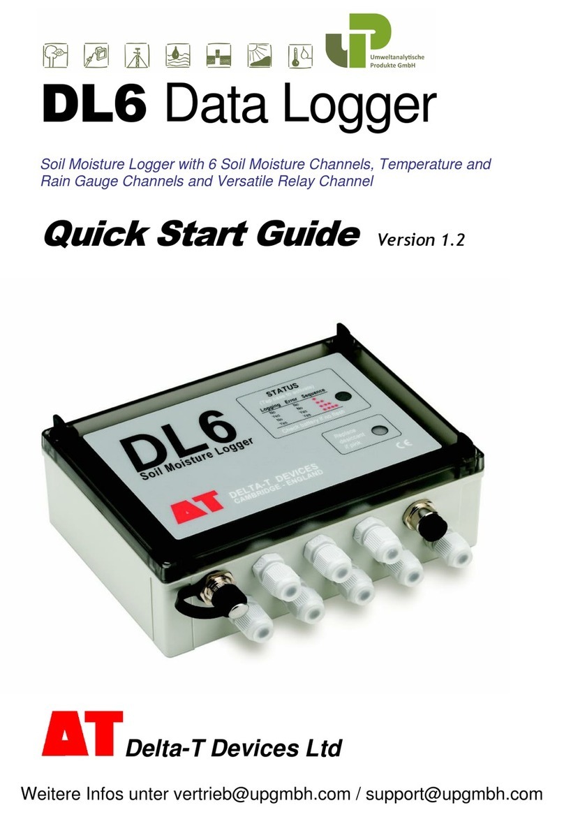
Delta-T Devices DL6 User manual

User Manual
Soil Moisture
Logger Type DL6
DL6-UM-1.3
Delta-T Devices Ltd

Notices
Copyright
All rights reserved. Under the copyright laws, this manual may not be
copied, in whole or in part, without the written consent of Delta-T Devices
Ltd. Under the law, copying includes translation into another language.
Copyright © 2004 Delta-T Devices Limited
Trademarks
Windows is a registered trademark of Microsoft Corporation.
All other trademarks are acknowledged. Some names referred to are
registered trademarks.
Delta-T Devices Ltd reserves the right to change the designs and
specifications of its products at any time without prior notice.
CE conformity
See page 35
Author
Nick Webb
Versions
User Manual Version: 1.3 Nov 04
It is intended for use with the following:
Windows PC DL6 Control Panel software version 1.50,
Pocket DeltaLINK software version 1.50
DL6 logger serial numbers DL6 03-06 or later.
These latest versions add support for PR2 Profile Probes and the Pocket
PC.
Delta-T Devices Ltd Tel: +44 (0)1638 742922
128 Low Road, Burwell Fax: +44 (0)1638 743155
U.K. www: http://www.delta-t.co.uk

Contents
INTRODUCTION ............................................................4
HARDWARE INSTALLATION .......................................5
SOFTWARE .................................................................11
SPECIFICATIONS .......................................................28
MAINTENANCE, TROUBLESHOOTING, STORAGE .30
WARRANTY AND SERVICE .......................................33
INDEX...........................................................................36
DL6 User Manual v 1.3 Contents
z
3

Introduction
This manual describes how to use the DL6 Soil Moisture Logger.
What it measures
Up to six soil moisture sensors, plus one temperature and one rain gauge
reading can be recorded on 8 channels. Up to 16000 sets of readings can
be stored.
It can read various combinations of soil moisture sensors,
e.g. six ThetaProbe sensors (types ML1,ML2 & ML2x)
or one 6 channel Profile Probe (type PR2 or PR1)
or one 4 channel Profile Probe plus two ML2 sensors.
It can read one 2k thermistor temperature sensor and one tipping bucket
type rain gauge.
What it is used for
It can record soil moisture over a few hours, days or months.
It can signal low or high soil moisture or temperature via an alarm output.
It can be used to monitor the effectiveness of irrigation or rainfall.
A fast logging mode is provided to capture soil moisture changes and soil
wetting fronts following rainfall events.
Advantages
Easy to use PC and Pocket PC software.
Cost effective, optimised to work with Delta-T soil moisture sensors and
designed specifically to help soil moisture monitoring.
Weatherproof socket for PR2 Profile Probe cables simplifies connection.
What’s New?
This version of the DL6 adds support for PR2 Profile Probes and also
includes Pocket PC to simplify programming, inspection and data collection
in the field.
See also: Versions on page 2.
4
z
Introduction DL6 User Manual v 1.3

Hardware Installation
Unpacking
Your should have the following:
Part Sales Code Description
Logger DL6 Soil moisture
Logger with
battery, software,
RS-232 cable and
this manual
DL6 Software DL6-SW1 Windows software
on CD
Serial Cable DL6-RS232 4-way IP67
connector to 9 pin
D connector.
Length 2m.
Your consignment may also have some or all of the following
Mounting Kit DL6-
MKT1
1m stainless steel
post, mounting plate,
bolts, nuts, screws,
cable ties
Spares Kit DL6-SP Includes: fuse,
desiccant, battery
holder, cable glands,
bungs and O rings
Spare
alkaline
batteries
DL6-BAT 6 x AA alkaline cells *
Spare Lithium
batteries
BL6-ELB 6 x AA lithium cells *
* see Batteries on page 30.
DL6 User Manual v 1.3 Hardware Installation
z
5

Flashing LED
Tap the Logger - the LED should flash.
It will not flash or communicate if the battery is low or if a program is not
installed.
Logging Error Sequence Meaning
No No The logger is not logging.
There is no error.
Yes No The logger is logging.
There is no error.
No Yes The logger is not logging.
There is an error.
Yes Yes The logger is logging.
There is an error.
Note: The logger also flashes when it resets.
See: Reset the Logger on page 32.
6
z
Hardware Installation DL6 User Manual v 1.3

DL6 User Manual v 1.3DL6 User Manual v 1.3 Hardware Installation
z
7Hardware Installation
z
7
Layout

Connecting sensors
Warning: If using screw terminals strip 1cm of bare wire - less than this
risks making a poor contact.
Profile Probes
Profile Probe PR2/4 and PR2/6: Use the connector provided.
Do not connect any other sensors to channels 1-4 or 1-6 respectively.
Profile Probe PR1/6: Connect to channel 1, PROFILE and POWER
terminals according to the colours printed beside the terminals. Do not
connect any other soil moisture or voltage sensors to channels 1 to 6.
Profile Probe PR1/4: Connect to channel 1, PROFILE and POWER
terminals according to the colours printed beside the terminals. Connect
additional soil moisture or voltage sensors to channels 5 and 6 if required.
Do not connect other sensors to channels 1 to 4.
8
z
Hardware Installation DL6 User Manual v 1.3

ThetaProbe ML2, ML2x & ML1
Connect up to 6 ML2s to channels 1 to 6 and POWER terminals according
to the colours printed beside the terminals.
The diagram shows one ML2 connected to channel 1.
Other voltage sensors
Connect to channels 1 to 6 and POWER terminals as follows:
IN+ Signal HI
IN- Signal LO (see note *)
/// Braid or screen, if required
V+ Power V+, if required
0V Power 0V, if required
Note*: To avoid ground loops, connect Signal LO to /// if and only if the
sensor output is electrically isolated from both /// and OV.
DL6 User Manual v 1.3 Hardware Installation
z
9

2k thermistor probes (e.g. ST1)
Connect to channel 7 IN+ and IN-. Connect any braid
or screen to the /// terminal if required
Resistance sensor
Connect to channel 7 IN+ and IN-. Connect any braid
or screen to the /// terminal if required.
Rain gauge (e.g. RG2)
Connect to channel 8 IN+ and IN- terminals. Connect
any braid or screen to the /// terminal (channel 7) if
required.
Pulse output sensor
Connect to channel 8 IN+ and IN-. Connect any braid
or screen to the /// terminal (channel 7) if required.
Alarm output
Connect to channel 9 HI and LO
Note: The alarm output switches only when the logger reads an analogue
sensor e.g. soil moisture or temperature.
10
z
DL6 User Manual v 1.3

Software
Software Installation
Items required
To operate the logger from your PC you need the following:
1. A PC running one of the following:
Windows 95 + Internet Explorer 5.0 or later,
Windows NT 4.0 + SP6 + Internet Explorer 5.0 or later,
Windows 98,
Windows ME,
Windows 2000, or
Windows XP
2. Microsoft Excel 97 or later is required for the Dataset Import Wizard.
3. One free 9-way RS232 serial port.
4. CD ROM drive for installation.
5. At least 10 MB of hard disk space.
6. Logger PC RS232 cable: type DL6-RS232.
7. DL6-SW1 software distribution disk.
Installing DL6 Software
Insert the distribution disk in your CD ROM drive.
If Autorun is enabled on your PC your CD will automatically start to lead you
through the installation process.
If Autorun is not enabled you will need to start the install program as follows:
1. From the Start menu select Settings, Control Panel.
2. In Control Panel, select Add/Remove Programs.
3. In Add/Remove Programs, Properties, select the Install/Uninstall
tab.
4. Click Install, and follow the on-screen instructions.
Setup installs the following:
DL6 Control Panel
DL6 Firmware Upgrade program
Install Data Import Wizard
DL6 User manual
DL6 User Manual v 1.3 Software
z
11

Check DL6 to PC Communications
Connect the DL6 to your PC with the DL6-RS232 cable.
Select Start, Programs, DL6 Logger, DL6 Control Panel.
The first time you do this a
Connection Properties
dialog appears.
Accept the default serial
Port or change it to suit your
PC, and click OK.
If the logger can
communicate, then the DL6
Control Panel will be
displayed, populating the Logger tab with information about the logger.
If you see something like this you have successfully established
communication with the logger!
Note the following:
Start: used to start (and stop) logging
Set Clock: used to synchronise the logger clock with the PC.
Dataset Full By: estimates the date and time when the logger will be full.
Refresh: contacts the logger and refreshes the information on this tab.
Details: displays warnings and error messages recorded while logging.
Can’t communicate? See Troubleshooting
12
z
Software DL6 User Manual v 1.3

Program the DL6
1. Select Start,
Programs, DL6 Logger,
DL6 Control Panel.
2. Select the Program
tab on the DL6 Control
Panel.
3. Select Change to edit
the program.
4. Right click on channel 1 and select a
sensor from the list -
e.g. Profile Probe PR2/4.
Observe that channels 1 to 4 are
automatically populated with
parameters when a PR1/4 is
selected.
If using 2 ThetaProbes, be sure to
name each with a different label in
the program.
5. Enter a Program Name
6. Enter a Recording Rate.
7. Double-click on each sensor
channel to inspect and edit sensor
parameters
See also: Channel Properties on p.18
Upload Program to
Logger
Select Apply to send the program to
the logger.
Save Program
From the Program tab select the
File,Save command to save the
program to disk.
Start/Stop Logging
In the Logger tab toggle the Start/Stop button.
DL6 User Manual v 1.3 Software
z
13

Alarm Channel
Channel 9 is a switch which may be
used to signal when the soil moisture or
temperature meets a particular condition.
Expand the Program tab window.
Click on Change to enable
program editing.
Double-click on the row for
channel 9 in the Alarm Output
box to open the Alarm Channel
Properties dialog.
Label: Enter a useful label.
Controlled by: Select one sensor
from the drop-down box.
Condition: options are: Less
than or Greater than.
Threshold: Enter a numerical value.
Select OK. The alarm condition parameters
should appear in the Program tab.
Note once the condition is met it stays in that state until the next logging
interval, when it is re-assessed.
For instance: if you are logging once per hour the relay will switch on for at
least one hour.
For more details select DL6 Control Panel, Help.
14
z
Software DL6 User Manual v 1.3

Dual Recording Rate
Accelerated recording can be started when the rate of rainfall exceeds a
given threshold. This lets your record occasional fast events – such as the
penetration into the soil of a wetting front.
Expand the Program tab window, click on Change to enable program
editing.
Check the Dual Recording Rate box to enable dual rate recording.
Two conditions may be set for the duration of the accelerated logging
1. Continue for a specified period of time beyond the last reading above
the rate of rainfall threshold ( e.g. in mm/hr)
2. And also wait until the rate of change of all soil moisture sensor
readings fall below a given rate in the selected moisture units
(e.g. in m3.m-3/hr).
When rainfall rate rises above: Enter the rate of rainfall above which the
faster rate of recording should start e.g. 2 mm/hr.
For your guidance:
A low rate (0.1 mm/hour) will activate fast recording for nearly all rainfall
events.
A medium rate (1mm/hr) will activate fast recording only for medium and
heavy rain events.
A high rate (5mm/hr) will activate fast recording only for very heavy rain
events.
DL6 User Manual v 1.3 Software
z
15

Start recording soil moisture every: Enter the faster rate of recording
readings. This should be an integer sub-multiple of the normal recording
rate e.g. 5 minutes (for the 1 hour normal rate shown above).
Continue for at least: Enter how long you want accelerated recording to
last e.g. 2 hours.
Note this time interval will only start after the rate of rainfall falls below the
threshold again, (not from the start of fast recording.)
And until soil moisture changes fall below: Use this if you wish to keep
recording at the faster rate beyond the set time delay, if soil moisture
readings from any sensor are still changing faster than normal.
Enter the rate here - e.g. 0.05 m3.m-3/hr
This is the rate of change for any of the soil moisture sensors.
Fast logging will continue until all soil moisture sensors fall below this rate
(provided that the time-delay in not still in effect).
For your guidance:
0.05 m3.m-3/hour is a very high rate of change,
0.005 m3.m-3/hour is a medium rate of change,
0.0005 m3.m-3/hour is slow.
You must enter a rate in the box.
If you enter 0 fast recording will never stop.
If you do not want this option to take effect use a very high rate of change.
Note these guidance values are not absolute. They depend on your local
soil or weather conditions and experimental needs.
Note: Every tip of the rain gauge is temporarily stored with a time stamp of
when it occurred.
At every tip, the DL6 looks at the time stamp of the previous tip, and
calculates the rate.
This refreshes the "continue for X hours" condition, every time the rate is
above the threshold value.
16
z
Software DL6 User Manual v 1.3

Example of accelerated logging
soil moisture
0
0.1
0.2
0.3
0.4
0.5
0.6
14
16
18
20
22
00
02
04
06
08
10
12
14
Time (hours)
soil moisture (m3.m-3)
rainfall
0
2
4
6
8
14
16
18
20
22
00
02
04
06
08
10
12
14
Time (hours)
mm
1) When rainfall
rate rises above
2 mm/hr
3) Continue for
at least 3 hours
0.05
0.005
0.0005
4) And unitil all soil moisture
changes fall below
+/- 0.05 m3.m-3%/hr
The slope exceeded this for
j
ust~1½ hrs here.
2) Start
recording every
10 minutes
100 mm
200 mm
300 mm
400 mm
DL6 User Manual v 1.3 Software
z
17

Channel Properties
Each row of the Program tab in the DL6 Control Panel lists the channel
properties, these define how raw data from a sensor is to be converted into
engineering units.
In Program tab, if necessary, click on Change to enable program editing.
Double click on any of channels 1 to 6 to display the Soil Moisture
(Voltage) Channel Properties dialog.
This example shows the channel properties for a PR1/4 Probe.
Soil Properties: Two linear
coefficients a0 and a1 are used
to convert measured soil
permittivity* into moisture
content. This conversion
depends on the soil type.
Two standard Soil Types are
provided: Mineral or Organic
soils.
*Footnote: Our soil moisture sensors
actually measure the square root of
permittivity, converting that to
moisture by the use of these two
coefficients.
About a0 and a1.
These parameters are used with the selected sensor-specific Linearisation
Table in the DL6, to convert the sensor mV output into soil moisture
readings. They are a convenient and efficient way of describing the
calibration curves for different soil types without the memory overhead
required for a unique table for every different soil.
For optimum accuracy you should obtain soil-specific calibration coefficients
for your soil as described in your sensor user manual.
You may skip this step by choosing the Mineral or Organic Soil Types. You
lose some accuracy but it is easier. Their soil coefficients are permanently
installed in the DL6.
Data storage- Maximum, Minimum and Resolution.
These can be used to scale charts, select a suitable number of decimal
places, and control the amount of memory used. The default values are
optimised for the standard sensors.
18
z
Software DL6 User Manual v 1.3

Verifying Sensor Operation
In the Sensors tab of the DL6 Control Panel select Read now,
The readings will continually refresh a scrolling graph.
DL6 User Manual v 1.3 Software
z
19

Datasets: retrieving, viewing, saving
From the DL6 Control Panel Select the Dataset tab.
Select Refresh to retrieve and view the dataset.
Select View, Chart or View, Table to view it as a graph or table
Select File, Save to save the dataset as a “.dt6” type data file.
Chart and Table views of the data.
See also: Dataset Import Wizard on page21.
To save data as an ASCII text file, first save it as a dataset file. This will
activate the Dataset Viewer. From the Dataset Viewer use the Save As
command (File menu) to save the dataset as a comma-, tab or space-
separated file, for importing into other programs.
20
z
Software DL6 User Manual v 1.3
Other manuals for DL6
1
Table of contents
Other Delta-T Devices Data Logger manuals
