Delta-T SLM4 User manual

8VHU0DQXDOIRUWKH
6HOI/HYHOOLQJ0RXQW
W\SH 6/0
'HOWD7'HYLFHV/WG
SLM4-UM-1.0

1RWLFHV
&RS\ULJKW
All rights reserved. Under the copyright laws, this manual may not be
copied, in whole or in part, without the written consent of Delta-T Devices
Ltd. Under the law, copying includes translation into another language.
Copyright © 2000, 2003 Delta-T Devices Limited
'HVLJQFKDQJHV
Delta-T Devices Ltd reserves the right to change the designs and
specifications of its products at any time without prior notice.
$XWKRUV
John Wood, Edmund Potter.
8VHU0DQXDO9HUVLRQ -DQ
'HOWD7'HYLFHV/WG
7HO
/RZ5RDG%XUZHOO
)D[
&$0%5,'*(&%(-
HPDLOsales@delta-t.co.uk
8.
ZZZ http://www.delta-t.co.uk

6/08VHU0DQXDOY &RQWHQWV z
&RQWHQWV
6HOI/HYHOOLQJ0RXQW7\SH6/0
)HDWXUHV
$VVHPEO\,QVWUXFWLRQV
,QVWUXFWLRQVIRU8VH
To operate 10
Image alignment in HemiView 10
8VLQJWKH1LNRQ&RROSL[&DPHUD
7DNLQJ+HPLSKRWRV
Image size and compression 11
Camera settings 11
Exposure 12
Taking the Picture 13
'RZQORDGLQJLPDJHVWRD3&
:DUUDQW\DQG6HUYLFH
7HUPVDQG&RQGLWLRQVRI6DOH
6HUYLFHDQG6SDUHV
7HFKQLFDO6XSSRUW
Contact details 15

z&RQWHQWV 6/08VHU0DQXDOY
6HOI/HYHOOLQJ0RXQW7\SH6/0
)HDWXUHV
The self levelling mount (SLM4) is intended for use with either a tripod or
a monopod, and is designed to help keep a camera and fisheye lens
aligned to the horizon and North. This is necessary for taking hemiphots
for use with Delta-T’s HemiView canopy analysis software.
The SLM4 is designed for use with the Nikon Coolpix 4500 digital camera
with hemispherical lens attachment.
For ease of use, the mount is equipped with the following features:-
·Bubble level with adjustable levelling weights
·Compass for North/South alignment, viewable from above or below
·Markers used to align Hemiphots in HemiView, illuminated by
camera flashgun
·Lens protective cover
6/08VHU0DQXDOY &RQWHQWV z
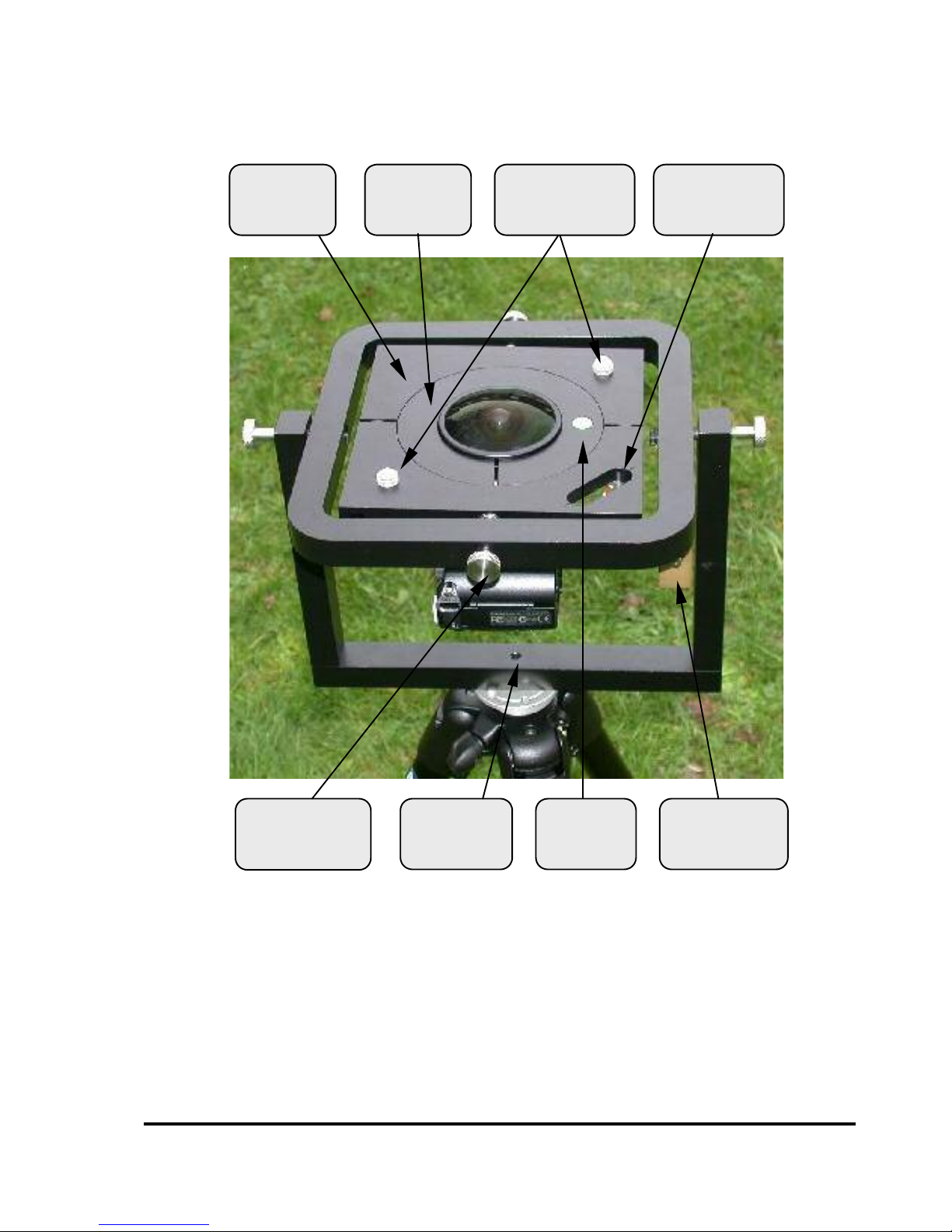
Fig 1. SLM4 with lens cover removed
7ULSRG
VRFNHW
&RPSDVV
$OLJQPHQW
PDUNHUV
,QQHUSLYRW
VFUHZ
*LPEDO
SODWH
%XEEOH
OHYHO
%DODQFH
ZHLJKW
&ROODU

z&RQWHQWV 6/08VHU0DQXDOY
$VVHPEO\,QVWUXFWLRQV
·Fix the SLM4 to a tripod for stability, using tripod socket in its base
(Fig 1).
·Fit the lens into the collar. Tighten the clamping screw using the
4mm hex driver supplied (Fig. 2). (If the lens has been supplied as
part of a HemiView system it will already have been fitted to the
collar).
·Undo the inner pivot screws a few turns (Fig. 1). 'RQRW unscrew
them completely.
·Tip the gimbal plate slightly (Fig 4) and slacken both the screws
which clamp it together.
·Fit the lens and collar assembly into the gimbal plate. 'RQRWtighten
it yet.
·Screw the camera onto the threaded end of the lens, by holding the
camera steady and rotating the lens and collar (Fig 3).
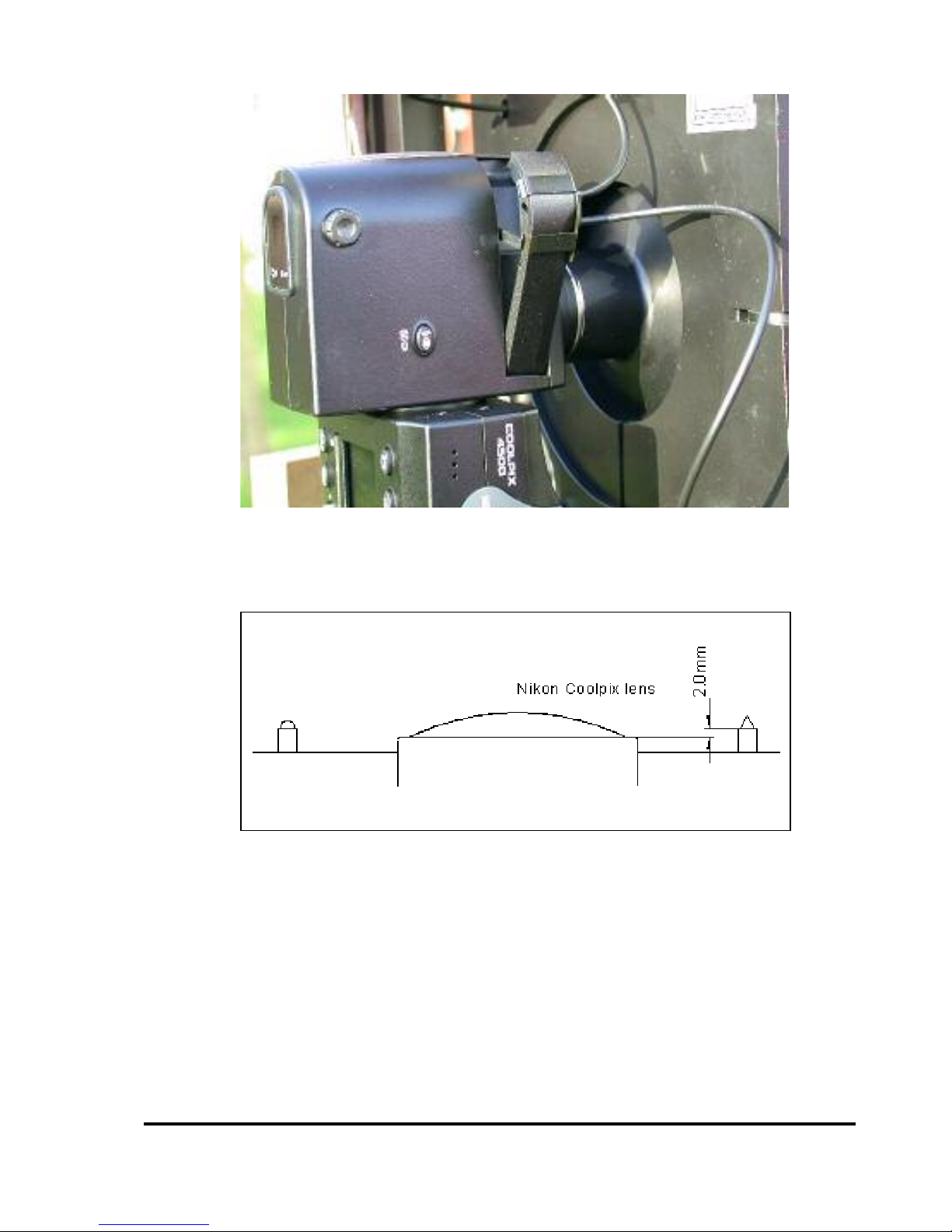
·Check that the lens edge is 2mm below the alignment marker
shoulders (Fig 7), and the camera is positioned as in Fig 5.
·Clamp the assembly by tipping the gimbal plate and tightening the
two clamping screws (Fig 4).
·Tighten the inner pivot screws (Fig 1) until the assembly swings
freely but comes to rest quickly. 'RQRWovertighten the pivot screws.
·Fit the alignment marker clip onto the camera flash unit (Fig. 6). The
flash unit will pop up if the camera is set to ‘anytime flash’ and you
press the shutter release halfway. 'RQRWtry to force it up.
·Move the balance weights so that the bubble is within the central
circle of the bubble level. Use the large weights for coarse
adjustment, and the small weights for the final fine adjustment.
·Check the mount is level whenever you move the camera, or change
battery or flashcard.

6/08VHU0DQXDOY &RQWHQWV z
Fig. 2 Fitting the lens to the collar
Fig. 3 Fitting the camera to the lens

z&RQWHQWV 6/08VHU0DQXDOY
Fig. 4 Clamping the collar to the gimbal plate
Fig. 5 Orientation of camera
6/08VHU0DQXDOY &RQWHQWV z
Fig. 6 Fitting the alignment marker clip to the flash unit
Fig. 7 Checking the lens alignment

z&RQWHQWV 6/08VHU0DQXDOY
,QVWUXFWLRQVIRU8VH
7RRSHUDWH
Remove the lens cover.
Level the mount using the balance weights and bubble level.
Rotate the mount so that the red end of the compass needle is between
the marks on the compass housing. If you are using the mount above
your head, make sure you know roughly which way North is, as the two
ends of the needle look the same from below.
Select an appropriate exposure setting.
Set the camera self-timer, press the shutter release and put the mount at
the required height. Keep the mount as level as possible, otherwise parts
of the mount may be visible in the picture.
Replace the lens cover to protect the lens from dirt or damage.
,PDJHDOLJQPHQWLQ+HPL9LHZ
Align the horizon circle to the shoulders of the two alignment markers,
with the pointed marker at the magnetic north point, as shown below.

6/08VHU0DQXDOY &RQWHQWV z
8VLQJWKH1LNRQ&RROSL[&DPHUD
7DNLQJ+HPLSKRWRV
The Coolpix 4500 is a very capable camera, and the user has a lot of
control over the settings. This does mean that getting the right settings
can be complicated. It is well worth taking some time to learn how the
camera works before using it in the field. The following notes will point
you towards the appropriate sections of the camera manual. Page
numbers refer to the English version of the manual supplied with the
camera.
,PDJHVL]HDQGFRPSUHVVLRQ
There is a trade-off between image quality and the number of images you
can store on a memory card. Keep image size at 2272 x 1704 for
maximum spatial resolution. We recommend using Fine image quality.
This will give you approximately 8 images on a 16MB card, 33 on a 64MB
card. Normal image quality may be adequate for many canopies,
particularly broad-leaved canopies, and will double the number of images
you can store. Do a trial comparison on your site to see if the image
quality makes any significant difference. See p 101.
&DPHUDVHWWLQJV
The following Shooting Menu settings should be used (see p 82):
·White balance Auto
·Metering Matrix
·Image Adjustment Normal
·Saturation Normal
·Image sharpening Normal
·Lens None (Do not set this to “fisheye”, as this
gives you a very restricted range of settings)
·Focus Auto, Single AF
·Zoom Digital Tele Off, Startup Wide
·Speedlight Int & Ext Active
The flash should be set to “Anytime Flash” (using the flash button, p 64).
These settings can be saved in one of the user settings so they can be
easily restored, see p 104.

z&RQWHQWV 6/08VHU0DQXDOY
([SRVXUH
Getting the exposure right can have a significant effect on how easy it is
to classify your image in HemiView, and on the accuracy of your
calculations. Your aim is to have areas of sky at the top end of the
brightness range, and areas of canopy at the lower end. You can check
this on your image by looking at the brightness graph (p 80).
If the image is overexposed, the sky areas will have a tendency to spread
in the final image. Underexposure is less of a problem, but will reduce the
amount of visual detail of the canopy. The camera’s automatic exposure
will tend to adjust the exposure too much for open and closed canopies.
We suggest two approaches to dealing with this.
0DQXDO([SRVXUH
·With the camera in Programmed Auto exposure mode, note the
exposure values under a section of canopy with about 50% sky
visible. Use the command dial to select the highest f-number
consistent with a shutter speed faster than 1/60 second. This is to
minimise camera shake, but use the smallest aperture possible to
give the greatest depth of field in focus.
·Set the camera to manual exposure, and set the shutter speed and
aperture to these values.
·Use this exposure setting for all your hemiphotos, as long as lighting
conditions remain the same.
$XWRH[SRVXUH
·Set the camera to Programmed Auto mode, and set Auto Bracketing
to 3, ±1.0 (p 116).
·Take 3 consecutive pictures at each hemiphoto site. These will have
exposure value adjustments of 0, +1.0, -1.0 You will have to reset the
self-timer and focus for each shot.
·Examine the images, and use the one that gives the least spreading
of sky areas, and enough detail of canopy areas, for analysis by
HemiView.
·In relatively open canopies, you may need to further overexpose, by
setting the exposure compensation to +1.0 or +2.0 (p 109). In very
dense canopies, you may need to set exposure compensation to -1.0
or -2.0.

6/08VHU0DQXDOY &RQWHQWV z
7DNLQJWKH3LFWXUH
·Select self-timer mode by repeatedly pressing the focus mode button
until the timer icon shows (p 58). Check the flash icon is also
showing.
·Now hold down the focus mode button, and rotate the command dial
until the focus is set to infinity (p 61)
·Press the shutter release, and move the camera and SLM into place,
checking it is as level as possible, and pointing to North. Hold it still
until the timer completes.
'RZQORDGLQJLPDJHVWRD3&
There are two ways of downloading images from the camera to a PC:
1. Use a USB compact flash card reader connected to your PC USB
port. The memory card will appear as a removable drive in Windows
Explorer, and the images can be copied to your hard drive or other
storage medium using Windows Explorer. They can be opened
directly from the memory card in HemiView, but this is not
recommended, because HemiView does not store the images
themselves, only information about them, so the images will be lost
when the memory card is removed. An adapter is also available for
plugging the compact flash card directly into a PCMCIA card slot,
which works in a similar way.
2. Connect the camera direct to your PC USB port. The images can be
viewed and downloaded to your hard drive, using the supplied Nikon
View 5 software. The camera also appears as a removable drive in
Windows Explorer

z&RQWHQWV 6/08VHU0DQXDOY
:DUUDQW\DQG6HUYLFH
7HUPVDQG&RQGLWLRQVRI6DOH
Our Conditions of Sale (ref: COND: 1/00) set out Delta-T's legal obligations on
these matters. The following paragraphs summarise Delta-T's position but
reference should always be made to the exact terms of our Conditions of Sale,
which will prevail over the following explanation.
Delta-T warrants that the goods will be free from defects arising out of the
materials used or poor workmanship for a period of WZHOYHPRQWKV from the
date of delivery.
Delta-T shall be under no liability in respect of any defect arising from fair wear
and tear, and the warranty does not cover damage through misuse or inexpert
servicing, or other circumstances beyond our control.
If the buyer experiences problems with the goods they shall notify Delta-T (or
Delta-T’s local distributor) as soon as they become aware of such problem.
Delta-T may rectify the problem by replacing faulty parts free of charge, or by
repairing the goods free of charge at Delta-T's premises in the UK, during the
warranty period,
If Delta-T requires that goods under warranty be returned to them from
overseas for repair, Delta-T shall not be liable for the cost of carriage or for
customs clearance in respect of such goods. However, we much prefer to have
such returns discussed with us in advance, and we may, at our discretion,
waive these charges.
Delta-T shall not be liable to supply products free of charge or repair any goods
where the products or goods in question have been discontinued or have
become obsolete, although Delta-T will endeavour to remedy the buyer’s
problem.
Delta-T shall not be liable to the buyer for any consequential loss, damage or
compensation whatsoever (whether caused by the negligence of the Delta-T,
our employees or distributors or otherwise) which arise from the supply of the
goods and/or services, or their use or resale by the buyer.
Delta-T shall not be liable to the buyer by reason of any delay or failure to
perform our obligations in relation to the goods and/or services, if the delay or
failure was due to any cause beyond the Delta-T’s reasonable control.

6/08VHU0DQXDOY &RQWHQWV z
6HUYLFHDQG6SDUHV
Users in countries that have a Delta-T Distributor or Technical Representative
should contact them in the first instance.
Spare parts for our own instruments can be supplied from our works. These can
normally be despatched within a few working days of receiving an order.
Spare parts and accessories for sensors or other products not manufactured by
Delta-T, may have to be obtained from our supplier, and a certain amount of
additional delay is inevitable.
No goods or equipment should be returned to Delta-T without first obtaining the
agreement of Delta-T or our distributor.
On receipt at Delta-T, the goods will be inspected and the user informed of the
likely cost and delay. We normally expect to complete repairs within a few
working days of receiving the equipment. However, if the equipment has to be
forwarded to our original supplier for specialist repairs or recalibration,
additional delays of a few weeks may be expected.
7HFKQLFDO6XSSRUW
Technical Support is available on Delta-T products and systems. Users in
countries that have a Delta-T Distributor or Technical Representative should
contact them in the first instance.
Technical Support questions received by Delta-T will be handled by our Tech
Support team. Your initial enquiry will be acknowledged immediately with a “T
number” and an estimate of time for a detailed reply (normally a few working
days). Make sure to quote our T number subsequently so that we can easily
trace any earlier correspondence.
In your enquiry, always quote instrument serial numbers, software version
numbers, and the approximate date and source of purchase where these are
relevant.
&RQWDFWGHWDLOV
Tech Support Team
Delta-T Devices Ltd
128 Low Road, Burwell, Cambridge CB5 0EJ, U.K.
email: tech.support@delta-t.co.uk
Web site: www.delta-t.co.uk
Tel: +44 (0) 1638 742922
Fax: +44 (0) 1638 743155
Other Delta-T Camera Accessories manuals


Popular Camera Accessories manuals by other brands


Bioenno Power
Bioenno Power BLF-4850AS user manual

Schrack Technik
Schrack Technik USBB96A5D installation manual

Panasonic
Panasonic WVPS11B - CAMERA DRIVE UNIT operating instructions

SWELLPRO
SWELLPRO Splash Drone Pro Instruction

Sony
Sony HVL-20DX - BATT.POWERED VIDEO LT instructions

MicroTouch
MicroTouch Autofocuser operating instructions


