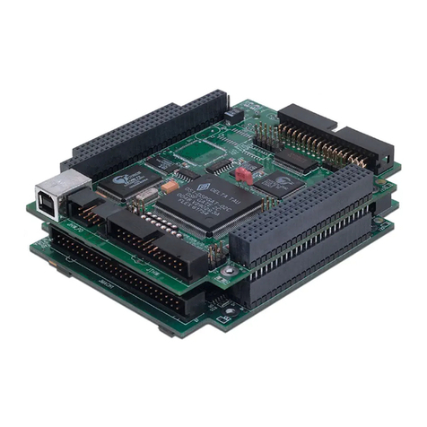
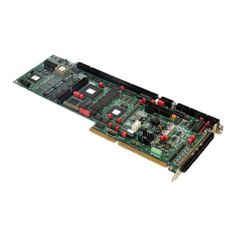
Delta Tau PMAC User manual

Single Source Machine Control ……………………………………………..…...………………. Power // Flexibility // Ease of Use
21314 Lassen St. Chatsworth, CA 91311 // Tel. (818) 998-2095 Fax. (818) 998-7807 // www.deltatau.com
^1 USER’S MANUAL
^2 Power PMAC
^3Power PMAC User’s Manual
^4 050-PRPMAC-0U0
^5 January 6, 2015
DELTA TAU
Data Systems, Inc.
NEW IDEAS IN MOTION …

Power PMAC User’s Manual
Copyright Information
© 2015 Delta Tau Data Systems, Inc. All rights reserved.
This document is furnished for the customers of Delta Tau Data Systems, Inc. Other uses
are unauthorized without written permission of Delta Tau Data Systems, Inc.
Information contained in this manual may be updated from time-to-time due to product
improvements, etc., and may not conform in every respect to former issues.
To report errors or inconsistencies, call or email:
Delta Tau Data Systems, Inc. Technical Support
Phone: (818) 717-5656
Fax: (818) 998-7807
Email: suppor[email protected]
Website: http://www.deltatau.com
Operating Conditions
All Delta Tau Data Systems, Inc. motion controller products, accessories, and amplifiers
contain static sensitive components that can be damaged by incorrect handling. When
installing or handling Delta Tau Data Systems, Inc. products, avoid contact with highly
insulated materials. Only qualified personnel should be allowed to handle this
equipment.
In the case of industrial applications, we expect our products to be protected from
hazardous or conductive materials and/or environments that could cause harm to the
controller by damaging components or causing electrical shorts. When our products are
used in an industrial environment, install them into an industrial electrical cabinet or
industrial PC to protect them from excessive or corrosive moisture, abnormal ambient
temperatures, and conductive materials. If Delta Tau Data Systems, Inc. products are
directly exposed to hazardous or conductive materials and/or environments, we cannot
guarantee their operation.

Power PMAC User’s Manual
Safety Instructions
Qualified personnel must transport, assemble, install, and maintain this equipment. Properly qualified
personnel are persons who are familiar with the transport, assembly, installation, and operation of
equipment. The qualified personnel must know and observe the following standards and regulations:
IEC364resp.CENELEC HD 384 or DIN VDE 0100
IEC report 664 or DIN VDE 0110
National regulations for safety and accident prevention or VBG 4
Incorrect handling of products can result in injury and damage to persons and machinery. Strictly adhere
to the installation instructions. Electrical safety is provided through a low-resistance earth connection. It
is vital to ensure that all system components are connected to earth ground.
This product contains components that are sensitive to static electricity and can be damaged by incorrect
handling. Avoid contact with high insulating materials (artificial fabrics, plastic film, etc.). Place the
product on a conductive surface. Discharge any possible static electricity build-up by touching an
unpainted, metal, grounded surface before touching the equipment.
Keep all covers and cabinet doors shut during operation. Be aware that during operation, the product has
electrically charged components and hot surfaces. Control and power cables can carry a high voltage,
even when the motor is not rotating. Never disconnect or connect the product while the power source is
energized to avoid electric arcing.
A Warning identifies hazards that could result in personal injury or
death. It precedes the discussion of interest.
Warning
!
Caution
A Caution identifies hazards that could result in equipment damage. It
precedes the discussion of interest.
Note
A Note identifies information critical to the understanding or use of
the equipment. It follows the discussion of interest.

Power PMAC User’s Manual
REVISION HISTORY
REV.
DESCRIPTION
DATE
CHG
APPVD
1
New Manual Generated
11/28/2011
SS
Curt Wilson
2
Updating Table of Contents
01/19/2012
SS
Curt Wilson
3
Updating the manual for firmware version 1.5 release
08/10/2012
SS
Curt Wilson
4
Updating the manual for firmware version 1.6 release
03/17/2014
SS
Curt Wilson
5
Updating the manual for firmware version 2.0 release
01/06/2015
SS
Curt Wilson


Power PMAC User’s Manual
Table of Contents vi
TABLE OF CONTENTS
Contents
POWER PMAC FAMILY OVERVIEW................................................................................................27
What Is Power PMAC?...............................................................................................................................27
Power PMAC Configurations.....................................................................................................................27
Power UMAC.........................................................................................................................................27
Compact Power UMAC.........................................................................................................................28
Power PMAC Etherlite..........................................................................................................................28
Power Brick Configurations..................................................................................................................28
Power Clipper........................................................................................................................................29
Soft Power PMAC..................................................................................................................................30
What Power PMAC Does...........................................................................................................................30
Execute Sequenced Motion Programs...................................................................................................30
Execute Asynchronous PLC Programs..................................................................................................30
Perform Kinematic Transformations.....................................................................................................30
Process Feedback and Master Position Data........................................................................................31
Compute Commanded Motor Trajectories............................................................................................31
Calculate Compensation Table Corrections..........................................................................................31
Close Motor Position/Velocity Servo Loops..........................................................................................31
Perform Electronic Phase Commutation...............................................................................................31
Close Motor Current Loops...................................................................................................................31
Provide Synchronous Data Gathering...................................................................................................32
Perform General Housekeeping and Safety Checks..............................................................................32
Respond to Host Computer Commands.................................................................................................32
Execute Independent C Applications.....................................................................................................32
Key Hardware Components........................................................................................................................33
CPU Section...........................................................................................................................................33
Machine Interface ICs ...........................................................................................................................34
TALKING TO POWER PMAC..............................................................................................................39
Physical Interface........................................................................................................................................39
Use of the Internet Protocol Suite...............................................................................................................39
Layers of the Internet Protocol Suite.....................................................................................................39
Low-Level Terminal Communications.......................................................................................................40
Terminal Emulator Programs................................................................................................................41
Establishing First Communications.......................................................................................................41

Power PMAC User’s Manual
Table of Contents vii
Communicating with the Power PMAC Control Application................................................................42
Establishing Communications with the IDE...............................................................................................44
Startup Communications Control Window............................................................................................44
Embedded Communications Control Window.......................................................................................45
Changing the Power PMAC IP Address................................................................................................46
Finding an Unknown IP Address...........................................................................................................47
Power PMAC Commands...........................................................................................................................48
On-Line (Immediate) Commands...........................................................................................................48
Buffered Program Commands...............................................................................................................50
Power PMAC Processing of Commands...............................................................................................51
POWER PMAC SYSTEM CONFIGURATION...................................................................................55
Physical Configuration Status Reporting....................................................................................................55
General Configuration...........................................................................................................................55
Interface ICs Present.............................................................................................................................56
Interface IC Addresses...........................................................................................................................56
Interface IC Configuration Information................................................................................................56
Change in Configuration.......................................................................................................................57
Power PMAC System Clock Source...........................................................................................................57
Default Clock Source.............................................................................................................................57
IC Clock Generation Facilities..............................................................................................................57
Distribution of Clock Signals.................................................................................................................58
Re-Initialization Clock Actions..............................................................................................................59
Normal Reset Clock Actions..................................................................................................................59
Changing the Clock Source from Default..............................................................................................60
Setting System Clock Frequencies..............................................................................................................60
Phase and Servo-Clock Hardware Tasks ..............................................................................................60
Phase-Clock Software Tasks..................................................................................................................61
Servo-Clock Software Tasks ..................................................................................................................61
Real-Time Interrupt Software Tasks......................................................................................................62
Background Tasks..................................................................................................................................63
Multi-Tasking Example..........................................................................................................................64
Using the IDE to Set Phase and Servo Clock Frequencies ...................................................................65
Setting Phase and Servo Clock Frequencies in PMAC2-Style ICs........................................................65
Setting Phase and Servo Clock Frequencies in PMAC3-Style ICs........................................................68
Clock-Related Software Settings............................................................................................................69
Setting the Phase and Servo Clock Period in the CPU .........................................................................70
Diagnosing Issues with Clock Settings.......................................................................................................71
Missing Clock Signals............................................................................................................................71
Task Priority Duty Cycles......................................................................................................................71

Power PMAC User’s Manual
Table of Contents viii
SETTING UP THE MACRO RING.......................................................................................................75
MACRO Ring Overview ............................................................................................................................75
Power PMAC MACRO Interfaces..............................................................................................................75
ACC-5E MACRO Interface for UMAC..................................................................................................75
ACC-5E3 MACRO Interface for UMAC................................................................................................75
ACC-5EP3 MACRO Interface for Etherlite...........................................................................................76
MACRO Interface for Power Brick .......................................................................................................76
Configuring Master and Slave Devices ......................................................................................................76
PMAC2-Style MACRO IC......................................................................................................................76
PMAC3-Style MACRO IC......................................................................................................................77
Setting the Ring Frequency.........................................................................................................................79
PMAC2-Style MACRO IC......................................................................................................................79
PMAC3-Style MACRO IC......................................................................................................................80
Extending the Phase Software Update...................................................................................................80
Enabling MACRO Nodes ...........................................................................................................................82
Node Allocation.....................................................................................................................................82
Typical Mapping of MACRO Nodes to Motors .....................................................................................82
Enabling Nodes in a PMAC2-Style MACRO IC....................................................................................83
Enabling Nodes in a PMAC3-Style MACRO IC....................................................................................84
Ring Check Function ..................................................................................................................................85
Ring Check Parameters.........................................................................................................................85
MACRO Node Register Organization........................................................................................................85
Standard Use of Registers in a Servo Node...........................................................................................85
Data Elements in a PMAC2-Style MACRO IC......................................................................................85
Data Elements in a PMAC3-Style MACRO IC......................................................................................86
Processing Position Feedback from the MACRO Ring..............................................................................86
Encoder Table Entry Method: EncTable[n].type..................................................................................86
Encoder Table Entry Source Address: EncTable[n].pEnc....................................................................87
Intermediate Processing: EncTable[n].index1, index2 .........................................................................88
Change Limiting: EncTable[n].index3, MaxDelta................................................................................89
Setting Up Motor Addressing Elements .....................................................................................................90
Command Output Address.....................................................................................................................90
Position Feedback Address....................................................................................................................91
Interface Type........................................................................................................................................91
Input Flag Addresses.............................................................................................................................91
Input Flag Bits.......................................................................................................................................91
Output Flag Addresses ..........................................................................................................................92
Output Flag Bits ....................................................................................................................................92

Power PMAC User’s Manual
Table of Contents ix
Commutation Addresses ........................................................................................................................93
Setting Up a Motor as a Network Slave......................................................................................................95
Command Modes...................................................................................................................................95
Coordinating Power PMAC Motor Setup..............................................................................................96
Network-Slave Power PMAC Motor Setup............................................................................................99
SETTING UP FEEDBACK AND MASTER POSITION SENSORS................................................102
Setting Up Digital Quadrature Encoders ..................................................................................................102
Signal Format......................................................................................................................................102
Hardware Setup...................................................................................................................................103
Hardware-Control Parameter Setup...................................................................................................105
Using the Resulting Position Information ...........................................................................................107
Setting Up Digital Hall Sensors................................................................................................................110
Signal Format......................................................................................................................................110
Hardware Setup...................................................................................................................................111
Hardware-Control Parameter Setup...................................................................................................111
Using the Resulting Position Information ...........................................................................................112
Setting Up Serial Encoders.......................................................................................................................113
Signal Format......................................................................................................................................113
Hardware Setup...................................................................................................................................113
Hardware-Control Parameter Setup...................................................................................................113
Using the Resulting Position Information ...........................................................................................123
Setting Up Analog Sinusoidal Encoders...................................................................................................127
Signal Format......................................................................................................................................127
Sinusoidal Encoder Interfaces.............................................................................................................128
Hardware Setup...................................................................................................................................129
Hardware Control Parameter Setup....................................................................................................131
Using the Resulting Position Information ...........................................................................................143
Setting Up Resolvers.................................................................................................................................149
Signal Format......................................................................................................................................149
Hardware Setup...................................................................................................................................150
Hardware-Control Parameter Setup...................................................................................................150
Using the Resulting Position Information ...........................................................................................153
Setting Up MLDTs ...................................................................................................................................157
Signal Format......................................................................................................................................157
Hardware Setup...................................................................................................................................158
Hardware-Control Parameter Setup...................................................................................................158
Using the Resulting Position Information ...........................................................................................161
Setting Up Parallel Data Position Inputs...................................................................................................163

Power PMAC User’s Manual
Table of Contents x
Signal Format......................................................................................................................................163
Hardware Setup...................................................................................................................................163
Hardware Control Parameter Setup....................................................................................................163
Using the Resulting Position Information ...........................................................................................164
Setting Up Analog Data Position Inputs...................................................................................................166
Signal Format......................................................................................................................................166
Hardware Setup...................................................................................................................................167
Hardware Control Parameter Setup....................................................................................................168
Using the Resulting Position Information ...........................................................................................171
SETTING UP THE ENCODER CONVERSION TABLE..................................................................177
What the Encoder Conversion Table Does...............................................................................................177
Conversion Table Execution.....................................................................................................................178
Conversion Table Structure ......................................................................................................................178
Conversion Method Overview..................................................................................................................179
IDE Table Configuration Window............................................................................................................179
Scaling of Entry Results............................................................................................................................180
Using Conversion Table Results...............................................................................................................181
Default Conversion Table Setup...............................................................................................................182
Conversion Method Details ......................................................................................................................182
Type 0: End of (Active) Table..............................................................................................................182
Type 1: Single-Register Read ..............................................................................................................183
Type 2: Double-Register Read.............................................................................................................189
Type 3: Software 1/T Encoder Extension ............................................................................................191
Type 4: Software Arctangent Sinusoidal Encoder Extension..............................................................192
Type 5: Four-Byte Read.......................................................................................................................196
Type 6: Resolver Arctangent Direct Conversion.................................................................................197
Type 7: Extended Hardware Arctangent Interpolation.......................................................................198
Types 8 and 9: Addition and Subtraction ............................................................................................199
Type 10: Triggered Time Base.............................................................................................................200
Type 11: Floating-Point Register Read...............................................................................................201
Type 12: Single Register Read with Error Check................................................................................203
BASIC MOTOR SETUP........................................................................................................................206
IDE Interactive Setup................................................................................................................................207
Parameters to Set Up Basic Motor Operation...........................................................................................207

Power PMAC User’s Manual
Table of Contents xi
Initial Setup Parameters............................................................................................................................209
Activating the Motor: Motor[x].ServoCtrl ..........................................................................................209
Activating PMAC Motor Commutation: Motor[x].PhaseCtrl.............................................................209
Motor Address Setup Parameters..............................................................................................................210
Command Output Address: Motor[x].pDac........................................................................................210
Motor vs. Load Feedback....................................................................................................................211
Outer (Position) Loop Feedback: Motor[x].pEnc, PosSf....................................................................212
Inner (Velocity) Loop Feedback: Motor[x].pEnc2, Pos2Sf.................................................................212
Changing Feedback on the Fly............................................................................................................213
Feedback Source and Type: Motor[x].EncType..................................................................................213
Encoder Status Address: Motor[x].pEncStatus...................................................................................214
Position-Capture Flag Address: Motor[x].pCaptFlag, CaptFlagBit..................................................214
Limit Flag Address: Motor[x].pLimits, LimitBits................................................................................214
Amplifier Fault Flag Address: Motor[x].pAmpFault, AmpFaultBit ...................................................215
Amplifier Enable Flag Address: Motor[x].pAmpEnable, AmpEnableBit............................................215
Absolute Power-On Position Address: Motor[x].pAbsPos .................................................................216
Is Power PMAC Commutating or Closing the Current Loop for This Motor?.........................................217
Setting Up Power PMAC for Velocity or Torque Control .......................................................................217
Hardware Setup...................................................................................................................................217
ASIC Programmable Signal Setup.......................................................................................................220
Setting Up Power PMAC for Pulse-and-Direction Control......................................................................222
Hardware Setup...................................................................................................................................223
Signal Timing.......................................................................................................................................223
Power PMAC Parameter Setup...........................................................................................................224
Setting Up Power PMAC for Position-Output Control.............................................................................230
Power PMAC Parameter Setup...........................................................................................................230
SETTING UP POWER PMAC-BASED COMMUTATION AND/OR CURRENT LOOP............232
Selection of Phase Update Frequency.......................................................................................................232
Beginning Setup of Commutation.............................................................................................................232
Commutation Enable: Motor[x].PhaseCtrl.........................................................................................233
Commutation Position Feedback Source: Motor[x].pPhaseEnc.........................................................234
Commutation Position Source Processing: Motor[x].PhaseEncRightShift, Motor[x].PhaseEncLeftShift
.............................................................................................................................................................235
Commutation Position Scale Factor: Motor[x].PhasePosSf...............................................................235
Current Loop in Power PMAC or Not: Motor[x].pAdc ......................................................................236
Setting Up for Sine-Wave Output Control................................................................................................238
Hardware Setup...................................................................................................................................238
Motor Software Setup..........................................................................................................................240

Power PMAC User’s Manual
Table of Contents xii
Setting Up For Direct PWM Control........................................................................................................244
Introduction .........................................................................................................................................244
Digital Current Loop Principle of Operation......................................................................................244
Hardware Setup...................................................................................................................................247
Motor Software Setup..........................................................................................................................251
Direct PWM Control of Brush Motors .....................................................................................................261
Direct Microstepping with Direct PWM Control......................................................................................264
Principle of Operation.........................................................................................................................264
Speed Limitations.................................................................................................................................265
Hardware Setup...................................................................................................................................265
Encoder Conversion Table Entry Setup...............................................................................................265
Simulated Servo Loop Setup................................................................................................................266
Commutation and Current-Loop Setup................................................................................................267
Limiting Parameters............................................................................................................................269
Establishing a Phase Reference (Synchronous Motors)............................................................................270
Absolute Phasing Reads ......................................................................................................................272
Correcting an Approximate Phase Reference......................................................................................278
Finishing Setting Up Power PMAC Commutation (Direct PWM or Sine Wave), Asynchronous
(Induction) Motors....................................................................................................................................279
Calculating Motor[x].DtOverRotorTc Slip Constant..........................................................................279
Setting Motor[x].IdCmd Magnetization Current.................................................................................281
SETTING UP THE SERVO LOOP......................................................................................................283
Servo Update Rate ....................................................................................................................................283
Choosing an Update Rate....................................................................................................................283
Ramifications of Changing the Rate....................................................................................................283
Setting the Servo Clock Frequency/Period..........................................................................................284
Extending the Servo Update Period for a Motor.................................................................................284
Closing the Servo Loop Under the Phase Interrupt for a Motor.........................................................284
Types of Amplifiers..................................................................................................................................285
Amplifiers for Which Servo Produces Position Command..................................................................286
Amplifiers for Which Servo Produces Velocity Command..................................................................286
Amplifiers for Which Servo Produces Torque/Force Command.........................................................287
Selecting a Servo Algorithm.....................................................................................................................288
Position Command Output Algorithm......................................................................................................289
Basic PID Algorithm.................................................................................................................................289
Feedback Terms...................................................................................................................................290
Feedforward Filter ..............................................................................................................................292

Power PMAC User’s Manual
Table of Contents xiii
Standard Servo Algorithm ........................................................................................................................293
Polynomial Filters...............................................................................................................................293
Integration Mode.................................................................................................................................296
Friction Feedforward ..........................................................................................................................296
Acceleration Feedback ........................................................................................................................296
Input Deadband Compensation...........................................................................................................296
Output Hysteretic Deadband...............................................................................................................298
Adaptive Servo Control ............................................................................................................................299
Selecting the Adaptive Control Algorithm...........................................................................................300
Establishing the Reference System ......................................................................................................300
Software Setup for Adaptive Control...................................................................................................300
Gain Scheduled Adaptive Control .......................................................................................................301
Executing the Adaptive Control Algorithm..........................................................................................302
Cross-Coupled Gantry Control .................................................................................................................304
Selecting the Cross-Coupled Control Algorithm.................................................................................305
Tuning the Non-Coupled Terms...........................................................................................................305
Tuning the Cross-Coupled Terms........................................................................................................306
Custom User Servo Algorithms................................................................................................................306
Tuning the Servo Loop in the IDE............................................................................................................307
Automatic Tuning.................................................................................................................................308
Sample Interactive Tuning Process .....................................................................................................310
Cascading Servo Loops.............................................................................................................................315
Strategies for Coupling the Loops.......................................................................................................315
To Integrate Outer Loop Command or Not.........................................................................................316
Inner Loop General Setup ...................................................................................................................316
Outer Loop General Setup...................................................................................................................317
Joining the Loops through Position Following Function....................................................................317
Joining the Loops through Compensation Table.................................................................................319
Tuning the Outer Loop.........................................................................................................................321
Programming the Outer-Loop Motor..................................................................................................322
Setup Examples....................................................................................................................................322
Changing the Operational Mode of Control........................................................................................324
Trajectory Pre-Filter..................................................................................................................................325
Typical Uses of the Pre-Filter .............................................................................................................325
Overview..............................................................................................................................................326
Saved Setup Elements ..........................................................................................................................327
Filter DC Gain.....................................................................................................................................327
Spliner Reconstruction.........................................................................................................................328
Automated Filter Setup........................................................................................................................328
Manual Filter Calculations .................................................................................................................329

Power PMAC User’s Manual
Table of Contents xiv
SETTING UP COMPENSATION TABLES........................................................................................332
Table Data Structure.................................................................................................................................332
Reserving Memory for the Tables ............................................................................................................333
Defining the Table Structure.....................................................................................................................334
Dimension Indices ...............................................................................................................................334
Number of Active Dimensions: Nx[n] > 0...........................................................................................334
Source Motors for Each Dimension: Source[n]..................................................................................336
Source Position Used for Each Dimension: SourceCtrl......................................................................336
Number of Data Zones in Each Active Dimension: Nx[n] ..................................................................336
Starting Source Location for Each Active Dimension: X0[n] .............................................................337
Source Span for Each Active Dimension: Dx[n].................................................................................337
Interpolation-Order and Boundary-Mode Control: Ctrl.....................................................................338
Target Register Addresses: Target[q].................................................................................................340
Target Output Scale Factors: Sf[q].....................................................................................................343
Overwriting vs. Additive Outputs: OutCtrl..........................................................................................343
Entering the Table Data Points .................................................................................................................344
Enabling Compensation Tables ................................................................................................................345
Action of the Compensation Tables..........................................................................................................345
Use of “0D” Compensation Tables...........................................................................................................346
Sample Compensation Tables...................................................................................................................347
1D “Leadscrew Compensation” Table................................................................................................347
2D “Planar” Position Compensation Table .......................................................................................347
SETTING UP ELECTRONIC CAM TABLES ...................................................................................349
Uses of Electronic Cam Tables.................................................................................................................349
Position Commands.............................................................................................................................349
Torque Offset Commands ....................................................................................................................349
Direct Output Commands....................................................................................................................349
Comparison to External Time Base Techniques.......................................................................................350
Table Design Techniques..........................................................................................................................351
Table Data Structure.................................................................................................................................352
Reserving Memory for the Tables ............................................................................................................353
Defining the Table Structure.....................................................................................................................353
Source Motor Number: Source............................................................................................................353

Power PMAC User’s Manual
Table of Contents xv
Number of Data Zones: Nx..................................................................................................................354
Starting Source Location: X0, SlewX0 ................................................................................................354
Source Span: Dx..................................................................................................................................355
Target Motor Number: Target.............................................................................................................355
Target Position Scale Factor: PosSf ...................................................................................................355
Target Position Offset Slew: SlewPosOffset........................................................................................355
Target Torque Offset Enable Control: DacEnable..............................................................................355
Target Torque Scale Factor: DacSf.....................................................................................................355
Output Address: pOut..........................................................................................................................355
Buffered Output Address: pOutBuf......................................................................................................356
Output Shifting:OutLeftShift................................................................................................................356
Output Masking: OutBits.....................................................................................................................356
Entering the Table Data Points .................................................................................................................356
Returning vs. Non-Returning Position Tables..........................................................................................357
Returning Position Tables ...................................................................................................................357
Non-Returning Position Tables ...........................................................................................................358
Enabling the Cam Tables..........................................................................................................................359
Action of the Cam Tables.........................................................................................................................359
Adjusting of the Table Action...................................................................................................................361
Adjusting on Source Motor Position....................................................................................................361
Adjusting on Target Motor Position....................................................................................................361
Phasing the Cam Cycle on a Source Motor Trigger ...........................................................................361
Rollover of the Table................................................................................................................................363
Position Output at Rollover.................................................................................................................363
Torque Offset Output at Rollover ........................................................................................................363
General Purpose Outputs at Rollover .................................................................................................364
Iterative Learning Control.........................................................................................................................364
Combining Cam Motion with Other Motion ............................................................................................364
Reporting Motor Position with Cam Table Motion..................................................................................365
Disabling the Cam Tables.........................................................................................................................365
Switching Between Cam Tables...............................................................................................................365
MAKING YOUR POWER PMAC APPLICATION SAFE ...............................................................366
Watchdog Timer .......................................................................................................................................366
Soft Watchdog Trips ............................................................................................................................366
Hard Watchdog Trips..........................................................................................................................368
Global Abort-All Input .............................................................................................................................369

Power PMAC User’s Manual
Table of Contents xvi
Software Setup.....................................................................................................................................369
Action on Trip......................................................................................................................................369
Voltage Interlock Circuits.........................................................................................................................370
Following Error Limits.............................................................................................................................370
Fatal Following Error Limit................................................................................................................370
Warning Following Error Limit ..........................................................................................................372
Position (Overtravel) Limits .....................................................................................................................372
Software Overtravel Limit Parameters................................................................................................372
Hardware Overtravel Limit Switches..................................................................................................374
Encoder Loss Detection............................................................................................................................376
Signal Loss Detection Circuits ............................................................................................................377
Software Setup for Loss Detection.......................................................................................................379
Auxiliary Fault Detection .........................................................................................................................381
Software Setup for Auxiliary Fault Detection......................................................................................381
Automatic Brake Control..........................................................................................................................383
Specifying the Brake Control Output...................................................................................................383
Specifying the Brake Timing................................................................................................................383
Amplifier Enable and Fault Lines.............................................................................................................384
Current Limits...........................................................................................................................................385
Intermittent Current Limits..................................................................................................................385
Time-Integrated Current Limits...........................................................................................................386
RMS Current Calculations ..................................................................................................................389
Reference Frame Conversions.............................................................................................................392
Torque Control Mode..........................................................................................................................393
Sinewave Output Mode........................................................................................................................395
Direct PWM Output Mode...................................................................................................................397
Velocity Limits .........................................................................................................................................400
Programmed Vector Velocity Limit.....................................................................................................400
Programmed Motor Velocity Limit......................................................................................................401
Position-Following Velocity Limit.......................................................................................................401
Acceleration Limits...................................................................................................................................401
Programmed Vector Acceleration Limits............................................................................................401
Programmed Motor Acceleration Limits.............................................................................................402
Motor Move Acceleration Command...................................................................................................403
Position-Following Acceleration Limit ...............................................................................................403
Jerk Limits ................................................................................................................................................403
Programmed Motor Jerk Limit............................................................................................................403

Power PMAC User’s Manual
Table of Contents xvii
Motor Move Jerk Command................................................................................................................403
Commanded Safety Stops.........................................................................................................................404
Abort: Controlled Stop ........................................................................................................................404
Disable: Uncontrolled Stop.................................................................................................................404
Hybrid Abort/Disable ..........................................................................................................................405
EXECUTING INDIVIDUAL MOTOR MOVES.................................................................................406
Jogging Move Control ..............................................................................................................................406
Jog Speed Control................................................................................................................................406
Jog Acceleration Control.....................................................................................................................406
Example Jog Move Profile...................................................................................................................410
Jog Commands.....................................................................................................................................410
Triggered Motor Moves............................................................................................................................412
Types of Triggered Moves ...................................................................................................................412
Trigger Conditions...............................................................................................................................413
Capturing the Position at Trigger .......................................................................................................417
Processing the Hardware-Captured Position......................................................................................421
Processing the Software-Captured Position........................................................................................430
Post-Trigger Move...............................................................................................................................430
Homing-Search Moves.........................................................................................................................430
Jog-Until-Trigger Moves.....................................................................................................................435
Program Move-Until-Trigger..............................................................................................................436
Open-Loop Moves....................................................................................................................................436
SETTING UP COORDINATE SYSTEMS ..........................................................................................437
What is a Coordinate System?..................................................................................................................437
Number of Coordinate Systems ...........................................................................................................437
Strategy for Assigning Coordinate Systems.........................................................................................437
Fault Sharing.......................................................................................................................................438
What is an Axis?.......................................................................................................................................438
Single-Motor Axes ...............................................................................................................................438
Multiple-Motor Axes............................................................................................................................438
Phantom Axes ......................................................................................................................................439
Axis Definition Statements.......................................................................................................................439
Matching Motor to Axis.......................................................................................................................440
Scaling and Offset................................................................................................................................440
The Null Definition..............................................................................................................................440
Defining a Motor to Multiple Axes......................................................................................................440
Cartesian Axis Sets..............................................................................................................................442
The Spindle Axis Definition.................................................................................................................443

Power PMAC User’s Manual
Table of Contents xviii
Conversion from Axis to Motor Position.............................................................................................444
Conversion from Motor to Axis Positions............................................................................................444
Coordinate-System Kinematic Subroutines..............................................................................................446
Creating the Kinematic Program Buffers............................................................................................447
Generalizing the Routines to Multiple Coordinate Systems................................................................457
Axis Transformation Matrices..................................................................................................................460
Transformation Matrix Data Structures..............................................................................................461
Using the Matrices...............................................................................................................................462
Examples..............................................................................................................................................463
Rescaling Feedrate and Tool Radius...................................................................................................464
Segmentation Mode..................................................................................................................................464
Time-Base Control and Override Techniques...........................................................................................466
Time-Base Control...............................................................................................................................466
Segmentation Override........................................................................................................................469
Axis Target Position and Distance-to-Go Reporting................................................................................472
Setting Up the Target Position Buffer..................................................................................................472
Querying the Target Position Data .....................................................................................................473
POWER PMAC COMPUTATIONAL FEATURES...........................................................................476
Computational Priorities...........................................................................................................................476
Phase (Commutation) Update .............................................................................................................476
Servo Update .......................................................................................................................................476
Real-Time Interrupt Tasks...................................................................................................................477
Background Tasks................................................................................................................................477
Monitoring Processing Time ...............................................................................................................477
Numerical Values......................................................................................................................................478
Internal Formats..................................................................................................................................478
Pre-Defined Data Structures.....................................................................................................................481
Specifying Data Structure Indices.......................................................................................................482
User Variables...........................................................................................................................................483
Direct Access to User Variables..........................................................................................................483
User-Specified Variable Names Through IDE ....................................................................................484
Automatically Assigned Declared Variables.......................................................................................484
System Global (“P”) Variables ...........................................................................................................486
Coordinate System Global (“Q”) Variables .......................................................................................487
User Pointer (“M”) Variables.............................................................................................................488
Pre-Defined Setup Pointer (“I”) Variables.........................................................................................488
Local (“L”) Variables .........................................................................................................................489

Power PMAC User’s Manual
Table of Contents xix
Return/Stack (“R”) Variables..............................................................................................................490
Coordinate System Kinematic Axis (“C”) Variables...........................................................................491
Non-Stack Local (“D”) Variables .......................................................................................................492
User Shared Memory Buffer Variables ...............................................................................................493
Operators...................................................................................................................................................495
Arithmetic Operators...........................................................................................................................495
Bit-Wise Operators..............................................................................................................................495
Standard Assignment Operators..........................................................................................................496
Synchronous Assignment Operators....................................................................................................496
Functions...................................................................................................................................................497
Scalar Functions..................................................................................................................................497
Vector Functions..................................................................................................................................497
Matrix Functions .................................................................................................................................498
Expressions...............................................................................................................................................499
The {data} Syntax.....................................................................................................................................500
Standard Variable Value Assignment.......................................................................................................500
Synchronous Variable Value Assignment ................................................................................................501
Variables That Can Be Assigned Synchronously.................................................................................501
Why Needed in Motion Programs........................................................................................................502
Why Needed in PLC Programs............................................................................................................503
The Synchronous Assignment Buffer ...................................................................................................503
Execution Details.................................................................................................................................504
Comparators..............................................................................................................................................504
Conditions.................................................................................................................................................505
Explicit Comparisons...........................................................................................................................505
Compound Conditions.........................................................................................................................505
Condition Negation..............................................................................................................................506
USING GENERAL-PURPOSE DIGITAL I/O WITH POWER PMAC...........................................507
Note on Using “Dedicated” I/O for General Purpose Use........................................................................507
Digital I/O Hardware and Configuration..................................................................................................507
UMAC Digital I/O Boards...................................................................................................................507
Compact UMAC ACC-11C Digital I/O...............................................................................................508
UMAC ACC-5E Digital I/O.................................................................................................................509
UMAC ACC-5E3 Digital I/O...............................................................................................................509
Power Brick Digital I/O.......................................................................................................................510
Power Clipper Digital I/O...................................................................................................................510
ACC-34 Family Multiplexed Digital I/O.............................................................................................511

Power PMAC User’s Manual
Table of Contents xx
Software Configuration for Digital I/O Use .............................................................................................513
UMAC Digital I/O Boards...................................................................................................................513
Compact UMAC ACC-11C Digital I/O...............................................................................................515
UMAC ACC-5E Digital I/O.................................................................................................................515
UMAC ACC-5E3 Digital I/O...............................................................................................................517
Power Brick Digital I/O.......................................................................................................................518
Power Clipper Digital I/O...................................................................................................................518
ACC-34 Family Multiplexed Digital I/O.............................................................................................519
Accessing Digital I/O Points in the Script Environment ..........................................................................523
Accessing Output Points at Different Priority Levels..........................................................................523
UMAC Digital I/O Boards...................................................................................................................524
Compact UMAC ACC-11C Digital I/O...............................................................................................525
UMAC ACC-5E Digital I/O.................................................................................................................525
UMAC ACC-5E3 Digital I/O...............................................................................................................526
Power Brick Digital I/O.......................................................................................................................526
Power Clipper Digital I/O...................................................................................................................527
ACC-34 Family Multiplexed Digital I/O.............................................................................................528
Accessing Digital I/O Points in the C Environment .................................................................................529
Accessing Output Points at Different Priority Levels..........................................................................529
Volatile Variable Declarations............................................................................................................529
Using Data Structures .........................................................................................................................529
Using Direct Pointer Variables...........................................................................................................530
UMAC Digital I/O Boards...................................................................................................................531
Compact UMAC ACC-11C Digital I/O...............................................................................................532
UMAC ACC-5E Digital I/O.................................................................................................................532
UMAC ACC-5E3 Digital I/O...............................................................................................................534
Power Brick Digital I/O.......................................................................................................................535
Power Clipper Digital I/O...................................................................................................................537
ACC-34 Family Multiplexed Digital I/O.............................................................................................538
USING GENERAL-PURPOSE ANALOG I/O WITH POWER PMAC...........................................539
Note on Using “Dedicated” I/O for General Purpose Use........................................................................539
Analog I/O Hardware and Configuration..................................................................................................539
UMAC ACC-28E ADC Board .............................................................................................................539
UMAC ACC-36E ADC Board .............................................................................................................540
UMAC ACC-59E ADC/DAC Board ....................................................................................................541
UMAC ACC-59E3 ADC/DAC Board ..................................................................................................541
Power Brick Optional Analog I/O.......................................................................................................543
Power Clipper Optional On-Board Analog I/O...................................................................................544
Power Clipper with ACC-28B ADC Board .........................................................................................545
Power Clipper with ACC-8AS True DAC Board.................................................................................545
Software Configuration for Analog I/O Use.............................................................................................546
Other manuals for PMAC
2
Table of contents
Other Delta Tau Controllers manuals

Delta Tau
Delta Tau PMAC User manual

Delta Tau
Delta Tau Power PMAC Clipper User manual

Delta Tau
Delta Tau Universal PMAC Lite Quick user guide

Delta Tau
Delta Tau Turbo PMAC2 PCI Ultralite Quick user guide

Delta Tau
Delta Tau ACC-11E User manual

Delta Tau
Delta Tau PMAC2A-PC/104 Quick user guide

Delta Tau
Delta Tau PMAC PC User manual

Delta Tau
Delta Tau PBC Series Operating and maintenance manual

Delta Tau
Delta Tau Turbo PMAC Clipper Quick user guide

Delta Tau
Delta Tau PMAC 1.5 Lite Quick user guide