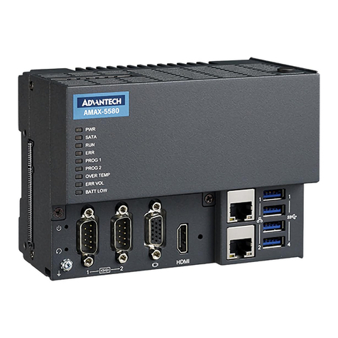
Delta Tau 5XX-603869-XUXX User manual

^3 Programmable Multi-Axis Controller
^4 5XX-603869-XUXX
^5 December 14, 2012
^1 USER MANUAL
^2 Brick Controller
Single Source Machine Control Power // Flexibility // Ease of Use
21314 Lassen Street Chatsworth, CA 91311 // Tel. (818) 998-2095 Fax. (818) 998-7807 // www.deltatau.com

Copyright Information
© 2011 Delta Tau Data Systems, Inc. All rights reserved.
This document is furnished for the customers of Delta Tau Data Systems, Inc. Other uses are
unauthorized without written permission of Delta Tau Data Systems, Inc. Information contained in this
manual may be updated from time-to-time due to product improvements, etc., and may not conform in
every respect to former issues.
To report errors or inconsistencies, call or email:
Delta Tau Data Systems, Inc. Technical Support
Phone: (818) 717-5656
Fax: (818) 998-7807
Email: support@deltatau.com
Web: www.deltatau.com
Operating Conditions
All Delta Tau Data Systems, Inc. motion controller, accessory, and amplifier products contain static
sensitive components that can be damaged by incorrect handling. When installing or handling Delta Tau
Data Systems, Inc. products, avoid contact with highly insulated materials. Only qualified personnel
should be allowed to handle this equipment.
In the case of industrial applications, we expect our products to be protected from hazardous or
conductive materials and/or environments that could cause harm to the controller by damaging
components or causing electrical shorts. When our products are used in an industrial environment, install
them into an industrial electrical cabinet to protect them from excessive or corrosive moisture, abnormal
ambient temperatures, and conductive materials. If Delta Tau Data Systems, Inc. products are directly
exposed to hazardous or conductive materials and/or environments, we cannot guarantee their operation.

Brick Controller User Manual
Safety Instructions
Qualified personnel must transport, assemble, install, and maintain this equipment. Properly qualified
personnel are persons who are familiar with the transport, assembly, installation, and operation of
equipment. The qualified personnel must know and observe the following standards and regulations:
IEC364resp.CENELEC HD 384 or DIN VDE 0100
IEC report 664 or DIN VDE 0110
National regulations for safety and accident prevention or VBG 4
Incorrect handling of products can result in injury and damage to persons and machinery. Strictly adhere
to the installation instructions. Electrical safety is provided through a low-resistance earth connection. It
is vital to ensure that all system components are connected to earth ground.
This product contains components that are sensitive to static electricity and can be damaged by incorrect
handling. Avoid contact with high insulating materials (artificial fabrics, plastic film, etc.). Place the
product on a conductive surface. Discharge any possible static electricity build-up by touching an
unpainted, metal, grounded surface before touching the equipment.
Keep all covers and cabinet doors shut during operation. Be aware that during operation, the product has
electrically charged components and hot surfaces. Control and power cables can carry a high voltage,
even when the motor is not rotating. Never disconnect or connect the product while the power source is
energized to avoid electric arcing.
WARNING
A Warning identifies hazards that could result in personal injury
or death. It precedes the discussion of interest.
Caution
A Caution identifies hazards that could result in equipment damage. It
precedes the discussion of interest.
Note
A Note identifies information critical to the user’s understanding or
use of the equipment. It follows the discussion of interest.

Brick Controller User Manual
REVISION HISTORY
REVISION
DESCRIPTION
DATE
CHANGE
APPROVED
1
MANUAL CREATION
05/02/07
C.P
S.M
2
X15 WATCHDOG DESCRIPTION, P. 10
TB1 CURRENT REQUIREMENTS, P. 11
10/31/08
C.P
S.M
3
ADDED AUXILIARY BOARD INFO IN APPENDIX A
07/24/09
C.P
S.S
4
CORRECTED M5061 ENTRY, P. 27
09/29/09
C.P
M.Y
5
MANUAL REFORMATTING. ADDED MORE TECHNICAL INFO.
E.G. WIRING DIAGRAMS, SPECIAL FEEDBACK ECT…
11/7/11
M.Y
R.N
6
AMPLIFIER CONNECTION WIRING
12/27/11
R.N
R.N
7
GENERAL UPFATES, CORRECTIONS
11/13/12
R.N
R.N
8
- UPDATED PART NUMBER TREE
- UPDATED X9-X12 SECTION
- UPDATED MACRO CONNECTIVITY SECTION
- ADDED SERIAL N0 AND BOARD IDENTIFICATION
- GENERAL FORMATTING, CORRECTIONS, AND UPDATES
12/14/12
R.N
R.N

Brick Controller User Manual
Table Of Contents 5
Table of Contents
INTRODUCTION.....................................................................................................................8
Documentation............................................................................................................................8
Downloadable Turbo PMAC Script.............................................................................................9
SPECIFICATIONS.................................................................................................................10
Part Number..............................................................................................................................10
Options .....................................................................................................................................11
Environmental Specifications....................................................................................................12
RECEIVING AND UNPACKING .........................................................................................13
Use of Equipment .....................................................................................................................13
MOUNTING ...........................................................................................................................14
Connector Locations .................................................................................................................15
Mounting Dimensions...............................................................................................................16
CONNECTIONS AND SOFTWARE SETUP.......................................................................17
TB1: 24 VDC Logic Power.......................................................................................................17
+5V ENC PWR (Alternate Encoder Power) ..............................................................................18
Wiring the Alternate (+5V) Encoder Power..........................................................................19
Functionality, Safety Measures.............................................................................................20
X1-X8: Encoder Feedback, Digital A Quad B...........................................................................21
Setting up Quadrature Encoders...........................................................................................23
Encoder Count Error (Mxx18)..............................................................................................23
Encoder Loss Detection, Quadrature....................................................................................24
Step and Direction PFM Output (To External Stepper Amplifier) .........................................26
X1-X8: Encoder Feedback, Sinusoidal......................................................................................27
Setting up Sinusoidal Encoders.............................................................................................28
Counts per User Units..........................................................................................................29
Encoder Count Error (Mxx18)..............................................................................................30
Encoder Loss Detection, Sinusoidal......................................................................................31
X1-X8: Encoder Feedback, Resolver.........................................................................................32
Setting up Resolvers .............................................................................................................32
Resolver Excitation Magnitude.............................................................................................33
Resolver Excitation Frequency .............................................................................................33
X1-X8: Encoder Feedback, HiperFace ......................................................................................38
Setting up HiperFace On-Going Position .............................................................................39
Setting up HiperFace Absolute Power-On Position...............................................................41
Setting up HiperFace Encoders Example..............................................................................45
Encoder Count Error (Mxx18), HiperFace...........................................................................50
Encoder Loss Detection, HiperFace .....................................................................................50

Brick Controller User Manual
Table Of Contents 6
X1-X8: Encoder Feedback, SSI.................................................................................................52
Configuring SSI....................................................................................................................52
SSI Control Registers Setup Example....................................................................................56
X1-X8: Encoder Feedback, EnDat 2.1/2.2.................................................................................58
Configuring EnDat...............................................................................................................58
EnDat Control Registers Setup Example...............................................................................62
X1-X8: Encoder Feedback, BiSS C/B .......................................................................................64
Configuring BiSS..................................................................................................................64
BiSS Control Registers Setup Example .................................................................................68
Setting up SSI | EnDat | BiSS ....................................................................................................70
Setup Summary.....................................................................................................................71
Technique 1 Example............................................................................................................72
Technique 2 Example............................................................................................................75
Technique 3 Example............................................................................................................79
X1-X8: Encoder Feedback, Yaskawa Sigma II & III .................................................................83
Yaskawa Sigma II 16-Bit Absolute Encoder..........................................................................88
Yaskawa Sigma II 17-Bit Absolute Encoder..........................................................................91
Yaskawa Sigma III 20-Bit Absolute Encoder.........................................................................94
Yaskawa Sigma II 13-Bit Incremental Encoder.....................................................................97
Yaskawa Sigma II 17-Bit Incremental Encoder.....................................................................99
Yaskawa Incremental Encoder Alarm Codes ......................................................................101
Homing with Yaskawa Incremental Encoders .....................................................................102
X9-X10: Analog Inputs/Outputs..............................................................................................103
X11-X12: Analog Inputs/Outputs............................................................................................103
Setting up the Analog (ADC) Inputs....................................................................................104
Setting up the DAC Outputs................................................................................................105
Setting up the General Purpose Relay, Brake......................................................................107
Setting up the External Amplifier Fault Input......................................................................109
X13: USB 2.0 Connector........................................................................................................110
X14: RJ45, Ethernet Connector...............................................................................................110
X15: Watchdog & ABORT (TB2)...........................................................................................111
Wiring the Abort Input........................................................................................................111
Wiring the WatchDog (WD) Output....................................................................................112
J4: Limits, Flags, EQU [Axis 1- 4]..........................................................................................113
J5: Limits, Flags, EQU [Axis 5- 8]..........................................................................................114
Wiring the Limits and Flags ...............................................................................................115
Limits and Flags [Axis 1- 4] Suggested M-Variables..........................................................116
Limits and Flags [Axis 5- 8] Suggested M-Variables..........................................................116
J6: General Purpose Inputs/Outputs.........................................................................................117
J7: Additional General Purpose Inputs/Outputs .......................................................................118
J8: Additional General Purpose Inputs/Outputs .......................................................................119

Brick Controller User Manual
Table Of Contents 7
About the Digital Inputs and Outputs..................................................................................120
Wiring the Digital Inputs and Outputs................................................................................121
General Purpose I/Os (J6) Suggested M-Variables.............................................................122
General Purpose I/Os Additional (J7) Suggested M-Variables............................................122
General Purpose I/Os Additional (J8) Suggested M-Variables............................................123
J9: Handwheel Analog I/O ......................................................................................................124
Setting up the Analog Inputs (J9)........................................................................................125
Setting up the Analog Output (J9).......................................................................................127
Setting up Pulse and Direction Output PFM (J9)................................................................129
Setting up the Handwheel Port (J9) ....................................................................................131
Serial Port (RS232).................................................................................................................132
AMP1-AMP8: Amplifier Connection......................................................................................133
Wiring the DAC Output......................................................................................................134
Wiring the Amplifier Enable and Fault Signals...................................................................135
DRIVE-MOTOR SETUP .....................................................................................................137
Filtered PWM Output (Analog ±10V) .....................................................................................138
Clock Settings, Output Mode, Command Limit....................................................................139
Flag Control, Ixx24............................................................................................................139
I2T Protection: Ixx57, Ixx58...............................................................................................140
Open Loop Test: Encoder/Decode......................................................................................140
Position-Loop PID Gains: Ixx30…Ixx39.............................................................................142
True DAC Output (±10V).......................................................................................................143
Clock Settings, Output Mode ..............................................................................................143
Flag Control, Ixx24............................................................................................................143
I2T Protection: Ixx57, Ixx58...............................................................................................144
Open Loop Test: Encoder/Decode......................................................................................144
Position-Loop PID Gains: Ixx30…Ixx39.............................................................................146
Pulse and Direction Output (PFM) ..........................................................................................147
PFM Clock Settings Example .............................................................................................147
PFM Setup Example...........................................................................................................148
Writing directly to the PFM register...................................................................................148
Issuing Open-Loop Commands...........................................................................................149
Issuing Closed-Loop Commands.........................................................................................149
MACRO CONNECTIVITY .................................................................................................151
Introduction to MACRO .........................................................................................................151
MACRO Configuration Examples...........................................................................................152
Review: MACRO Nodes and Addressing.............................................................................153
Review: MACRO Auxiliary Commands...............................................................................154
Configuration Example 1: Brick - Brick..................................................................................155
Setting up the Slave ............................................................................................................155
Setting up the Master..........................................................................................................157

Brick Controller User Manual
Table Of Contents 8
Configuration Example 2: Brick - Geo MACRO Drive ...........................................................160
Brick –Brick MACRO I/O Data Transfer ...............................................................................168
Transferring the Digital (Discrete) Input and Outputs ........................................................169
Transferring the X9-X12 Analog Inputs/Outputs.................................................................174
Transferring the J9 Analog Inputs ......................................................................................176
MACRO Limits and Flags, Homing........................................................................................177
Limits and Flags.................................................................................................................177
Homing from Master ..........................................................................................................177
Homing from Slave.............................................................................................................177
MACRO Suggested M-Variables.........................................................................................178
Absolute Position Reporting over MACRO.............................................................................180
TROUBLESHOOTING........................................................................................................181
Serial Number and Board Revisions Identification ..................................................................181
Boot Switch SW (Firmware Reload) –Write-Protect Disable..................................................182
Reloading PMAC firmware.................................................................................................183
Changing IP Address, Gateway IP, Gateway Mask.............................................................185
Enabling ModBus...............................................................................................................186
Reloading Boot and Communication Firmware ..................................................................187
Reset Switch SW (Factory Reset)............................................................................................188
Watchdog Timer .....................................................................................................................188
APPENDIX A........................................................................................................................189
DB- Connector Spacing Specifications....................................................................................189
X1-8: DB-15 Connectors for encoder feedback...................................................................189
X9-12: DB-9 Connectors for Analog I/O.............................................................................189
Screw Lock Size for all DB-connectors...............................................................................189
APPENDIX B........................................................................................................................190
Schematics..............................................................................................................................190
AMP1-AMP8: Amplifier Fault / Amplifier Enable diagrams...............................................190
J6 and J7: General Purpose I/O........................................................................................191
J4: Limit Inputs for Axis 1-4..............................................................................................193
J5: Limit Inputs for Axis 5-8..............................................................................................194
APPENDIX C........................................................................................................................195
Absolute Serial Encoders Limitation with Turbo PMAC .........................................................195

Brick Controller User Manual
Introduction 8
INTRODUCTION
The Brick Motion Controller is a fully scalable automation controller utilizing
the intelligence and capability of its embedded Turbo PMAC2. With the ability
to store motion programs locally and built-in PLC execution, it is
programmable for virtually any kind of automation application. This allows for
complete machine motion and logic control.
The Brick Controller provides 4- or 8- axis of analog ±10V filtered-PWM (12-
bit), dual true-DAC (18-bit), or pulse and direction PFM outputs:
Analog ±10V (12-bit Filtered PWM)
Analog ±10V (18-bit True DAC)
PFM, Pulse and Direction Frequency Modulation
Documentation
In conjunction with this hardware reference manual, the Turbo Software Reference Manual and Turbo
PMAC User Manual are essential for proper use, motor setup, and configuration of the Brick Controller.
It is highly recommended to always refer to the latest revision of the manuals found on Delta Tau’s
website, under Support>documentation>Manuals: Delta Tau Manuals Link

Brick Controller User Manual
Introduction 9
Downloadable Turbo PMAC Script
Caution
Some code examples require the user to input specific information
pertaining to their system hardware. When user information is
required, a commentary ending with –User Input is inserted.
This manual contains downloadable code samples in Turbo PMAC script. These examples can be copied
and pasted into the editor area in the Pewin32pro2. Care must be taken when using pre-configured Turbo
PMAC code, some information may need to be updated to match hardware and system specific
configurations. Downloadable Turbo PMAC Scripts are enclosed in the following format:
// TURBO PMAC SCRIPT EXAMPLE
P1=0 ; Set P1=0 at download
Open PLC 1 Clear ; Open PLC Buffer 1, clear contents
CMDP"Brick controller Test PLC" ; Send unsolicited response to host port
P1=P1+1 ; Counter using variable P1
Disable PLC 1 ; Disable plc 1
Close ; Close open buffer
Caution
All PLC examples are stated in PLC number 1. It is the user’s
responsibility to arrange their application PLCs’ properly and handle
power-on sequencing for various tasks.
It is the user’s responsibility to use the PLC examples presented in this manual properly. That is,
incorporating the statement code in the application configuration, and handling tasks in a sequential
manner. For example, with serial absolute encoders, setting up the global control registers should be
executed before trying to read absolute position, and absolute phase referencing. Furthermore, other PLC
programs (which would be trying to move motors) should be disabled until these functions are executed.
Caution
Often times, downloadable example codes use suggested M-variables,
it is the user’s responsibility to make sure they are downloaded, or
perform necessary changes to use the intended registers.

Brick Controller User Manual
Specifications 10
SPECIFICATIONS
Part Number
BC 0 0000CF
-- - 04 00000
** ** ** **
CPU Options - Turbo PMAC 2 Processor
BCA-BB-CDD-EFG-HHHI0
C0: 80Mhz, 8Kx24 Internal, 256Kx24SRAM, 1MB Flash
(Default)
C3: 80Mhz, 8Kx24 Internal, 1Mx24SRAM, 4MB Flash
F3: 240Mhz, 192Kx24 Internal, 1Mx24SRAM, 4MB Flash
0: No options (Default)
2: Four GPIO Relays (On connectors X9-X12)
3: Two Analog In, two analog Out (On conn. X11-X12) & 4 GPIO Relays (On connectors X9-X12)
4: Four Analog In, four analog Out (On conn. X9-X12) & 4 GPIO Relays (On connectors X9-X12)
7: Two Analog In, 2 analog Out (Conn.X9-X10) & 4 GPIO Relays (On connectors X9-X12)
4
axes
Note: Analog outputs are 12-bit filtered PWM and Analog Inputs are 16-bit.
Analog I/O Options BCA-BB-CDD-EFG-HHHI0
8
axes
ABCDEFGHI
ABC
DE
F
Brick Controller Model Number Definition
Number of Axes
BCA-BB-CDD-EFG-HHHI0
4:Four Axes (Default)
8: Eight Axes
Axes 1 to 4 Options BCA-BB-CDD-EFG-HHHI0
F: Filtered-PWM analog output on Channels 1-4, 12-bit resolution
(default)
D: Dual true-DAC analog outputs on Channels 1-4, 18-bit resolution
Four primary encoder inputs. No secondary encoders, 4-axis system
Four secondary encoders for a total of 8 encoder inputs
4 Axes (Apply only to BC4-BB-CDD-EFG-HHHI0controller)
Axis 5-8 Feedback Options
Note: For Other Feedback Options See “Special Feedback Options”
12-24V 5V Flags
00 05
02 07
F2 F7
12-24V 5V Flags
-
D2 D7 Filtered-PWM analog output on Channels 5-8, 12-bit resolution
Dual true-DAC analog outputs on Channels 5-8, 18-bit resolution
8 Axes (Apply only to BC8-BB-CDD-EFG-HHHI0controller)
Axis 5-8 Options
Note: Letter must be same as previous letter
Digital I/O Option
BCA-BB-CDD-EFG-HHHI0
0: Digital I/O 16 inputs and 8 outputs, 0.5A, 24VDC (default)
1: Expanded digital I/O additional 16 inputs and 8 outputs, 0.5A, 24VDC
(Total of 32 IN / 16 OUT)
2: Expanded digital I/O additional 32 inputs and 16 outputs, 0.5A, 24VDC
(Total of 48 IN / 24 OUT)
0: No Analog Options available, for this configurations
2: Four GPIO Relays (On connectors X9-X12)
3: Two analog Inputs (On conn. X11-X12) & 4 GPIO Relays (On connectors X9-X12)
4: Four analog Inputs (On conn. X9-X12) & 4 GPIO Relays (On connectors X9-X12)
7: Two analog Inputs (Conn.X9-X10) & Four GPIO Relays (On connectors X9-X12)
Note: For Other Feedback Options See “Special Feedback Options”
Communication Options
BCA-BB-CDD-EFG-HHHI0
USB2 and Eth100 are included
Note: To use PMAC-NC software, DPRAM is required
0xxxxx: No Options, Default
Dxxxxx: DPRAM option, size 8K x 16-bit wide
Mxxxxx: ModBus Ethernet Communication Protocol (Software) option
Sxxxxx: DPRAM and Modbus Options Combined
R00000: RS232 port on 9-pin D-sub Connector*
E00000: DPRAM & RS232 Options Combined*
N00000: RS232 & ModBus Options Combined*
T00000: Modbus, DPRAM & RS232 Combined*
* If any of the “H” or “I” digits is non zero (BCA-BB-CDD-EFG-HHHI0)
then RS232 is included as default. Options R, E, N and T are Incompatible
G
MACRO and Special Feedback Options
MACRO Ring Interface and
8 Single or 4 Differential channel 12-bit
10v range MUXED ADC
BCA-BB-CDD-EFG-HHHI0
-xxx-xxx0x: No MACRO or ADC
-xxx-xxx1x: RJ45 MACRO
-xxx-xxx2x: Fiber Optic MACRO
-xxx-xxx3x: MUXED ADC
-xxx-xxx4x: RJ45 MACRO and MUXED ADC
-xxx-xxx5x: Fiber Optic MACRO and MUXED ADC
I
Special Feedback Number and Type of Channels
BCA-BB-CDD-EFG-HHHI0
000: No Special Feedback Channels
4A0: 4 Sinusoidal Encoder Feedback Channels
4B0: 4 Resolver Feedback Channels
4C1: 4 Serial Encoder Feedback Channels (SSI Protocol)
4C2: 4 Serial Encoder Feedback Channels (Yaskawa Sigma II & III Protocol)
4C3: 4 Serial Encoder Feedback Channels (EnDat 2.2 Protocol)
4C6: 4 Serial Encoder Feedback Channels (BISS-C Protocol)
4D1: 4 Sinusoidal Encoder and Serial Enc. (SSI Protocol)
4D2: 4 Sinusoidal Encoder and Serial Enc. (Yaskawa Sigma II & III Protocol)
4D3: 4 Sinusoidal Encoder and Serial Enc. (EnDat 2.1 / 2.2 Protocol)
4D4: 4 Sinusoidal Encoder and Serial Enc. (HiperFace Protocol)
4D6: 4 Sinusoidal Encoder and Serial Enc. (BISS-C Protocol)
4E1: 4 Resolver Feedback Channels and Serial Enc. (SSI Protocol)
4E2: 4 Resolver Feedback Ch. and Serial Enc. (Yaskawa Sigma II & III Prot.)
4E3: 4 Resolver Feedback Channels and Serial Enc. (EnDat 2.2 Protocol)
4E6: 4 Resolver Feedback Channels and Serial Enc. (BISS-C Protocol)
8A0: 8 Sinusoidal Encoder Feedback Channels
8B0: 8 Resolver Feedback Channels
8C1: 8 Serial Encoder Feedback Channels (SSI Protocol)
8C2: 8 Serial Encoder Feedback Channels (Yaskawa Sigma II & III Protocol)
8C3: 8 Serial Encoder Feedback Channels (EnDat 2.2 Protocol)
8C6: 8 Serial Encoder Feedback Channels (BISS-C Protocol)
8D1: 8 Sinusoidal Encoder and Serial Enc. (SSI Protocol)
8D2: 8 Sinusoidal Encoder and Serial Enc. (Yaskawa Sigma II & III Protocol)
8D3: 8 Sinusoidal Encoder and Serial Enc. (EnDat 2.1 / 2.2 Protocol)
8D4: 8 Sinusoidal Encoder and Serial Enc. (HiperFace Protocol)
8D6: 8 Sinusoidal Encoder and Serial Enc. (BISS-C Protocol)
8E1: 8 Resolver Feedback Channels and Serial Enc. (SSI Protocol)
8E2: 8 Resolver Feedback Ch. and Serial Enc. (Yaskawa Sigma II & III Prot.)
8E3: 8 Resolver Feedback Channels and Serial Enc. (EnDat 2.2 Protocol)
8E6: 8 Resolver Feedback Channels and Serial Enc. (BISS-C Protocol)
H
Note: If any of the “H” or “I” digits (BCA-BB-CDD-EFG-HHHI0) are ordered, you will also receive RS-232 comms port, 2 channel "handwheel" port.

Brick Controller User Manual
Specifications 11
Options
CPU Options
C0: 80MHz Turbo PMAC2 CPU (standard)
8Kx24 internal memory, 256Kx24 SRAM , 1MB flash memory
C3: 80MHz Turbo PMAC2 CPU
8Kx24 internal memory, 1Mx24 SRAM, 4M flash memory
F3: 240MHz Turbo PMAC2 CPU
192Kx24 internal memory, 1Mx24 SRAM, 4M flash memory
Encoder Feedback
Digital Quadrature
Sinusoidal
HiperFace
Resolver
SSI
EnDat 2.1 / 2.2
Yaskawa Sigma II / III
BiSS B / C
Panasonic
Tamagawa
Note
Regardless of the encoder feedback option(s) fitted, digital quadrature
encoders can always be utilized. However, Hall sensors cannot be
used with a channel which has been programmed for serial encoding.
Axis Output
18-bit true DAC or 12-bit filtered PWM (default) ±10V analog output
Pulse And Direction (PFM)
Encoder Input
Up to eight encoder inputs, and one handwheel quadrature input
Additional encoder inputs can be obtained through MACRO connectivity
Digital Inputs/Outputs
Up to 48 inputs and 24 outputs (Sinking or Sourcing)
Additional digital I/Os can be obtained through Fieldbus connectivity
Analog Inputs, DAC Outputs, Brakes, and Relays
Up to 4 x 16-bit analog inputs, 8 x 12-bit analog inputs, 4 x brake/ relay outputs , and 5 x 12-bit
filtered PWM (±10V) outputs
Communication
USB 2.0, Ethernet 100 Base T, RS232, DPRAM (required for NC software/applications)
FieldBus Connectivity
MACRO
ModBus

Brick Controller User Manual
Specifications 12
Environmental Specifications
Description
Specifications
Operating Temperature
0 to 45°C
Storage Temperature
-25°C to +70°C
Humidity
10% to 90% non-condensing
Operating Altitude
~3300 Feet (1000 m)
Air Flow Clearances
~3 inches (76.2mm) above and below unit for air flow
Operating Environment
Pollution Degree 2 or equivalent

Brick Controller User Manual
Receiving And Unpacking 13
RECEIVING AND UNPACKING
Delta Tau products are thoroughly tested at the factory and carefully packaged for shipment. When the
Brick Controller is received, there are several things to be done immediately:
Observe the condition of the shipping container and report any damage immediately to the
commercial carrier that delivered the drive.
Remove the Brick Controller from the shipping container and remove all packing materials. Check
all shipping material for connector kits, documentation, or other small pieces of equipment. Be aware
that some connector kits and other equipment pieces may be quite small and can be accidentally
discarded if care is not used when unpacking the equipment. The container and packing materials
may be retained for future shipment.
Verify that the part number of the Brick Controller received is the same as the part number listed on
the purchase order.
Inspect for external physical damage that may have been sustained during shipment and report any
damage immediately to the commercial carrier that delivered the drive.
Electronic components in this product are design-hardened to reduce static sensitivity. However, use
proper procedures when handling the equipment.
If the Brick Controller is to be stored for several weeks before use, be sure that it is stored in a
location that conforms to published storage humidity and temperature specifications.
Use of Equipment
The following restrictions will ensure the proper use of the Brick Controller:
The components built into electrical equipment or machines can be used only as integral components
of such equipment.
The Brick Controller must not be operated on power supply networks without a ground or with an
asymmetrical ground.
If the Brick Controller is used in residential areas, or in business or commercial premises, implement
additional filtering measures.
The Brick Controller may be operated only in a closed switchgear cabinet, taking into account the
ambient conditions defined in the environmental specifications.
Delta Tau guarantees the conformance of the Brick Controllers with the standards for industrial areas
stated in this manual, only if Delta Tau components (cables, controllers, etc.) are used.

Brick Controller User Manual
Mounting 14
MOUNTING
The location of the Brick Controller is important. Installation should be in an area that is protected from
direct sunlight, corrosives, harmful gases or liquids, dust, metallic particles, and other contaminants.
Exposure to these can reduce the operating life and degrade performance of the drive.
Several other factors should be carefully evaluated when selecting a location for installation:
For effective cooling and maintenance, the Brick Controller should be mounted on a smooth, non-
flammable vertical surface.
At least 76 mm (3 inches) top and bottom clearance must be provided for air flow. At least 10
mm (0.4 inches) clearance is required between units (each side).
Temperature, humidity and Vibration specifications should also be taken in account.
Caution
Unit must be installed in an enclosure that meets the environmental IP
rating of the end product (ventilation or cooling may be necessary to
prevent enclosure ambient from exceeding 45° C [113° F]).
The Brick Controller can be mounted with a 3-hole panel mount, two U shape/notches on the bottom and
one pear shaped holes on top.
If multiple Brick Controllers are used, they can be mounted side-by-side, leaving at least a 200 mm
clearance between them. It is extremely important that the airflow is not obstructed by the placement of
conduit tracks or other devices in the enclosure.
If the drive is mounted to a back panel, the back panel should be unpainted and electrically conductive to
allow for reduced electrical noise interference. The back panel should be machined to accept the
mounting bolt pattern.

Brick Controller User Manual
Mounting 15
Connector Locations
AMP 7
AMP 8
Analog I/O
Bottom View
24VDC
Logic Power
AMP 1
AMP 2
AMP 5
AMP 6
AMP 3
Alt. Enc. Pwr
Encoder #4
Encoder #3
Encoder #2
Encoder #1
USB
Ethernet
MACRO
Abort & WD
RS232
Analog I/O
Front View
AMP 4
Encoder #5
Encoder #6
Encoder #7
Encoder #8
General
Purpose I/O
Limits
& Flags
Top View

Brick Controller User Manual
Mounting 16
Mounting Dimensions
For both BC4-xx-xxx-xxx-xxxxx and BC8-xx-xxx-xxx-xxxxx:
Width
Depth
Height
3.50 inches (88.90 mm)
7.20 inches (182.88 mm)
15.00 inches (381 mm)
15.00"
(381.00 mm)
2.50"
(63.50 mm)
14.65"
(372.11 mm)
3.50"
(88.90 mm)
13.5"
(342.90 mm)
7.20"
(182.88 mm)
3x M4

Brick Controller User Manual
Connections And Software Setup 17
CONNECTIONS AND SOFTWARE SETUP
WARNING
Installation of electrical control equipment is subject to many
regulations including national, state, local, and industry guidelines
and rules. General recommendations can be stated but it is
important that the installation be carried out in accordance with
all regulations pertaining to the installation.
TB1: 24 VDC Logic Power
This 3-pin Phoenix Terminal Block is used to bring in the 24-Volt DC supply to power up the logic
portion of the Brick Controller.
The 24Volts power supply must be capable of providing 2~4Amps per Brick Controller. If multiple Brick
Controllers are sharing the same 24-Volt power supply, it is highly recommended to wire each one back
to the power supply terminals separately.
This connection can be made using 22 AWG wire directly from a protected power supply.
Pin #
Symbol
Function
Description
Notes
1
+24VDC
Input
Logic power input +
+16~32VDC
2
CHGND
Ground
Chassis ground
Machine Chassis
3
+24VDC RET
Common
Logic power return -
Power Supply Return
Phoenix PCB Edge Connector
Phoenix part #: ZEC 1,5/ 3-ST-5,0 C2 R1,3 (18883051)
Delta Tau part #: 014-188305-001 (For Internal Use)
123
+24 VDC
Power Supply
+24VDC
COM

Brick Controller User Manual
Connections And Software Setup 18
+5V ENC PWR (Alternate Encoder Power)
Typically, feedback devices are powered up through the X1-X8 connectors on the Brick Controller using
the internal +5VDC power supply. In some cases, feedback devices consume power excessively and risk
of surpassing the internal power supply limitation.
This connector provides an alternate mean to power-up the feedback devices (+5V only) if the total
encoder budget exceeds the specified thresholds.
Note
Encoders requiring greater than +5VDC power must be supplied
externally, and NOT through the X1-X8 connectors NOR through this
connector.
B C x - x x - x x x - x x x xxxxx
Add-in Board Options
-
If the Brick Controller is equipped with the add-in board, meaning any of the highlighted part number
digits is a non-zero, then the total +5V encoder power available at X1-X8 is about 1.5 amperes.
If the Brick Controller is not equipped with the add-in board, meaning all the highlighted part number
digits are zeros, then the total +5V encoder power available at X1-X8 is about 2 amperes.
Brick Controller
Total Encoder Power
Available [amps]
Power Per Encoder
(4 Encoders) [mA]
Power Per Encoder
(8 Encoders) [mA]
Without add-in board
1.5
375
188
with add-in board
2
500
250
Caution
The maximum current draw out of a single encoder channel must not
exceed 750 mA.

Brick Controller User Manual
Connections And Software Setup 19
Wiring the Alternate (+5V) Encoder Power
Pin#
Symbol
Description
Note
1
5VEXT
Input
5V from external power supply
2
5VINT
Output
Tie to pin#1 to use internal power supply
3
GND
Common
Mating Connector:
Adam-Tech part number 25CH-E-03
Pins part number 25CTE-R
Crimping tool: Molex EDP #11-01-0208
Caution
Only two of the three available pins should be used at one time. Do
not daisy-chain the internal 5V power supply with an external one.
By default, pins 1-2 are tied together to use the internal power supply. To wire an external power supply,
remove the jumper tying pins 1-2 and connect the external +5V to pin #1, and ground/common to pin#3:
Internal Power Supply
Wiring (Default)
External Power Supply
Wiring
1
2
3
1
2
3
+5V
Gnd
External
Power
Supply
Note
A jumper tying pins 1 and 2 is the default configuration. This is the
configuration with which the Brick Controller is shipped to a
customer.
Note
The controller (PMAC) 5V logic is independent of this scheme, so if
no encoder power is provided the PMAC will remain powered-up
(provided the standard 24 volts is brought in).
Other manuals for 5XX-603869-XUXX
1
Table of contents
Other Delta Tau Controllers manuals
Delta Tau
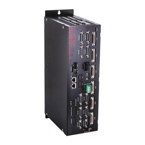
Delta Tau PBC Series Operating and maintenance manual
Delta Tau
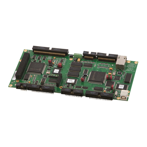
Delta Tau Turbo PMAC Clipper Quick user guide

Delta Tau
Delta Tau ACC-11E User manual

Delta Tau
Delta Tau PMAC2-PC Quick user guide
Delta Tau
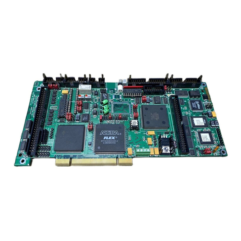
Delta Tau PMAC PC User manual

Delta Tau
Delta Tau Universal PMAC Lite Quick user guide

Delta Tau
Delta Tau PMAC2-PC Quick user guide

Delta Tau
Delta Tau PMAC User manual

Delta Tau
Delta Tau PMAC User manual
Delta Tau
Delta Tau PMAC 1.5 Lite Quick user guide
