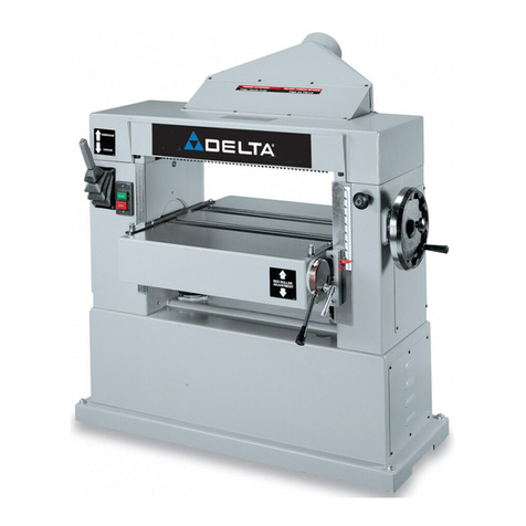
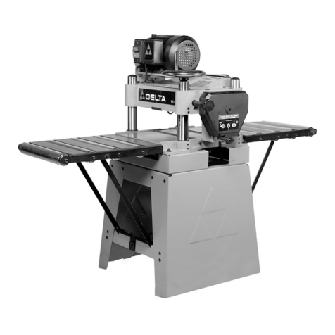
Delta 22-610 User manual

24-3/4" (629 mm)
Planer
Raboteuse de
629 mm (24-3/4 po)
Cepilladora de
629 mm (24-3/4 pulg.)
www.deltaportercable.com
(800) 223-7278 - US
(800) 463-3582 - CANADA
22-610
A26302 - 03-10-08 - Rev. A
Copyright © 2008 Delta Machinery
INSTRUCTIVO DE OPERACIÓN, CENTROS
DE SERVICIO Y PÓLIZA DE GARANTÍA.
LÉASE ESTE INSTRUCTIVO
ANTES DE USAR EL PRODUCTO.
Instruction manual
Manuel d’utilisation
Manual de instrucciones
FRANÇAIS (22) ESPAÑOL (42)

2
TABLE OF CONTENTS
IMPORTANT SAFETY INSTRUCTIONS
Read all warnings and operating instructions before using any tool or equipment. When
using tools or equipment, basic safety precautions should always be followed to reduce the risk of
personal injury. Improper operation, maintenance or modification of tools or equipment could result in
serious injury and property damage. There are certain applications for which tools and equipment are
designed. Delta Machinery strongly recommends that this product NOT be modified and/or used for any application
other than for which it was designed.
SAFETY GUIDELINES - DEFINITIONS
IMPORTANT SAFETY INSTRUCTIONS ....................2
SAFETY GUIDELINES - DEFINITIONS .....................2
GENERAL SAFETY RULES .......................................3
ADDITIONAL SPECIFIC SAFETY RULES ................4
CARTON CONTENTS ...............................................7
FUNCTIONAL DESCRIPTION ...................................8
ASSEMBLY .................................................................8
OPERATION ...............................................................10
If you have any questions relative to its application DO NOT use the product until you have written Delta Machinery and
we have advised you. Contact us online at www.deltaportercable.com or by mail at Technical Service Manager, Delta
Machinery, 4825 Highway 45 North, Jackson, TN 38305. In Canada,125 Mural St. Suite 300, Richmond Hill, ON, L4B 1M4)
Information regarding the safe and proper operation of this tool is available from the following sources:
• PowerToolInstitute,1300 Sumner Avenue, Cleveland, OH 44115-2851or online at www.powertoolinstitute.org
• NationalSafetyCouncil, 1121 Spring Lake Drive, Itasca, IL 60143-3201
• AmericanNationalStandardsInstitute, 25 West 43rd Street, 4 floor, New York, NY 10036 www.ansi.org - ANSI 01.1
Safety Requirements for Woodworking Machines
• U.S.DepartmentofLabor: www.osha.gov
SAVE THESE INSTRUCTIONS!
TROUBLESHOOTING................................................19
MAINTENANCE..........................................................19
SERVICE.....................................................................20
ACCESSORIES...........................................................21
WARRANTY................................................................21
FRANÇAIS ..................................................................22
ESPAÑOL....................................................................42
It is important for you to read and understand this manual. The information it contains relates to protecting YOUR SAFETY
and PREVENTING PROBLEMS. The symbols below are used to help you recognize this information.
Indicates an imminently hazardous situation which, if not avoided, will result in death or serious
injury.
Indicates a potentially hazardous situation which, if not avoided, could result in death or serious
injury.
Indicates a potentially hazardous situation which, if not avoided, may result in minor or moderate
injury.
Used without the safety alert symbol indicates a potentially hazardous situation which, if not avoided,
may result in property damage.
Some dust created by power sanding, sawing, grinding, drilling, and other construction activities
contains chemicals known to the State of California to cause cancer, birth defects or other reproductive harm.
Some examples of these chemicals are:
• leadfromlead-basedpaints,
• crystallinesilicafrombricksandcementandothermasonryproducts,and
• arsenicandchromiumfromchemically-treatedlumber.
Your risk from these exposures varies, depending on how often you do this type of work. To reduce your
exposure to these chemicals: work in a well ventilated area, and work with approved safety equipment, always
wear NIOSH/OSHA approved, properly fitting face mask or respirator when using such tools.

3
1. FOR YOUR OWN SAFETY, READ THE INSTRUCTION
MANUAL BEFORE OPERATING THE MACHINE.
Learning the machine’s application, limitations, and
specific hazards will greatly minimize the possibility
of accidents and injury.
2. WEAR EYE AND HEARING PROTECTION. ALWAYS
USE SAFETY GLASSES. Everyday eyeglasses are NOT
safety glasses. USE CERTIFIED SAFETY EQUIPMENT.
Eye protection equipment should comply with ANSI
Z87.1 standards. Hearing equipment should comply
with ANSI S3.19 standards.
3. WEAR PROPER APPAREL. Do not wear loose
clothing, gloves, neckties, rings, bracelets, or other
jewelry which may get caught in moving parts. Nonslip
protective footwear is recommended. Wear protective
hair covering to contain long hair.
4. DO NOT USE THE MACHINE IN A DANGEROUS
ENVIRONMENT. The use of power tools in damp or wet
locations or in rain can cause shock or electrocution.
Keep your work area well-lit to prevent tripping or
placing arms, hands, and fingers in danger.
5. MAINTAIN ALL TOOLS AND MACHINES IN PEAK
CONDITION. Keep tools sharp and clean for best and
safest performance. Follow instructions for lubricating
and changing accessories. Poorly maintained tools and
machines can further damage the tool or machine and/or
cause injury.
6. CHECK FOR DAMAGED PARTS. Before using the
machine, check for any damaged parts. Check for
alignment of moving parts, binding of moving parts,
breakage of parts, and any other conditions that may
affect its operation. A guard or any other part that is
damaged should be properly repaired or replaced
with Delta or factory authorized replacement parts.
Damaged parts can cause further damage to the
machine and/or injury.
7. KEEP THE WORK AREA CLEAN. Cluttered areas and
benches invite accidents.
8. KEEP CHILDREN AND VISITORS AWAY. Your shop is
a potentially dangerous environment. Children and visitors
can be injured.
9. REDUCE THE RISK OF UNINTENTIONAL STARTING.
Make sure that the switch is in the “OFF” position
before plugging in the power cord. In the event of a
power failure, move the switch to the “OFF” position.
An accidental start-up can cause injury. Do not touch
the plug’s metal prongs when unplugging or plugging in
the cord.
10. USE THE GUARDS. Check to see that all guards are in
place, secured, and working correctly to prevent injury.
11. REMOVE ADJUSTING KEYS AND WRENCHES
BEFORE STARTING THE MACHINE. Tools, scrap
pieces, and other debris can be thrown at high speed,
causing injury.
12. USE THE RIGHT MACHINE. Don’t force a machine or
an attachment to do a job for which it was not designed.
Damage to the machine and/or injury may result.
13. USE RECOMMENDED ACCESSORIES. The use of
accessories and attachments not recommended by
Delta may cause damage to the machine or injury to the
user.
14. USE THE PROPER EXTENSION CORD. Make sure
your extension cord is in good condition. When using
an extension cord, be sure to use one heavy enough to
carry the current your product will draw. An undersized
cord will cause a drop in line voltage, resulting in loss
of power and overheating. See the Extension Cord
Chart for the correct size depending on the cord length
and nameplate ampere rating. If in doubt, use the next
heavier gauge. The smaller the gauge number, the
heavier the cord.
15. SECURE THE WORKPIECE. Use clamps or a vise to
hold the workpiece when practical. Loss of control of a
workpiece can cause injury.
16. FEED THE WORKPIECE AGAINST THE DIRECTION
OF THE ROTATION OF THE BLADE, CUTTER, OR
ABRASIVE SURFACE. Feeding it from the other
direction will cause the workpiece to be thrown out at
high speed.
17. DON’T FORCE THE WORKPIECE ON THE MACHINE.
Damage to the machine and/or injury may result.
18. DON’T OVERREACH. Loss of balance can make you
fall into a working machine, causing injury.
19. NEVER STAND ON THE MACHINE. Injury could occur if
the tool tips, or if you accidentally contact the cutting tool.
20.NEVER LEAVE THE MACHINE RUNNING
UNATTENDED. TURN THE POWER OFF. Don’t leave the
machine until it comes to a complete stop. A child or visitor
could be injured.
21. TURN THE MACHINE “OFF”, AND DISCONNECT
THE MACHINE FROM THE POWER SOURCE before
installing or removing accessories, changing cutters,
adjusting or changing set-ups. When making repairs, be
sure to lock the start switch in the “OFF” position. An
accidental start-up can cause injury.
22. MAKE YOUR WORKSHOP CHILDPROOF WITH
PADLOCKS, MASTER SWITCHES, OR BY
REMOVING STARTER KEYS. The accidental start-up
of a machine by a child or visitor could cause injury.
23. STAY ALERT, WATCH WHAT YOU ARE DOING,
AND USE COMMON SENSE. DO NOT USE THE
MACHINE WHEN YOU ARE TIRED OR UNDER
THE INFLUENCE OF DRUGS, ALCOHOL, OR
MEDICATION. A moment of inattention while operating
power tools may result in injury.
24. USE OF THIS TOOL CAN
GENERATE AND DISBURSE DUST OR OTHER
AIRBORNE PARTICLES, INCLUDING WOOD DUST,
CRYSTALLINE SILICA DUST AND ASBESTOS DUST.
Direct particles away from face and body. Always
operate tool in well ventilated area and provide for
proper dust removal. Use dust collection system
wherever possible. Exposure to the dust may cause
serious and permanent respiratory or other injury,
including silicosis (a serious lung disease), cancer, and
death. Avoid breathing the dust, and avoid prolonged
contact with dust. Allowing dust to get into your mouth
or eyes, or lay on your skin may promote absorption
of harmful material. Always use properly fitting NIOSH/
OSHA approved respiratory protection appropriate for
the dust exposure, and wash exposed areas with soap
and water.
GENERAL SAFETY RULES
Failure to follow these rules may result in serious personal injury.

4
ADDITIONAL SPECIFIC SAFETY RULES
SAVE THESE INSTRUCTIONS.
Refer to them often and use them to instruct others.
1. DO NOT OPERATE THIS MACHINE until it is
completely assembled and installed according to
the instructions. A machine incorrectly assembled
can cause serious injury.
2. OBTAIN ADVICE from your supervisor, instructor,
or another qualified person if you are not thor-
oughly familiar with the operation of this machine.
Knowledge is safety.
3. FOLLOW ALL WIRING CODES and recom-
mended electrical connections to prevent shock
or electrocution.
4. KEEP KNIVES SHARP and free from rust and
pitch. Dull or rusted knives work harder and can
cause kickback.
5. NEVER TURN THE MACHINE “ON” before clearing
the table of all objects (tools, scraps of wood,
etc.). Flying debris can cause serious injury.
6. NEVER TURN THE MACHINE “ON” with the work-
piece contacting the cutterhead. Kickback can
occur.
7. SECURE THE MACHINE TO A SUPPORTING
SURFACE to prevent the machine from sliding,
walking or tipping over.
8. PROPERLY SECURE THE KNIVES IN THE CUTTER-
HEAD before turning the power “ON”. Loose
blades may be thrown out at high speeds causing
serious injury.
9. LOCK THE SPEED SETTING SECURELY before feed-
ing the workpiece through the machine. Changing
speeds while planing can cause kick-back.
10. AVOID AWKWARD OPERATIONS AND HAND
POSI- TIONS. A sudden slip could cause a hand
to move into the knives.
11. KEEP ARMS, HANDS, AND FINGERS away from
the cutterhead, the chip exhaust opening, and the
feed rollers to prevent severe cuts.
12. NEVER REACH INTO THE CUTTERHEAD AREA
while the machine is running. Your hands can be
drawn into the knives.
13. DO NOT STAND IN LINE OF THE WORKPIECE.
Kickback can cause injury.
14. ALLOW THE CUTTERHEAD TO REACH FULL
SPEED before feeding a workpiece. Changing
speeds while planing can cause kickback.
15. WHEN PLANING BOWED STOCK, place the concave
(cup down) side of the stock on the table and cut
with the grain to prevent kickback.
16. DO NOT FEED A WORKPIECE that is warped, con-
tains knots, or is embedded with foreign objects
(nails, staples, etc.). Kickback can occur.
17. DO NOT FEED A SHORT, THIN, OR NARROW WORK-
PIECE INTO THE MACHINE. Your hands can be
drawn into the knives and/or the workpiece can
be thrown at high speeds. See the “OPERATION”
section of this instruction manual for details.
18. DO NOT FEED A WORKPIECE into the outfeed end of
the machine. The workpiece will be thrown out of
the opposite side at high speeds.
19. REMOVE SHAVINGS ONLY with the power “OFF” to
prevent serious injury.
20. PROPERLY SUPPORT LONG OR WIDE WORKPIECES.
Loss of control of the workpiece can cause serious
injury.
21. NEVER PERFORM LAYOUT, ASSEMBLY or set-up
work on the table/work area when the machine is
running. Serious injury will result.
22. TURN THE MACHINE “OFF”, DISCONNECT IT FROM
THE POWER SOURCE, and clean the table/work
area before leaving the machine. LOCK THE
SWITCH IN THE “OFF” POSITION to prevent
unauthorized use. Someone else might accidentally
start the machine and cause injury to themselves or
others.
23. ADDITIONAL INFORMATION regarding the safe
and proper operation of power tools (i.e. a safety
video) is available from the Power Tool Institute,
1300 Sumner Avenue, Cleveland, OH 44115-2851
(www.powertoolinstitute.com). Information is
also available from the National Safety Council,
1121 Spring Lake Drive, Itasca, IL 60143-3201.
Please refer to the American National Standards
Institute ANSI 01.1 Safety Requirements for
Woodworking Machines and the U.S. Department
of Labor Regulations.
Failure to follow these rules may result in serious injury.

5
NOTES FOR THE ELECTRICIAN
Use a three-conductor hard-service or
junior hard-service minimum #8 AWG
flexible cord with ground to connect the
machine to a protected branch circuit
suitable for a 10 HP, 230 V / 460 V 2-pole,
three-phase induction motor. The motor
is pre-wired for operation with 230 V, 60
Hz power.
Open the terminal box (Fig. A1) and
connect L1, L2 and L3 to the proper
terminal blocks (Fig. A2) and the earthing
conductor to the terminal. Torque the
terminal block screws to 4.5 to 7 lb-in. Jog
the power switch and check for proper
cutterhead rotation. Interchange any two
line leads to reverse.
GROUNDING INSTRUCTIONS
This machine must be grounded while
in use to protect the operator from electric shock.
This tool should be connected to a grounded metal
permanent wiring system; or to a system having an
equipment-grounding conductor. Terminate the
connecting cord earthing conductor in the (earth
or ground) terminal of the terminal block. Make certain
the other end is securely bonded to the branch circuit
ground.
460 VOLT OPERATION
The unit can be reconfigured for 460 V, 60 Hz operation.
To do this :
1. Reconnect the motor for 460 V according to motor
nameplate wiring diagram.
2. Change the transformer primary voltage tap from
Terminal 3 (230 V) to Terminal 4 (460 V) (Fig. A2).
3. Replace the 22 A to 32 A overload (shown in Fig.
A3) with an overload block rated from 11A to 17A.
The current setting should be set to match the
motor nameplate’s full-load amp rating. (Call Delta
Machinery at (800) 223-7278 to order this part and
for help on installation.)
4. Torque the overload and contactor terminal screws to
14.2 to 26.6 lb-in.
5. Be sure the overload is on "AUTO" reset.
MOTOR SPECIFICATIONS
Model 22-610 is equipped with a 10 HP three phase motor prewired for 230 V, 60 Hz power. The unit can be recon-
figured for 460 V, 60 Hz operation.
POWER CONNECTIONS
To reduce the risk of injury, turn unit off and disconnect it from power source before installing and
removing accessories, before adjusting or when making repairs. An accidental start-up can cause severe injury.
Model 22-610 planer is not equipped with a power supply cord and is intended to be permanently connected to the
power source. All electrical connections should be made by a qualified electrician in accordance with the National
Electric Code and all local codes and ordinances.
Fig. A1
Fig. A2
Fig. A2
Fig. A3
Terminal 4

6
This schematic is placed in this manual for use by a qualified electrician. Unless you are a qualified
electrician, do not attempt to make any electrical connections on this machine.
C
1
COM
5
COM
6
24V
4
3
2
460V
230V
208V
Connect as per line
voltage
NRST
M
2T
1
4T
2
6T
3
4N
O
3N
O
A2
A1
T1 T2 T3
456
95
NC
96
NC
1L
1
3L
2
5L
3
Connection made by
user
TR
OL OL
CB
b0 b1
COMPONENTS
b 0
Off Switch
b 1
On Switch
C
Contactor
CB
Circuit Breaker
M
Motor
OL
Overload
Terminal Block
C
C
TR Transformer

7
CARTON CONTENTS
The 22-610 planer is shipped complete in one container mounted to a shipping skid. Remove the wooden crate from
around the machine. The planer is shipped with the motor, motor pulleys, and belts attached to the machine.
2. Cutterhead Guard.
3. Dust Chute
4. Knife Gauge
5. Open-end Wrenches
6. Hex Wrenches
7. Gauge Block
1. Planer
1
3
2
47
5
6

8
ASSEMBLY
ASSEMBLY TOOLS REQUIRED
ASSEMBLY TIME ESTIMATE
Open end wrenches (supplied)
Hex wrenches (supplied)
Flat screwdriver (not supplied)
Use a crane with slings around and under the table
on both sides (Fig. 2) to unload this machine. Lift the
machine slowly, making sure that it is well balanced.
Lower it carefully.
Use rollers or some similar hauling device to push the
machine to the desired working site. Once the machine
is in position, level it and position it on hard rubber pads
placed underneath the four corners.
Remove the protective coating from the table, bed rolls,
feed rolls, and cutterhead with a stiff brush and/or soft
cloth moistened with kerosene. Do not use acetone,
gasoline or lacquer thinner for this purpose.
Take extreme care when cleaning the
cutterhead. The knives installed in the cutterhead
are very sharp.
After cleaning the table, cover the table surface with a
good quality paste wax.
Assembly for this machine takes approximately 2 hours.
Fig. 2
UNLOADING AND POSITIONING THE MACHINE
UNPACKING AND CLEANING
Carefully unpack the machine and all loose items from the shipping container(s). Remove the rust-preventative oil from
unpainted surfaces using a soft cloth moistened with mineral spirits, paint thinner or denatured alcohol.
Do not use highly volatile solvents such as gasoline, naphtha, acetone or lacquer thinner for cleaning your
machine.
After cleaning, cover the unpainted surfaces with a good quality household floor paste wax.
To reduce the risk of injury, turn unit off and disconnect it from power source before installing and
removing accessories, before adjusting or when making repairs. An accidental start-up can cause injury.
FOREWORD
FUNCTIONAL DESCRIPTION
NOTICE: The photo on the manual cover illustrates the current production model. All other illustrations contained in the
manual are representative only and may not depict the actual labeling or accessories included. These are are intended
to illustrate technique only.
The Delta Indusrial Model 22-610 is a 24-3/4" (629 mm) Planer with a 10 HP, three-phase motor capable of 230 V or
460 V operation with an LVC magnetic starter, 4-knife cutterhead, infeed and outfeed rollers, chipbreakers, dust chute,
knife-setting gauge, and wrench.

9
1. Remove the four screws and washers at (A) Fig. 6.
2. Place the guard on the planer cover (C) so that the holes in the guard (B) align with the holes in the cover (C).
3. Replace the screws and washers removed in Step 1.
4. Remove the three screws (E) Fig. 7 on the planer cover (C).
5. Place the dust chute on the cover so that the holes in the dust chute (D) align with the holes in the cover (C).
6. Replace the screws and washers removed in Step 4.
7. Arrange the cutterhead guard (B) Fig. 8 and dust chute (D) as shown in 8.
A
B
C
E
C
D
D
B
Fig. 8
Fig. 7
Fig. 6
ATTACHING THE CUTTERHEAD GUARD AND THE DUST CHUTE
To reduce the risk of injury, turn unit off and disconnect it from power source before installing and
removing accessories, before adjusting or when making repairs. An accidental start-up can cause injury.

10
F
D
Fig. 10
G
Fig. 11
TABLE ADJUSTING CONTROLS
To reduce the risk of injury, turn unit off
and disconnect it from power source before installing
and removing accessories, before adjusting or when
making repairs. An accidental start-up can cause injury.
Thickness settings to accomodate thick or thin
workpieces can be fast and easy. Turn the machine
"ON" and engage the feed rolls, then raise or lower
the table by pulling up or pushing down on the table-
adjusting control lever (C) Fig. 10.
You can fine adjust the table height by loosening the
lock knob (D) Fig. 10 and turning the table-adjusting
handwheel (E). Tighten the lock knob (D) after adjusting.
NOTE: The English/Metric Scale (F) indicates table
height setting.
Use the English/Metric scale and shelf (G) Fig. 11,
located on the front of the table, to determine the
thickness of stock, before or after planing, by placing
the stock on the shelf as shown in Fig. 11. This enables
you to quickly position the table for the next cut.
NOTE: Raise the table to its final position rather than
lowering it to ensure a stable, accurate setting.
CE
OPERATION
OPERATIONAL CONTROLS AND ADJUSTMENTS
Start the machine by pressing the green (shrouded)
"ON" button (A) Fig. 9. Stop the machine by pressing
the red (mushroom type) "OFF" button (B) Fig. 9.
B
A
Fig. 9
STARTING AND STOPPING THE PLANER
To reduce the risk of injury, turn unit off and disconnect it from power source before installing and
removing accessories, before adjusting or when making repairs. An accidental start-up can cause injury.

11
Your planer is supplied with two table rollers (A) Fig. 14
that reduce friction by rolling as the stock feeds through
the planer. Because different types of wood behave dif-
ferently, exact dimensions on the proper height setting
of the table rollers are not available. As a general rule,
however, when planing rough stock, set the table rollers
HIGH. When planing smooth stock, set the table rollers
LOW.
To raise the table rollers (A) Fig. 14, turn the adjustment
knob (B) inset clockwise. To lower, turn the adjustment
knob (B) counter-clockwise.
Your planer has feed roll speeds of 25 and 46 feet
per minute. When the feed roll lever (A) is in the "up"
position (Fig. 12), the feed rolls are engaged and the
planer will feed. When the lever (A) is in the "down"
position, the feed rolls are disengaged and the planer
will not feed.
To change feed roll speeds, disengage the feed roll
lever (A) Fig. 13 by placing it in the down position.
Open the left side door of the machine. When the belt
(C) is on the smallest step of the motor pulley (D) and
the largest step of the gearbox pulley (E), the feed roll
speed is 25 feet per minute. When the belt (C) is on the
largest step of the motor pulley (D) and the smallest
step of the gearbox pulley (E), the feed roll speed is 46
feet per minute.
A
E
C
D
A
A
A
Fig. 12
FEED ROLL SPEED CONTROLS
Fig. 13
Fig. 14
Fig. 15
B
TABLE ROLLERS
Anti-kickback fingers (A) Fig. 15 on your planer
prevent kickback. These fingers operate by gravity.
Inspect them occasionally to make sure that they are
free of gum and pitch so that they can move indepen-
dently and operate correctly.
ANTI-KICKBACK FINGERS

12
CHECKING AND ADJUSTING BELT
TENSION
To reduce the risk of injury, turn unit off
and disconnect it from power source before installing
and removing accessories, before adjusting or when
making repairs. An accidental start-up can cause injury.
DRIVE BELT TENSION - Proper drive belt tension
is zero deflection when you use light finger pressure
midway between the pulleys on the drive belt (A) Fig.
16. To adjust, push down on the lever (B) Fig. 16.
Loosen the jam nut (C) Fig. 17, located on top of the
motor (D). Turn the adjustment stud (E) right or left.
Tighten the jam nut (C) after adjusting.
FEED ROLLER BELT TENSION: Proper tension for the
feed roller belt (F) Fig. 16 is approximately 1" deflection
when you use light finger pressure midway between
the pulleys on the feed roller belt (F). To adjust, change
the position of the rod (B) Fig. 18 in the stud (G) by
tightening and loosening two nuts (H) until tension is
correct. Both nuts (H) should be tight against stud (G)
Fig. 18 after adjusting.
F
B
D
H
G
HB
Fig. 16
Fig. 17
Fig. 18
E
C
A

13
ADJUSTING THE KNIVES
To reduce the risk of injury, turn unit off
and disconnect it from power source before installing
and removing accessories, before adjusting or when
making repairs. An accidental start-up can cause injury.
1. Remove the top cover of the planer to expose the
cutterhead.
2. Check all four knives for proper setting using a knife
gauge (A) Fig. 20. When the gauge (A) is placed on
the cutterhead, and the bottom of the two roll pins -
one of which is shown at (B) - are against the edge
of the slot (C) opposite the knife, the knife should
barely contact the bottom of the gauge (D).
3. To adjust, loosen the knife locking bar of each of
the four knives by turning the knife locking screws
(E) Fig. 20 in the locking bar just enough to relieve
stress in the cutterhead, but not enough to disturb
the setting of the four knives.
4. To reset individual knives, loosen the locking screws
(E) Fig. 20 of that knife by turning them in the
locking-bar. When the knife locking-bar becomes
loose, the lifter springs under the knife will push the
knife until it contacts the bottom of the gauge (D).
Snug the knife locking-bar by lightly backing the
locking screws (E) against the knife slot.
IMPORTANT: Loosely tighten the knife in the slot only
enough to hold it in position.
5. To reset additional knives, repeat STEP 4.
6. After all knives are set, back out and tighten the locking screws - three of which are shown at (E) Fig. 20 - against
the slot. Start with the end screws first and tighten the screws on alternate sides toward the center screws until
the knife is securely held in the cutterhead. Tighten the remaining three knives in the same manner.
REPLACING THE KNIVES
To reduce the risk of injury, turn unit off and disconnect it from power source before installing and remov-
ing accessories, before adjusting or when making repairs. An accidental start-up can cause injury.
When you remove knives for sharpening or replacement, wear gloves and take extreme care.
These knives are very sharp.
1. To remove the first knife, loosen the knife locking bar, by turning the locking screws - three of which are shown at
(E) Fig. 20 - into the knife locking bar. Remove the locking bar, knife, and springs located under the knife.
2. Remove the remaining three knives in the same manner.
3. Thoroughly clean the knife slots, knife bars, springs, and screws. If the threads appear worn or stripped, or if the
heads are becoming rounded, replace them.
4. Inspect the cutting edge of the knives for nicks or a wire edge. Hone the knives slightly using a stone or, if the
knives are to be sharpened, maintain a cutting angle of 40 degrees.
5. Insert the springs, knives, and knife locking bars into all four slots in the cutterhead. Push the knives down as far
as possible, and back out the locking screws - three of which are shown at (E) Fig. 20 - just enough to hold all four
knives in the cutterhead.
6. Adjust all four knives as explained in "ADJUSTING THE KNIVES" section above.
B
C
Fig. 20
A
E
D

14
LEVELING THE TABLE
To reduce the risk of injury, turn unit off
and disconnect it from power source before installing
and removing accessories, before adjusting or when
making repairs. An accidental start-up can cause injury.
To make the table parallel to the cutterhead knives:
1. Remove the four screws that attach the top cover to
the planer. Carefully remove the top cover.
2. Place a straight edge (A) Fig. 21 on the surfaces.
3. Place the gauge block (C) Fig. 21 on the table
directly beneath the straight edge at one side. Raise
the table until the gauge block barely touches the straight edge. Do not raise or lower the table any farther until
the adjustment is complete.
4. Move the gauge block (C) Fig. 21 to the opposite (left end) of the table and see if the table is the same distance
from the straight edge as on the right side.
5. Place the straight edge (A) on the two surfaces of the outfeed end of the planer (Fig. 22). Check both ends of the
table with the gauge block (C) to see if the table is level.
6. If the table is not level, locate the post to be adjusted directly beneath the table. Loosen the three screws - two of
which are shown at (A) Fig. 23. Turn the flange (B) to raise or lower the table at that end.
A
A
B
G
Fig. 21
Fig. 22 Fig. 23
A
C
To set the height of the bed rollers (A) and (E) Fig. 24 between .002" and .004" above the table surface with the bed
rollers at their lowest position:
To reduce the risk of injury, turn unit off and disconnect it from power source before installing and remov-
ing accessories, before adjusting or when making repairs. An accidental start-up can cause injury.
1. Turn the height-adjustment knob (B) Fig. 24 counter-clockwise as far as it will go.
2. Place a straight edge (C) across the infeed and outfeed rollers on the left side of the table.
3. Use a feeler gauge (D) to measure the gap between the table surface and the straight edge (C) near the infeed roll (E).
4. To adjust, loosen the set screw (F) Fig. 25, located underneath the left front end of the table.
5. Turn the adjustment collar (G) Fig. 25 left or right as needed to attain proper height adjustment.
6. Tighten the set screw (F) Fig. 25 after adjusting.
CHECKING AND ADJUSTING BED ROLLER HEIGHT
B
D
C
A
E
Fig. 24 Fig. 25
C
F

15
TO CHECK THE OUTFEED ROLLER HEIGHT SETTING:
1. Use a feeler gauge (H) Fig. 26 to measure the gap between the table surface and the straight edge (C) near the
outfeed roller (E).
2. To adjust, loosen the jam nut (K) Fig. 27, located on the left side of machine under the table. Turn the collar (L)
right or left until the adjustment is correct.
3. Tighten the jam nut (K) Fig. 27.
C
H
E
K
L
Fig. 26 Fig. 27
ADJUSTING THE PRESSURE BAR
IMPORTANT: The pressure bar was set at the factory and should not need adjusting. However, when you sharpen or
replace the knives, check the pressure bar.
The pressure bar is located directly behind the cutterhead. It rides on the planed surface of the workpiece, pressing
the workpiece down on the table. If the workpiece does not feed, the pressure bar is set too low. If the workpiece has
chatter marks, the pressure bar is set too high. The pressure bar must be parallel to the knives and set .040" below
the cutting circle.
TO CHECK AND ADJUST THE PRESSURE BAR:
To reduce the risk of injury, turn unit off and disconnect it from power source before installing and
removing accessories, before adjusting or when making repairs. An accidental start-up can cause injury.
1. Remove the four screws that attach the top cover (A) Fig. 28 to the planer and carefully remove the top cover.
2. Check the knives for proper adjustment. (See ADJUSTING THE KNIVES).
3. Rotate the cutterhead until the knives are at their lowest point.
4. Place the gauge block (A) Fig. 29 on the table directly beneath the cutterhead. Place a .040" feeler gauge (B) Fig.
29 on top of the gauge block. Raise the table until
the knife (C) barely touches the feeler gauge.
5. Remove the feeler gauge. Move the gauge block
(A) Fig. 30 directly beneath the pressure bar (B) on
one end of the table. The pressure bar (B) should
just touch the gauge block (A). Check the pressure
bar at the opposite end of the table in the same
manner.
A
B
AC
A
B
Fig. 28
Fig. 29 Fig. 30

16
6. To adjust the pressure bar, loosen the screw (E) Fig. 31 three or four turns. Remove the screw (D) Fig. 31 to gain
access to the screw (F) Fig. 32. Turn the screw (F) clockwise to raise the bar or counter-clockwise to lower the
bar. Adjust the pressure bar until it barely touches the gauge block (A) Fig. 30.
7. Tighten the screw (E) Fig. 31 until it bottoms. Then loosen it two complete turns. Replace the screw (D) Fig. 31.
8. Make this same adjustment on the opposite end.
D
A
BACB
C
F
E
E
Fig. 31
F
E
Fig. 32
ADJUSTING THE CHIPBREAKER
The chipbreaker is located on the top of the planer and "breaks" or "curls" the chips. Make sure that the bottom of the
chipbreaker is parallel to the knives and is set .040" below the cutting circle. To check and adjust the chipbreaker:
1. Remove the four screws that attach the top cover to the planer and carefully remove the top cover.
2. Adjust the knives properly (See ADJUSTING THE KNIVES).
3. Rotate the cutterhead until the knives are at their lowest point.
4. Place the gauge block (A) Fig. 33 on the table directly underneath the cutterhead. To adjust the chipbreaker, place
an .040" feeler gauge (B) Fig. 33 on top of the gauge block. Raise the table until the knife (C) just barely touches
the feeler gauge.
5. Move the gauge block (A) Fig. 34 underneath each chipbreaker segment (B). The bottom of each chipbreaker
segment should barely touch the top of the gauge block.
6. To adjust any chipbreaker segment, loosen the corresponding lock nut (C) Fig. 35, and turn the adjusting screw (D)
in or out. Tighten the lock nut (C).
7. Spring tension on the chipbreaker segments is properly set when the head of the corresponding screw (E) Fig. 36
is two complete turns below the surface of the casting (F).
To reduce the risk of injury, turn unit off and disconnect it from power source before installing and
removing accessories, before adjusting or when making repairs. An accidental start-up can cause injury.
Fig. 33 Fig. 34
Fig. 35 Fig. 36
D

17
The outfeed roller (A) Fig. 37 and the infeed roller (not
visible) feed the workpiece through the planer. The feed
rollers are under spring tension. This tension must be
sufficient to feed the workpiece uniformly through the
planer without slipping, but should not be so tight that
it causes damage to the board. The tension should be
equal at both ends of each roll.
To adjust spring tension on the infeed roller, turn the
screws (B) Fig. 37, right or left, until they are flush with
the top of the casting (C). To adjust the spring tension on
the outfeed roller (A), turn the screws (D) until they are 2
to 3 complete turns below surface of casting (E).
ADJUSTING THE SPRING TENSION ON THE FEED ROLLERS
E
B
To reduce the risk of injury, turn unit off
and disconnect it from power source before installing
and removing accessories, before adjusting or when
making repairs. An accidental start-up can cause injury.
The correct setting for the outfeed roller (A) Fig. 38 is
.035" below the cutting circle. To check and adjust the
outfeed roller:
1. Make certain that the knives are adjusted properly
(See ADJUSTING THE KNIVES).
2. Rotate the cutterhead until the knives are at their
lowest point.
3. Place the gauge block (C) Fig. 39 on the table
directly beneath the cutterhead. Place a .035" feeler
gauge (B) on top of the gauge block and raise the
table until the knife (A) barely touches the feeler
gauge.
4. Do not move the table until the adjustment is
complete.
5. Remove the feeler gauge. Place the gauge block
underneath outfeed roller (A) Fig. 40. The roller
should just touch the top of the gauge block (C). To
adjust, loosen the locknut (D) Fig. 41 and turn the
adjusting screw (E) until the outfeed roller barely
touches the top of the gauge block. Repeat at the
opposite end of the feed roll.
A
B
C
A
C
A
ED
ADJUSTING THE OUTFEED ROLLER
Fig. 40 Fig. 41
Fig. 39
Fig. 38
Fig. 37
C
D
A

18
4"
1/4"
45°
2" 3"
4"
11/2"
1/2"
GRAIN
C
A
A
B
ADJUSTING THE CHIP DEFLECTOR
B
1. Remove the cutterhead guard.
2. Adjust the edge (C) of the chip deflector (A) Fig. 42
so that it is a minimum of .040" and a maximum of
.080" away from the cutting circle. Place a feeler
gauge between the knife and the edge of the chip
deflector (Fig. 38). To adjust, loosen the three screws
(B) and move the chip deflector.
ADJUSTING THE TABLE HEIGHT SCALE
The table height scale indicates the distance from the table to the cutting circle (depth-of-cut).
To check and adjust the pointer:
1. Run a piece of wood part way through the planer and stop the machine.
2. Measure the thickness of the finished piece. To adjust, loosen the two screws (A) Fig. 43, adjust the pointer (B),
and retighten the screws (A).
GAUGE BLOCK
A gauge block has been supplied with your planer. However, if you would like to make one out of hardwood, follow the
instructions shown in Fig. 44.
Fig. 42
Fig. 43 Fig. 44

19
Follow these steps for achieving the best results.
1. True Up One Face – Feed one face of the board through a jointer, making thin cuts with each pass until the entire
surface is flat.
2. Plane to Thickness – Place the side you planed in STEP 1 face down and feed the board through the planer.
Plane until this side is flat, then plane both sides of the board until you are satisfied with the thickness. Make thin
cuts, and alternate sides with each pass. If, during the planing operation, you notice the board twisting, warping,
or bowing, repeat STEP 1 and true up one face.
3. When planing long stock, provide table extensions to support the infeed and outfeed end of the workpiece.
4. Plane with the grain only, and keep the planer table clean. Occasionally, wax the table surface to reduce friction
during the planing operation.
5. Cross-cut to Final Length – Cross-cut your workpiece to final length.
Feed the wood through the planer at different spots on the table to help eliminate uneven wear of the
knives.
OVERLOAD PROTECTION
The motor has an automatic reset overload protector. If the motor overheats for any reason, the overload protector will
shut off the motor. The motor must be turned to "OFF" and allowed to cool down before restarting.
NOTE: If the machine continually shuts off due to overloading, contact a qualified electrician to solve the problem.
MACHINE USE
TROUBLESHOOTING
For assistance with your machine, visit our website at www.deltaportercable.com for a list of service centers or
call the DELTA Machinery help line at 1-800-223-7278 (In Canada call 1-800-463-3582).
MAINTENANCE
LUBRICATION
1. Lubricate the four grease fittings - one of which is
shown at (A) Fig. 45 - located at the base of the
four table posts every 100 hours of operation with
an automotive type lithium grease or the equivalent.
2. As required, lubricate the four table-adjusting
screws (B) Fig. 46 with an automotive type lithium
grease or the equivalent.
3. Change the gear box oil once a year using extreme-
pressure gear oil, available from Delta in one
pint cans. The gear box drain plug is shown at
(C) Fig. 47. The oil fill screw is shown at (B) and the
oil level indicator is shown at (A).
A
B
B
A
C
Fig. 45
Fig. 46 Fig. 47
To reduce the risk of injury, turn unit off and disconnect it from power source before installing and
removing accessories, before adjusting or when making repairs. An accidental start-up can cause injury.

20
SERVICE
REPLACEMENT PARTS
Use only identical replacement parts. For a parts list or to order parts, visit our website at
www.deltaportercableservicenet.com.
You can also order parts from your nearest factory-owned branch, or by calling our Customer Care Center at 1-800-223-7278 to
receive personalized support from highly-trained technicians.
FREE WARNING LABEL REPLACEMENT
If your warning labels become illegible or are missing, call
1-800-223-7278
for a free replacement.
ELECTRICAL HAZARD.
HIGH VOLTAGE EXISTS
WITHIN THIS ENCLOSURE.
RISK OF ELECTRIC SHOCK.
DISCONNECT POWER
BEFORE OPENING DOOR OR
SERVICING.
PELIGRO DE DESCARGA ELÉCTRICA.
DENTRO DE LA CUBIERTA HAY PIEZAS CON
ALTO VOLTAJE.
RIESGO DE DESCARGA ELÉCTRICA.
DESCONECTE LA ALIMENTACIÓN ANTES DE
ABRIR LA PUERTA O REALIZAR TAREAS DE
MANTENIMIENTO.
RISQUE D’ORIGINE ÉLECTRIQUE.
UNE TENSION ÉLEVÉE EST PRÉSENTE À
L’INTÉRIEUR DE CE COFFRET.
RISQUE DE CHOC ÉLECTRIQUE.
COUPER L’ALIMENTATION AVANT D’OUVRIR
LA PORTE POUR MAINTENANCE.
SERVICE AND REPAIRS
All quality tools will eventually require servicing and/or replacement of parts. For information about Delta Machinery, its factory-
owned branches, or an Authorized Warranty Service Center, visit our website at www.deltaportercable.com or call our Customer
Care Center at 1-800-223-7278. All repairs made by our service centers are fully guaranteed against defective material and
workmanship. We cannot guarantee repairs made or attempted by others.
You can also write to us for information at Delta Machinery, 4825 Highway 45 North, Jackson, Tennessee 38305 - Attention:
Product Service. Be sure to include all of the information shown on the nameplate of your tool (model number, type, serial number,
etc.)
KEEP MACHINE CLEAN
Periodically blow out all air passages with dry compressed air. All plastic parts should be cleaned with a soft damp
cloth. NEVER use solvents to clean plastic parts. They could possibly dissolve or otherwise damage the material.
WEAR ANSI Z87.1 SAFETY GLASSES WHILE USING COMPRESSED AIR.
FAILURE TO START
Should your machine fail to start, check to make sure the prongs on the cord plug are making good contact in the
outlet. Also, check for blown fuses or open circuit breakers in the line.
LUBRICATION & RUST PROTECTION
Apply household floor paste wax to the machine table, extension table, or other work surface weekly. Or use a commercially
available protective product designed for this purpose. Follow the manufacturer’s instructions for use and safety.
To clean cast iron tables of rust, you will need the following materials: a pushblock from a jointer, a sheet of medium
Scotch-Brite™ Blending Hand Pad, a can of WD-40®and a can of degreaser. Apply the WD-40 and polish the table
surface with the Scotch-Brite pad using the pushblock as a holddown. Degrease the table, then apply the protective
product as described above.
Table of contents
Languages:
Other Delta Planer manuals

Delta
Delta 22-540 User manual

Delta
Delta RC-33 User manual

Delta
Delta TP305 User manual

Delta
Delta 22-555 User manual

Delta
Delta TP305 User manual

Delta
Delta 13" PORTABLE PLANER 22-590 User manual

Delta
Delta ShopMaster TP300 User manual

Delta
Delta 22-470 User manual

Delta
Delta 22-660 User manual

Delta
Delta 22-560 User manual

Delta
Delta ShopMaster TP300 User manual

Delta
Delta RC-51 User manual

Delta
Delta DC-580 20" PLANER 22-450 User manual

Delta
Delta TP305 User manual

Delta
Delta 22-785 User manual

Delta
Delta RC-33 User manual

Delta
Delta 18657 User manual

Delta
Delta 22-681 User manual

Delta
Delta RC-63D User manual

Delta
Delta 22-540 User manual