Delta ESCALDA User manual

DELTA WATER ENGINEERING V05/2009/P1
I
IN
NS
ST
TA
AL
LL
LA
AT
TI
IO
ON
N
G
GU
UI
ID
DE
E
E
ES
SC
CA
AL
LD
DA
A
1. Parts:
1.
BYPASS
7.
WATER OUTLET
2.
VALVE HOUSING
8.
BLENDING REGULATOR
3.
RESIN TANK
9.
HARDNESS REGULATOR
4.
CONTAINER FOR
DEVICE AND SALT
10.
TO BRINE VALVE
5.
BRINE VALVE
(floater)
11.
CONNECTIONS (1/2", 3/4”, 1")
6.
WATER INLET
12.
TO DRAIN

DELTA WATER ENGINEERING V05/2009/P2
2. Precautions:
Make sure you have all necessary tools on hand before you begin
with the installation.
Follow all local legal regulations.
Read this manual carefully. If you have any questions or
remarks, please contact your Delta supplier.
Check incoming pressure: minimum 1 bar (dynamic), maximum 8
bar (static) (15 PSI- 116 PSI). If necessary reduce incoming
pressure.
Do not install the Delta Softener close to a heating source
(environment temperature must be below 50°C).
Protect softener and drain (12) against frost.
Make sure you have the latest installation manual at hand. Check
with your Delta supplier.
3. Installation:
3.1 Close main valve and make sure pressure is released from piping.
This can be done by opening at least one tap.
3.2 Cut open main water supply in order to install direct connections to
the Delta Softener or to install the Delta Bypass (recommended).
Follow the arrows on both Bypass and softener for water inlet and
outlet.
Pay attention that the inlet filter doesn’t fall out.
3.2.1
with Delta Bypass with direct connections
The Delta Bypass has a ¾” connection. The direct connections on
the water softener are available in ½”, ¾” and 1”.

DELTA WATER ENGINEERING V05/2009/P3
Caution: before installing the
softener, set the Bypass in “bypass”
mode, notin “service”.
3.2.2
Connect elbow or straight outlet (#12) to a local drain by means of
a 13mm flexible drain pipe as supplied by your local supplier. In
order to guarantee that the device will keep on functioning perfectly
in the future, this drain pipe should be spirally reinforced to avoid
later blocking and/or kinks. Please protect the drain against frost
and heat (min. temp. 5°C, max. temp. 50°C).
W
w
w
i
t
h
elbow outlet with straight outlet
maximum height and distance of flexible drain hose
CAUTION: For the installation of the flexible drain hose to the fixed
piping, please follow local legislation.

DELTA WATER ENGINEERING V05/2009/P4
3.2.3
Connect the brine valve (#5) to the softener by means of a Ø4mm
flexible tube. Insert the tube as far as possible (to stop) into the
quick-release couplings. Make sure not to squeeze the tube; avoid
kinks.
Make sure to install the supplied overflow tap. First, pierce a hole
(Ø21mm) in the side wall of the salt bin. The location of the hole is not
important, make sure however that it is approx. 10cm down from the top
edge of the salt bin. Once the hole has been drilled, mount the overflow
tap and secure it with the supplied nut. After drilling, remove all bits of
plastic that have fallen into the salt bin. A separate instruction leaflet with
detailed information has been added to the device.

DELTA WATER ENGINEERING V05/2009/P5
3.3 Place the softener in the salt
bin; use the side with the round
opening (for correct installation,
see 3.4). To install the brine
valve, open the cover by
pressing it gently at both sides.
Now put the brine valve in the
provided space, with the top
side up. Make sure that the
brine valve goes all the way
down to the bottom of the salt
bin. Make sure not to squeeze
the tube; avoid kinks.
Disconnect if necessary, and
reconnect correctly. Close the
cover.
3.4 The device can be installed in the container in three different ways:
at the back, to the left or to the right. The support at the bottom of
the container must be placed accordingly. Please refer to the figures
on the following page.

DELTA WATER ENGINEERING V05/2009/P6
3.4.1 Connections at the back:
The arrow on the support in the container must be pointing to the
back. Place the device in the container with the connections at the
back, as shown below.
3.4.2 Connections to the left:
As in 3.4.1.

DELTA WATER ENGINEERING V05/2009/P7
3.4.3 Connections to the right:
As in 3.4.1.
4. Settings:
4.1 Hardness regulator:
=part number 9 on the illustration on page 1
Measure the hardness of
incoming water by means of a
hardness test kit (not supplied
by Delta). Delta uses ppm
settings of CaCO3. (10 ppm
CaCO3= 1°fh) (1°dh = 1,78°fh)
Adjust the hardness regulator to
the measured value. This
requires a hex key number 5.
4.2 Blending regulator:
= part number 8 on the illustration on page 1
With the blending regulator, you
can determine the outgoing
hardness. Depending on the
desired residual hardness, set
outgoing hardness with a hex key
number 5. The setting is
proportional, i.e. 1/10 –1/5 –
1/… of total incoming hardness.

DELTA WATER ENGINEERING V05/2009/P8
5. Start up:
5.1. Leave Bypass in “bypass” mode, open main valve and flush for
several minutes in order to avoid impurities from entering the
softener. When you do not use a Bypass, open the main valve
slowly as described in 5.4.
5.2. Fill salt bin with salt in the
provided space. Use only specific
salt tablets that are suitable for
softeners.
5.3. Add water in the salt bin until the
water level is approx. 10cm (4”)
high. (the floater on the brine
valve must be afloat)
5.4. Turn the bypass slowly to “service” mode. Open the main valve
when you do not use a Bypass.

DELTA WATER ENGINEERING V05/2009/P9
5.5. Open a tap behind the softener so a flow runs through it. Some air
may flow from the tap; this comes from the softener. This will
happen only once; at start-up. Once only water flows from the tap,
and no more air, close the tap.
5.6. Perform a manual regeneration.
5.6.1.
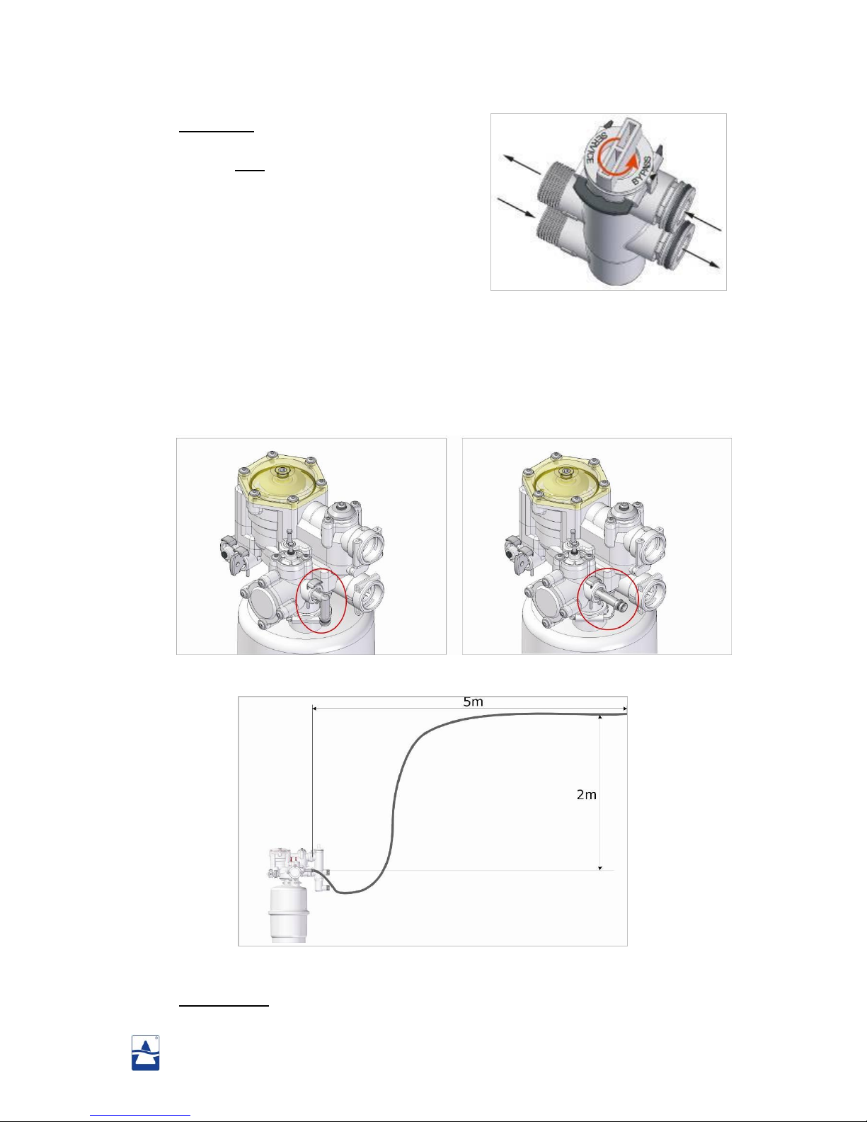
Use a hex key number 5 to turn the program disk (PRG) manually.
T
u
r
n
P
R
G
c
o
u
n
ter clockwise until it is in above position. When the arrow and the
small line on the transparent cover reach the area marked by “B”
(brining), the regeneration will start. Immediately, the PRG will drop
down a little (you will be able to see and hear this). “R” stands for
refill (refilling the container with water at the end of the
regeneration stage). To make sure the softener is in regeneration,
there should be a small water flow to the drain, and the water level
in the container should drop.
5.6.2.
Let regeneration perform until it stops automatically. The estimated
time is approx. 12 minutes. When regeneration has stopped, no
more water flows to the drain. This is a clear indication that the
regeneration stage is over.
5.6.3.
Open a tap behind the softener for several minutes to allow residual
water to be flushed from the tubing.
5.6.4.
Check outgoing hardness with a “hardness test kit” (not supplied by
Delta). Adjust blending if necessary.
B
R
B
R
R
E
E
C
V
I
S
R
E
E
C
V
I
S

DELTA WATER ENGINEERING V05/2009/P10
5.7. Place both lids on the container. First the valve house cover; make
sure the connections fit in the large opening and the drain in the
small opening. Then place the front lid. For future salt refills, only
the front lid has to be removed.
Don’t forget to connect the overflow to the drain.

DELTA WATER ENGINEERING V05/2009/P11
REMARKS:
It is recommended that a water softener is installed by a professional. Although the
DELTA softener is probably the easiest and safest softener on the market, it is imperative
that all necessary precautions are taken and local legislation is followed.
This installation guide is written to help the professional installer keeping in mind that
this person has essential knowledge about hydraulic softeners and domestic plumbing.
Proper working of the softener will be determined by proper installation.
An annual control of your Delta softener will guarantee optimal functioning and a long
operating life.
The DELTA WATER ENGINEERING team is proud of its achievement in having
provided in what we believe to be the best softener available today.
Moreover, we are proud to have you as a customer. We will do our utmost to
deserve your trust.
DELTA WATER ENGINEERING
Waesdonckstraat 1
2640 Mortsel
Tel: +32(0)32195070
Fax: +32(0)32899320
BTW: BE 863.958.709
info@deltawatersystems.com
sales@deltawatersystems.com
Table of contents
Popular Water Dispenser manuals by other brands

Winterhalter
Winterhalter MonoMatik 3 operating instructions

Honeywell
Honeywell HWDT-620W owner's manual

DS Services of America
DS Services of America 200K Series How to Clean

Everpure
Everpure CGS-22 Specifications

Franke
Franke KEP3CP instructions

East Midlands Water Company
East Midlands Water Company SUMO manual

Emerson
Emerson InSinkErator indulge Series owner's manual

InSinkErator
InSinkErator Indulge Tuscan F-GN2215 Specifications

Elkay
Elkay Space-ette FD700-3 1J Series Installation, care & use manual

Halsey Taylor
Halsey Taylor HTVEE Series owner's manual

Orbegozo
Orbegozo DA 5650 instruction manual

Eclipse
Eclipse BoilerMag Installation and servicing instructions