DeltaLab EFFECTRON II User manual
OWNER'S MANUAL
ADM 256/ADM 1024
DeltaLab
*
BE,E CF qVIEDTXS
PreE
Frcf,ifIPAliEroLrILIliE. . . . . . . . . . . . . . o . . . . . . .l
REARPANEtCfIffTINE... . .. .... . . . o . . .. ! . ..2
rNrlcDuef[Gl. . . . . . . . . . . . . . . . . . . . . . . . .3
crRcurrDEscR[Pr[oN. . . . . . . . . . . . . . . . . . . . . .3
BIOCKDIAGRAII. . . . . . . . . . . . . . . . . . r . . . .4
IMTIALSEIUP. . . . . . r r o . . . o r r o r . . . . . . . .8
APPLICATfONE. . . . . . . . . . o . . . . . . . . . . . o . .9
1. SIRAIGET DEf,.Ay . . . . . . . . . . t . . . . . . . . . 9
d. DTSCREIE EfTnS, S:fAPBAffi . . . . . . . . . . r . .'I0
b. muBLrl\G, rIIrcKEr{r}G, BmADE}rrIW . . . . . . . . .11
c. PRTREVERBDH.Ay. . . , . . . o . . . . . . . . .11
d. gAAS-Ffmf il.'IAGESIIIFTIIiG. .... ... . . ..12
2. FEmBACKffiSIt:pBgDE[-af,S. .,.. t r . .. . . .. .12
El. @MBFrLlmniG. . . . . . . . t . . . . . . . . .12
b. FIAIiEIIiG . . . . . . . . o . o . . . . . . . . r .13
c. FIAIGIIGWIIIIFmBACI(. . . . . . . . . . . . ..13
d. FffiDBACK PIIASE rI{VmSrON . . . . . . . . . . . . .14
€. ruNm RESI{AilEE. . . . . . . . . . . . . . . . . .I4
, 3. EEEDBAffi OF IONE DEAyS. . . . . . . . . . . . . . . .15
a. 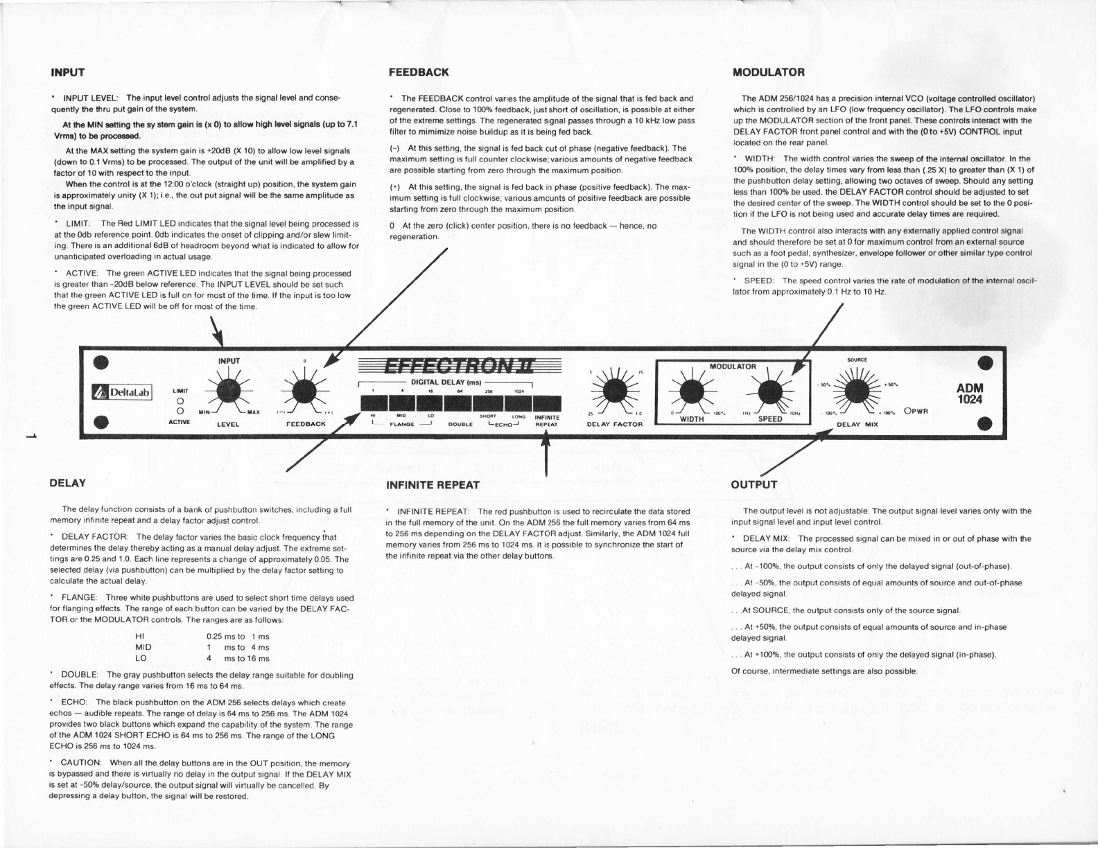
'T{PUT
' INPUT LEVEL: Tha input loEl control adiusts tha signal let€l ard conse'
quently ihs thru put gain ol th€ systom.
Al tho MIN $nirlg ltp.y slorn grln B (x 0) to sllow high lml lign ls (up to 7.1
Vrmr) to b6 pro6ad.
Al lhe MAX stting tho systsm gain is +20d8 (X 10) to allow low lewl signsls
(down to 0.1 Vrms) lo bo prm8sad. Ths output ot the unit will bo amplilisd by a
lactor o, l0 with resp€ct lo ths inpul.
Wh6n ths control is at tho 12:00 o'clock (straighl up) position, the system gsin
is approximately uniry (X l); i.e., tho oul pul signal will b€ the smo amplitude as
the input signal.
' LIMIT: The Bed LIMIT LED indicates that the signal level being pr@essed is
at the odb Gleence poinl. odb indicaies the onset ot clipping ard/or slew limit-
ing. Thore is an additionsl 6tB ot headroom b€yond what is indicated to allow for
unanticipatad overloading in aclual usge.
' ACTIVE: The gEn ACTIVE LEO indicales thal the signal being prGessd
is greater lhan -20d8 below retersnce. The INPUT LEVEL should be set such
that the grmn ACTIVE LED is tull on for most of the lime. lf the input is too low
lhe green ACTIVE LED will be otf tor most ot the time.
DELAY
The delay lunclion consists of a bank of pushbutton switches. including a lull
memory inlinite repeat and a delay lactor adjusl control.
' DELAY FACTOR: The delay factor varies the basic ctock frequency ihat
determines the delay thereby acting as a manual delay adjust. The extreme set-
tings are 0.25 and 1.0. Each line represnts a change ol approximately 0.05. The
*lected delay (via pushbulton) can be multiplied by ihe delay lactor stting to
calculate the actual delay.
' FLANGE: Three white pushbuttons are usd to select short time delays used
tor flanging ertects. The range ol each button can be varied by the DELAY FAC-
TOR or the MOOULATOFI controls. The ranges are as lollows:
Hl 0.25 ms to 1 ms
MID 1 msto 4ms
LO 4 mstol6ms
' DOUBLE: The gray pushbution selecls the delay range suitable lor doubling
etfects. The delay range varies lrom 16 ms to 64 ms.
' ECHO: The black pushbutton on the ADM 256 selects delays which create
echos - audible repeats. The range ol delay is 64 ms lo 256 ms. The ADM 1024
provides two black bullons which expand the Gpability ol the system. The range
o, the ADM 1024 SHORT ECHO is 64 ms to 256 ms. The range of the LONG
ECHO is 256 ms to 1024 ms.
' CAUTION: When all the delay buttons are in the OUT position, the memory
is bypased and there is virtually no delay in the ouiput signal It the OELAY MtX
is sl at -50% delay/source. the output signal will virtually be emelled. By
depre$in9 a delay button, ihe signal will b€ restored.
FEEDBACK
' Ihe FEEOBACK conirol varies the amplitude of the signal that is ted back ard
regeneraled. Close to 'l0O% f*dback, just shorl of o$illation, is possiblo at eilhet
o, the extreme settings. The regeneratod signal pass lhrough a 10 kllz low pass
lilter to mimimize noise buildup as it is being fed back.
(-) At this stting. the signal is ted back oui o, phas (negative f*dback). The
maximum stting is full counter cl@kwi*; various amounts of negalive ,eedback
are possible starting rrom zero through ihe maximum posilion.
(+) Al this setting, the signal is fed back in phas (positive fedback). The max-
imum setting is tull clockwise; various amounls of posilive feedback are possible
starting from zero through the maximum position.
0 At the aro (click) center position, there is no fedback - hence, no
regeneration.
MODULATOR
The ADM 256/1024 has a precision inlernal VCO (voltage controlled oscillelor)
which is cmtrolled by an LFO (low lrequency o$illator). The LFO cmlrols make
up the MODULATOR *clion ol the ,ront panel. Thes controls intemct with the
DELAY FACTOH f ront parel control and with tho (0 to +5V) CONTROL input
locat€d on the rear panel.
' WIDTH: The width control wries the srvesp of th€ intemal osillator. ln the
10O9o posilion, the delay limes vary from less ihan (.25 X) to groater than (X l) of
the pushbution delay stting, allowing two Glaves ot swoep. Should any satting
less than 1009! be used, the DELAY FACTOR control should be adiusted to set
the desired center ol the swep. The WIDTH control should be st to the 0 pGi-
tion il the LFO is not being usd and acurate delay tires are required.
The wIDTH conlrol also interacls wilh any sxternally applied control signal
and should therefore be st at 0 for maximum control lrom an external source
such as a foot pedal, synlhesizer, envelope followor or other similar type control
signal in the (0 lo +5V) range.
' SPEEDT The speed control varies lhe rale of modulation o, the inlemal oscil-
lator from approximatelv 0.1 Hz to 10 Hz.
OUTPUT
The output level is not adjustable. The output signal level varies only with lhe
input signal level and input level conlrol.
' DELAY MIX: The processed signal can be mixed in or out of pha* with the
source via the delay mix control.
. . . At -1009o, lhe output coosists o, only the delayed signal (out-ol-phas€).
. . At -50o/o. the outpul consists o, equal amounts of source and out-of-phas
delayed signal.
. . .At SOUBCE, the output consists only of the source signal.
. . . At 150%, the output consisls ot equal amounls ol surce and in-pha*
delayed signal.
. . . At +1000/0, ihe oulput consists of only the delayed signal (in-phas).
Ol cour*, intermediale settings are also po$ible.
INFINITE REPEAT
' INFINITE REPEAT: The red pushbutton is used to recirculate the data stored
in the ,ull memory ol the unit. On lhe ADM 256 the ,ull memory varies from 64 ms
to 256 ms depending on the OELAY FACTOR adjust. Similarly. the ADM 1024 full
msmory varies from 256 ms to 1 024 ms. lt is possible to synchronize the start o,
the inlinite repeat via the other delay buttons.
fur.* #
O acnw LEvEt- FEEDBA.( ,#: :**"".*
o
ADM
1t24
o
#"*x
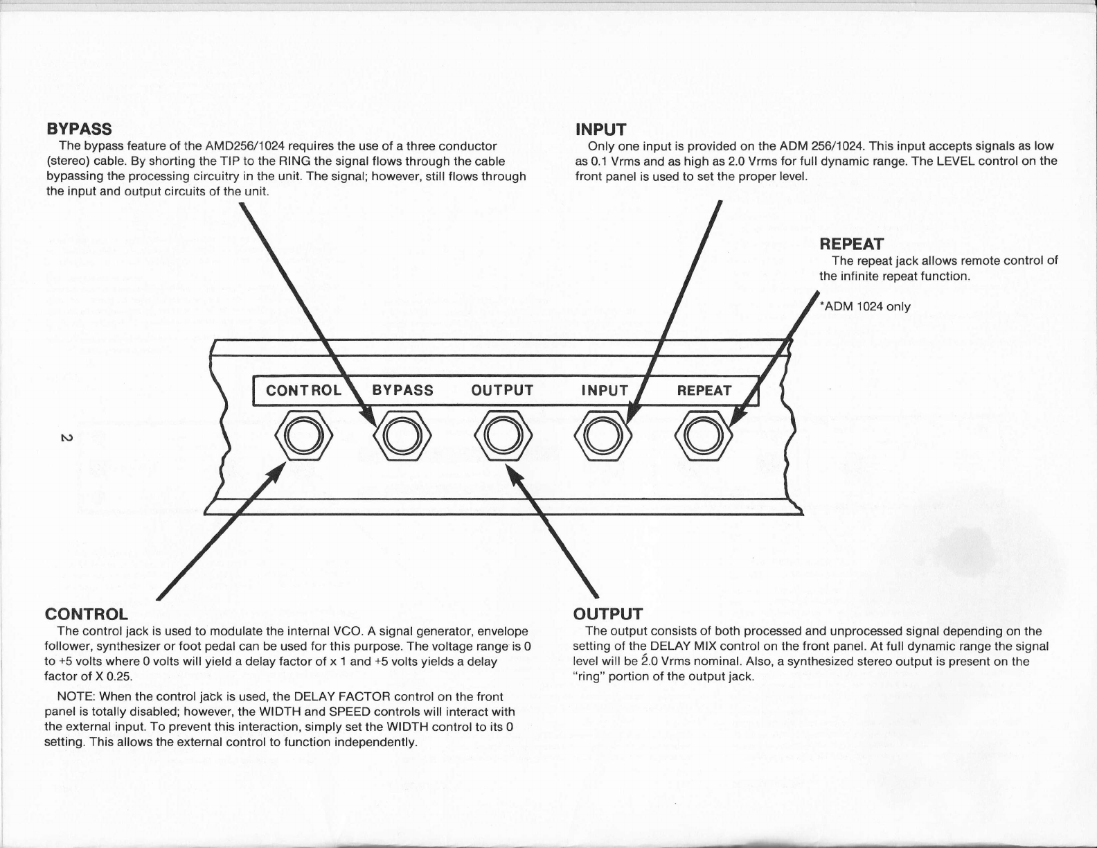
BYPASS
The bypass feature of the AMD256/1A24 requires the use ol a three conductor
(stereo) cable. By shorting the TIP to the RING the signal flows through the cable
bypassing the processing circuitry in the unit. The signal; however, still flows through
the input and output circuits of the unit.
INPUT
Only one input is provided on the ADM 256/1024. This input accepts signals as low
as 0.1 Vrms and as high as 2.0 Vrms for full dynamic range. The LEVEL control on the
front panel is used to set the proper level.
REPEAT
The repeat jack allows remote control of
the infinite repeat function.
.ADM 1024 only
OUTPUT
The output consists ol both processed and unprocessed signal depending on the
setting of the DELAY MIX control on the front panel. At full dynamic range the signal
level will be 2.0 Vrms nominal. Also, a synthesized stereo output is present on the
"ring" portion of the output jack.
CONTROL
The control jack is used to modulate the internal VCO. A signal generator, envelope
follower, synthesizer or foot pedal can be used for this purpose. The voltage range is 0
to +5 volts where 0 volts will yield a delay factor of x 'l and +5 volts yields a delay
factor of X 0.25.
NOTE: When the control jack is used, the DELAY FACTOR control on the front
panel is totally disabled; however, the WIDTH and SPEED controls will interact with
the external input. To prevent this interaction, simply set the WIDTH control to its 0
setting. This allows the external control to function independently.
BYPASS OUTPUT INPUT
INTRODUCTION
tm
Itre EFFETRON fI is an qdated version of ttre original EFTaEON. It is a
studio quality, speciaI effects processor designed for ttre trnrforming
m,rsician. I?re qdates include suggestions received from ttre nwry satisfied
oyners of EEFETBOilIS...irTg)roved inpt stage, stereo outSuts and erren a
rernote Infinite Retrnat jack on ttre ADll L024. You can rest assured ttrat yorr
EEFETRON II will becore one of ttre rost irgnrtant congnnents in lour total
sound slctern.
CIRCUIT DESCRIPTION
EVen if you are not tecnically inclined, v€ urge 1ou to read ttris chapter.
A basic understanding of how signals are processed ttrrough the EFFECIRON If
vril1 make it easier to predict the effect of control settings and easier to
plan control settings to achieve desired sound effects. BrtT first a word
about ttre ngiuts" of the design.
Orly the latest technology has been used in ttre design of ttre EEFEIBON II.
this aSplies to conqnnents as well as circuit design.
For exarple:
1. ltre po,v'er sulp1y uses a toroidal transforner to minimize hum and
eliminate stray rngnetic fields.
2. Ihe digital nrenory consists of bottr 15K and ttre new 54K (used
in the ADM 1024) Dynamic MMrs (Random Access Merory).
3. A11 digital integrated circuits are CI'DS for lovr [D$er.
4. All analog integrated circuits consist of both biplar and lOS
technology for both lovr noise and reliability.
5. Precision resistors (+/-1-*l are used in critical circuits to
insure retrnatability.
6. Ihe printed circuit board is standard miI spc G-10 materiaL.
7. A11 ottrer corponents such as Sntentioreters, sritches, etc.7
have been sirnilarly selected for optinun qrality and reliabiJ-ity.
8. For roadability, ttre chassis is all steel wittr an aluninum front
panel.
Ihe circuit design incor;nrates DEI,TAIABIs trntented Adaptive Delta
!{odulation (AUt{) technology regarded by audio professionals as ttre rpst
natural and cleanest sounding digital encoding technique. A detailed
orplanation of ttre circuit designr vid the block diagram shorn, follows:

LriilT oy' R
ACTIVEO,/ G
INFINITE REPEAT
(FRONT)
o
t:?
EFFECTRON'" ll aucr lxagrarn ADU 2s6 / 1024
x.Zli
x 1.0 lF
DELAY
FACTOR
+5v
'ADM 10i14 only
DELAY[mSl
EIr:l3r:€
clock [250kHz - 1
CONTROL
ltre iryut audio signal is fed into ttre EFFECIBON II via ttre INPUI ptrone jack
located on ttre rear paneI. ltris signal is routed through an intrut arplifier
stage to protrnrly set the otrnrating signal 1evel via ttre INzuI LEVEI, control
located on the front panel. Ihe INPIIT tE\rH, control also sets the gain of
the total slmtern (ttrere is no conpensating antput leveI control). The
minimrm input rrcltage is 0.1 Vrms.
Ihe correct otrnrating 1eve1 is set by observing the green ACTIVE rpnitor and
the red LIMIT npnitor located on the front paneI. llhese LDrs npnitor ttre
level as seen by the encoding circuits. For maxfurum dlznamic range, the
active LD should be full-on wittr a rare flashing of ttre LI}IIT LD during
pak trnssages in ttre audio inptrt.
Grce the proper inp:t leve1 has been set, the audio signal is directed to a
pre-enphasis circuit to pre-condition ttre signal before ttre actual Analog-
to-Digital conversion takes place.
After pre-enptrasis, ttre pre-conditioned signal is ncxc sent to tJre AZb
encoder to be converted to a digital signal. It is here ttrat DELTNAB holds
all the aces. Itre Analog-to-Digital encoding schenre is unique. A carefully
designed Adaptive Delta lbdulator converts ttre audio signal by analyzing
both the value and s1ery rate of ttre signal. ftre resu]t is ttre rpst accurate
digital representation of the audio signal trnssible over the fulI dlnanic
range.
IGxt, the digital signal representing ttre audio is stored in ttre digital
IIEIIpry. Access to this rrErnory is via ttre trushbutton switches located on ttre
front panel. [Jtrnn selection of a given deIay, as indicated by the
lushbutton, the digital signal is extracted frqn ttre rerpry and sent to ttre
Digital-to-Analog decoder. Ir1cte ttrat ttre f;7D, the remory and ttre D/A are
slznchronized to a conmon clock to insure the protrnr addressing of ttre renory
banks and to provide ttre sanpling rate for the A7b encoder and D/A decoder.
ftre O/a decoder is ttre perfect conplinent of the Adaptive Delta ttlodulation
encoder. At the p/a output, the signal is sent to an inverting arnplifier
and furttrer directed to bottr the FEDBACK and DEIAY MD( controls located on
the front paneI.
Ihe DEAY [vlD( control is a center tapped trntenticrneter, i.e., the
unprocessed inprt signal is alplied at ttre center tap and each phase of the
delayed signal is alplied at ttre extreme terminals. As such, a single
control is all ttrat is necessary to mix ttre processed signal (either phase)
with the input (source) signal.
Ihe final mix is then de-erphasized to restore ttre audio to its protEr
leve1s. ftre outtrxrt is available at the GIIP[}T phone jack on ttre rear-paneI.
Ihe final audio signal available at ttre Q}IPUT jack is furttrer processed by
a trntented phase shift circuit to simulate stereo output. ltris circuit
keeps the lovr frequencies in tr*rase t*rile providing a controlled anount of
phase shift for mid and high frequencies. Itre result is a very realistic
form of simulated stereo signal. The sinulated stereo output is available
by using both the tip and ring of ttre OIIIPIIT jack.

Meamvlnile, back at ttre FEEDBACX control, the processed audio (delayed
signal) is fed back to a surTrning point and mixed wittr ttre incoming signals
at ttre ArzD converter input. The FEDBACK control, like the DE.AY !tD(
control is a center ta5ryed Sntentioreter. fhe center tap is grounded so
ttrat ttrere will be no feedback l*ren ttre control is on ttre center Snsition.
Again, like the DEIAY MD( control, bottr phases of ttre processed audio are
available at each extrene terminal. llherefore, only one FEEDBACK control is
used for both positive and negative feedback.
Before being mixed wittr ttre pre-conditioned inprt, the feedback signal is
filtered via a L2kHz low trnss filter to create a rpre natural and pleasant
sounding echo retrnat as well as to keep ttre noise level from hrilding up
when nnximum feedback is used.
A digital feedback Inth exists from ttre nernory outtrut to ttre rerpry inp:t
constitutjng an infinite retrnat c1rc1e. B1r depressing the red INFIMTE
REPEAT Sush button to the 'in" Snsition, the digital rerory is recirculated
i:rdefinitely. ftre resulting audio out is an echo ttrat never dies out. Itl
ttre ADIvI 256, ttris echo is 256 msec (L/4 of a second) at ttre maxfun:m setting
of the DEIAY FACTOR control: Ihis sare echo is over a fuII second (1024
rcec) on ttre ADM 1024. To defeat ttre repeat function, sinply trush ttre red
IIEINIIIE REPEAT button so ttrat is is returned to ttre 'outtr trnsition.
I'ltren the INFINIIE RPEAT button is in the 'outn trnsition, 1ou have ttre
option of using the rear panel INFIMIE REFEAT jack (AEM 1024 only). By
using a mono ptrone p1t4J, 1ou will nov be able to activate the jnfinite
reSnat function via a foot svitch. As shovnr beIow, by shorting the tip to
the sleeve, the digital rrerrpry will be recirculated indefinitely. lto defeat
this function, you sinply discoru:ect ttre tip from the sleeve.
MONO CABLE
Switch Close = lnlinite Repeat
Switch Open = Normal
l[tre last Snssible signal path is the BPASS wtrich requres ttre use of a
stereo (three conductor cable) tr*rone plug to be connected to ttre HIPA.SS jack
located on the rear panel. B1r shorting ttre TIP to ttre RllG, the pre-
conditioned audio is directly routed ttrrough ttre cable and back to the de-
enphasizing circuitry in ttre unit to b14nss all digital and feedback signal
paths. A sirple schenB for doing ttris is shovn on ttre next 5nge.
6

BYPASS JACK
Stereo Cable
Switch Closed = Bypass
Switch Open = Normal
Ihe foltowing functions are not in the signal path, but are useci to control
the basic bit rate clock to create strEcial effects other than those that
resul-t by sinple feedback. Ihere are three front panel controls whose
function is to provide a control rroltage into the precision Voltage
Controlled Oscillator (WO) used as the digital bit rate and sanpling clock.
For exanple, a control voltage of 0 to 5 rrcIts will vary ttre clock for 250
kHz to 1 MHz wtrich results in a four to one (two octave) range.
Setting ttre WIUffi control, located on the front panel, in ttre 0 position,
ttre DEISY FACIOR control (a1so located on ttre front panel) provides ttre
required voltage as shovnr below in ttre block diagram. WLren an external
signal is atrplied to ttre @IVIROL jack located on the rear paneI, the DEIAY
FACTOR is disabled.
CONTROL JACK
ft oro+Sv
IL_f."
The WIII{III control is used in conjunction with ttre SPEED control located on
ttre front panel to apply a Iow Frequency Oscillating (tFO) rzoltage to the
\rcO inprt. the L,FO is a sinusoid wtrose frequency is controlled by the SPED
control. The I{U}IH control determines ttre amplitude fed into the \DO. It
can be seen that jnternediate settings of thre IfiUIH control wil-] cause a mix
of bottr the DSAY FACIOR setting and t-lTe LFO outtrut. A1so, l*ren a rcltage
is applied to the external @NIROL jack, ttre WIDIII will likewise mix
internal LtO settings with ttre external control voltage -- all of tftich
makes for interesting effects. Ibte ttrat ttre WIEIIH control provides a
greater than 4-to-1 s*eep range.
Ihe EFFECIBON II is basically a simple to understand device, but because of
its sinplicity it is a very trnwerful effects tool.

INITIAL SET UP
Drc to its simplicity, there are no strncial setup rules ttrat need to be
observed. Ttre only situation ttrat can cause annoyance is if the INFIMTE
RPEAT button is in the 'in" trnsition wtren the unit is first plugged into
the AC trDwer line. Usually the LIMIT LED will light up to indicate this
condition. SJnply Srrsh tkre RD button to ttre uout' trnsition and all will
clear up.
V{e do; however, recoruend ttre following be used as a starting point until
you familiarize yourself with each control:
INPUT LEVEI,
FEEDBACK
DErAY (BrrmONS)
INFIMTE REPEAT
DELAY FACTOR
WIUITI
SPED
DETAY IvIIX
!lIN: fuI1 counter clockwise
0; center trnsition
Start with GRAY button ninrl
B:tton nout'
X1 position; fu1l clockwise
0; fuII cou:rter clockwise
0.1Hzi fuIl counter clockwise
SOIIRCE; Center position
The INPLE LEVEL can now be adjusted for proIEr 1evel via ttre LED nonitors.
A11 other functions can be varied at will to create the various effects.
liUTE: IN ORDM, 10 INSURE RE,ISBILTIY AI\ID IOIiG LIFE E,Y PREVE}IIII\E FAII.,URES
DtE IO UNIrcESSARY IEffiDCL SmK, r.8.7 (PI AllD @ID \fARIATIOI\S), IEE
EFFETBON II mES IUI HAVE AII OFF/ON S{rTCH. lEE AVERAGE PoHER @tIStfiPfION
IS LESS IBAN 5 IBTIS; IIIIS Sm]tD IUI AEEET lEE OPRATIIG rcOD0ry 0F YCIIR
IUIAL SotnD SySrEU.

APPLICATIONS
Vlhile the EFFECIRON II is caSnble of providing a very large array of
effects, they all fa1I into the basic categories (or corbination of these)
outlined below:
1, SIRATGE DtrAy
d. DISCREIB rcfDs, STAPBACK
b. DOUBLM, TIIICKENII\E, BROADENIIiG
C. PRE.REVMB DEI,AY
d. IIAAS-EF.FM IIiAGE SHIHITI\G
2. FEmBACK QE SIXoRT DELAyS
€1. @l{B FILIF,RII.IG
b. FIAIGI}G
C. FIATGI}G WITTI FEDBACK
d. FEMBACK PHASE II$/mSION
€. IUNM RESOIiBNCE
3. FEmBACK 8F rOlC DETAyS
d. IVIT]LTIPLE ECIOS
4. TIME BASE }ICDTIIATION
EI. MANUAL PIrcH SHIFTII\re
b. VIBRAIO, ALIIOIvIATIC PIrcH SI'IEEPIIG
5. INFINITE REPEAT
1. SIRAIG{I DEI,AE
Sound travels in air at a finite sSned - approxirnately 340 reters per
second (1100 feet per second), or about one foot trnr rnillisecond -- and rwry
of ttre uses of a digital delay processor involve t}re controlled electronic
recreation of effects which occur in acoustics due to this finite sped.
For instancer for practical reasons, vocal-s and instrunentals are usually
recorded in a nearly anechoic fashion by close-miking in an acoustically
absorptive studio, but this soretfures yields an anenic, uninteresting sound.
!{henever lre hear vocal instrunental sounds in a living room or concert
envirorurent, the dry sound is accompanied by reflections off nearby vn11s,
floor and furniture. Itrese early reflections accorrgEnying the direct sound
- slightly delayed because of ttreir longer airtruttr - add aptrnrent volure
and fullness and thus enrich ttre character of ttre sound.
9

:
ltre sulcjective effect of reflections (detayed replicas of an original sound)
depends on the lengttr of the delay as follows:
- Single or nultiple delays up to about 40 milliseconds after the
direct sound alters ttre atr4nrent character of quality, but are not perceived
separately. Ilpically, they add ttre sort of nfullnessn and body wttich a
voice has in a living room, but lacks when heard outdoors. lhey are calIed
"earlyn reflections.
- A single delay within about 40 milliseconds and having the sane
volune Ieve1 as the direct sound, produces an effect souettring like that
heard l*ren a solo voice is replaced by two identical voices singing in
unison. Ttris is cal1ed "dorrbIing".
- A single delay longer ttran 40 to 50 milliseconds starts to break
away from the original sound and be perceived as an echo.
- A longer deIay, i.e.7 over 100 mS and sr:bstantially lower in 1evel
ttran ttre original sound, is heard as a nslatrback" echo like ttrat from ttre
rear waIl of a cathedral or other large space. Of course, to be
acoustically auttrentic, any delay must be lo*er in leve1 ttran the direct
sound. A delay rtrich is sulcstantially louder than the dry sound Wilt be
perceived as the original, and the original sound will a54nar to be a false
pre-echo.
- ReSnated delays at intervals greater than 50 milliseconds are
trnrceived sinply as multiple echos. If ttre trnttern of nultiple de1a1c
becones more complex with dozens or hundreds of echos per second in a
Snttern which fades progressively away into inaudibility, ttren ttre echos are
trnrceived as a single continuous sound - reverberation. Acoustically
auttrentic reverberation includes sore nearly" reflections beyond 100 ffi
becoming progressively closer in strncing as ttrey fade away. If ttre
reflections are slnced at unfiform intervals in tfure (e,9., a sinple string
of echos 40 nS agnrt), the reverberation of transient sounds acquires a
chattering gality known as 'flutter echor, or "hard reverb'.
a. DIS(REIE rcI0S, STAPBACK
Feed a signal into ttre EFFFIBOI{ IIrs inSutr Sush ttre echo button
and ttren increase ttre DEIAY FACIOR until ttre delay tine is long
enough to be trnrceived as a discrete echo. While ttris echo can be
mixed directly with the dry sound, a more interesting result is
usually obtained by panning ttre echo elsewhere in the stereo image
with a stereo mixer; i.e.7 place ttre dry sound on ttre left and the
echo otr4nsite it on the right. Itre echo usually should be a bit
lower in leve1 than the dry source.
Itris left-right echo bouncing effect is lnrticularly useful wittr a
regular drum beat or a tr,ro-note guitar figure that is used to set
the beat. B1r varying the DELAY FAC:IIOR, lotl IIBy be able to
slznchronize ttre echo interval to match the rhythm of ttre rmsic so
that ttre source and its echo faIl on alternate beats.
10
b.
If the delay is 10 to 20 dB lower in 1evel than the source, it
will be trnrceived as an echo .- especially if it is placed in the
otr4nsite channel. ff ttre delay is reproduced at ttre sane level as
the source, it will be identified as a repeat rattrer ttran as an
echo such as from a distant waII or canlon.
DOUBLII{G, $TICKENI}re, BROADENII\IG
fip voices singing together, or a single voice wtrich is double-
tracked (overdubbed to accorpany its previously recorded self)
produce a conbined sound r*rich is richer and rnore interesting ttran
sinply turning up a single vocal track 3 dB in leveI. Ote reason
is that ttre trrc separate voices are never recorded in exactly
precise slmchronisrn. Ihe waveform of one is usually a few
milliseconds atread or behind ttre other despite ttre npst careful of
rehearsals.
Itris effect can be simulated with any single source sinply by
delaying it by 16 to 64 milliseconds and mixing ttre delayed signal
with ttre original at equal leveIs. Ttris is caIled doubling. It
thickens the texture producing a rnore "fu11-bodied'r sound vitrile it
increases ttre atr4nrent loudness without significantly raising W
reter Ievels. It is trnrticularly useful for adding strength and
character to a thin-sounding vocaI.
You should experirnent with the legnth of ttre delays used for
doubling. With delays in ttre 16-20 rS range, the sound rqnains
relatively tight and focused. Delays of 30-40 nS produce a rpre
obvious broadening. Doubling with delays shorter ttran about 15 mS
is not reconnended because of ttre risk of coloration due to corb
filtering. If you extend thre delay beyond about 40 mS it may be
heard as a distinct echo.
Itris process simulates two vocal tracks with a sna11, but constant
delay between them. Of course, l*ren real voices are recorded or
overdulcbed, ttrey have varying sna11 differences between them. So,
to make its doubling seem nore realistic, use ttre IIffiUIATOR to
continuously vary ttre de1ay. Ihe action nu.rst be sulctle so as to
avoid audible pitch wobble. Setting the widttr and speed controls
both to between 7:00 and 9:00 orclock, usually produces a
pleasingly realistic doubling effect wittr no audi"ble side effects.
PRE.REVMB DEIAY
Authentic acoustic reverberation in a large space requires rnany
dozens of milliseconds to buildup, Brt, in nany studio reverb
units (spring, plate or acoustic chanrber) an outptrt signal begins
to atr4nar very rapidly after ttre onset of ttre inpt signal. Ihe
subjective trnrfornnnce of reverberators is usually inproved by
delaying the signal fed to them. Both the AE[4 256 and ttre AD['I
1024 can provide this deIay. ftle delays used for doubling often
serve as pre-reverb delays.
C.
II

In a concert environnrent, the listener hears the direct sound from
ttre perfonner, folloued by trearlyn reflections from the floor and
wa1ls of the stage and finally the reverberation ourprised of long
delap as sound is reflected anong ttre walls of ttre auditoriurn.
When using a reverb slctem to process dry studio sound, pre-reverb
delay can also serve as ttre 'early' stage-area reflections, sinply
by including thern in ttre mix.
d. IIAAS-EFFFT IMA@ SHIFTIIiG
ftre ear has an integration tire of about 40 mS. ff a sound is
heard from one direction and the sane sound also arrives at a
later tine from another direction, the second arrival will not be
heard at all if the interval betr,ueen the two arrivals is less ttran
40 mS. Ihe later arriving sound may even be several dB higher in
level than its earlier counte4nrt; neverttreless, the ear will
hear both sounds as a single louder sound located in the direction
of the first arrival. ftris is ttre precedence effect - or ltraas
effect - and it can be used to stabilize innges in a stereo sourd
f ieId.
For exarple, if a signal is recorded in both channels,at identical
1eve1s, the feed to the right channel is delayed, tkren the
sound will be trnrceived as originating exclusively in the left
channel. In principle, the delay to ttre otr4nsite channel nray be
anything from l rnS to 40 mS. But, long delays carry the risk ttrat
sore listeners my begin to Snrceive ttre delayed sounds as an
echo; and if ttre delay is under 10-15 mS coloration due to corb
filtering could becore a problem if ttre two channels are later
mixed together (for AtlI broadcast, for instance). A delay
of around 20 mS usually turns out to be optimum for Haas-effect
image panning.
It is trnssible to keep the signal level constant in both channels
and cause the innge to jump back and forth from left to right by
swalping the delayed and undelayed signals by panning the rnixer.
2. FEDBACK CIE StrOR[ DEI,ASS
By using the feedback control, the delayed signal is fed back and mixed with
the incoming audio signal and thren the congnsite signal is encoded and read
into the digital delay circuits. Itre strength and tonal Erality of ttre
feedback rnay be adjusted by the user. Ihe maxinnrm feedback gain is less
than unityi tttus, like a real sound reflecting off any surface, the recycled
signal is at least a little weaker than ttre original, drld as ttre sound is
retrntitively recycled through ttre system, it gradually fades away.
d. CClvlB FILtERIIG
Whenever any original sound and a delayed version of itself are
mixed together, the two sounds are mutually reinforced at sone
frequencies and tend to nnrtually cancel at other frequencies.
Itris rccurs in an electronic delay line and it also is a comrpn
acoustic tr*renorenon both in recording (v.ltrere the mike picks up
12
b.
both the direct sound and a reflected sound from the floorr waIl
or music stand) and in plalback (wtrere a loudspeakerrs direct
sound conbines in ttre air with reflections off room boundaries and
furnishings). Ihis pattern of alternating reinforcenent and
cancellation causes an audible coloration of the sound.
t\rc things are noterrorttry. One is ttrat the reinforcenents and
cancellations occur at hanrpnically-related frequencies. ftre
other is that ttre trnttern of peaks and dips can be variedT i.e.7
tuned, just by varying ttre delay tfure. In alrost all nornal vocal
and musical sounds, most of ttre energy is found at fundanental
frequencies and ttreir harmonic overtones. By varying ttre delay
tire of a delay-and-mix circuit, we can easily but dramatically
alter the overtone structure and ttre tonal quality of any steady
sound. Ihe precise delay tfunes and unusually flat frequency
res[pnse of ttre ffFECIRON II make it ideal for corb filtering on
demand.
FIA}GIIiG
If the unit is setup to produce conb filtering and ttren the delay
tfure is snoothly varied, the Snttern of peaks and nu11s will shift
in frequency. lbdulate the delay tiue rapidly and the trnttern of
trnaks and nu11s wi}l sweep rapidly up and dovm the frequency
spectrum trnssing in and out of slznchronization with the
frequencies of musical signals and ttreir overtones. Select
relatively short delays so ttrat the strncing of ttre nul1s
corresgnnds to ttrat of musical. harrnonics. A.s ttre delay is swept,
at one rorent, ttre odd-nwlcered harronics are enhanced by 6 dB -
a rnorent later, tte harmonic structure of ttrat note is sliding
into alignrent with ttre harnpnic overtones of a different note.
Ihis sweeping, shifting change is calIed "flanging'.
Iro achieve iL, one need only setup ttre delay and mixing as
reE:ired for corb filtering and then activate ttre modulator
to sweep the delay tine up and down. Typically the rpdulator
IflUIH is set at maxinum in order to produce a broad srreep and the
npdulator SPED is set at a npdest value (e.9., between 7:00 and
9:00 orclock) so that ttre conb filter stneeps up and down every few
seconds. A high setting of the npdulator SPEED would sreep the
notch trnttern over ttre musical spectrum too rapidly for the
changing harnpnic structure of the music to be heard and might
also cause audible pitch vrcbble of ttre musical signal itself. You
strould exlnrfurent to find ttre settings of DELAY, WIDIH, SPED and
mixing ratio which yield interesting flanging effects with
various vocal and instrumental sounds. rn general, higher-pitched
sounds work best with shorter delays.
FI,A}GIIG WIIIT FEMBACK
rlixing the dry and delayed signals at approxinately ttre sare level
causes corb filtering (a trnttern of nu11s and peaks in frequency
restrrcnse). l,lodulation of the delay tire causes ttre trnttern of
13
C.
d.
nulls and 1reaks to sneep ttrrough the nnrsical strnctrum producing
'flangingn.
A stronger, richer flange is reproduced by using maximrm feedback
to create a chain of closely-sSnced de1a1e v*rose uniform spacirg
strartrnns and strengthens ttre corb filter peak and nu11s. Select
short delays such as I or 4 mS and set ttre FEDBACK near the
maximum setting, either trnsitive or negative. Fina1ly, npdulate
ttre delay by setting npdulator WIum at maxirmm and Spnm betueen
7:00 orclock (for a slow flange) and 12:00 orclock (for a fast
flange). Iibte ttrat is is ingnrtant to use near maxim.un feedback
so that each successive recycled delay is at nearly the sane
strengttr as its predecessor, yielding the strongest
reinforcerent/cancellation pattern. Itre flange can be varied, of
course, by selecting different front pnel deIa1e. If the V{IUI}I
control is set less than naximum, the DEIAV FACTIOR can be used
to alter ttre delays and thus shift ttre frequencies of ttre corb-
filter Snttern. Finally, ttre flanged signal must be mixed with
the dry signal via the delay mix control.
FEDBACK PTIASE II{\MSION
Ihe feedback phase control gives you ttre oStion of drixing the
feedback de1a1e eittrer in phase (+) or out of trhase (-) with the
incoming dry signals. Itris choice alters ttre frequency
distribution of any conb-filtering coloration which may occur as a
result of corbining dry and delayed signals. You can make this
choice by ear. I'lhen using feedback, sfurply rotate the feedback
control to find out wtrether lnsitive or negative feedback sounds
better in each trnrticular situation.
IUNED RESOMI\rcB
Select rediurrlength delays (between approxinately 2 and 32
milliseconds) to produce corb-filtering and ttren use maximun
feedback to create a string of closely spaced delays wtrose uniform
sSncing sharpens and strengttrens the peaks and nuIIs of the corb-
filter lnttern. As a result, sore of the trnaks will be fed back
at alrpst sufficient strengttr to cause a sustained feedback
oscillation. Whenever the sletem is stfuullated by a broadband
inprt signal such as drums or a strnaking voice, it will tend to
nrjng" at frequencies of the corb-filter trnak. Since the peaks in
a conb-filter form a harmonic series, a distinctly musical
tonality will be produced. By varying ttre delays, the pitch of
ttre tuned resonance can be tuned as desired. Inverting the
plarity of ttre feedback will also alter the pitch of the
resonance. For best results, ttre FEEDBACK control will normally
have to be at a raximm setting.
A principl application of tuned resonance is the processing of
hunan s5:eech to produce "couquter speech" by adding a fixedl>itch,
retallic resonance. Such resonances can also be used to color
various percussive sounds in interesting wale.
6
14

ltre pitch of ttre tuned resonance may be varied dynardcally by
rreans of the \rcO - t1picaIIy by setting ttre WIDIH close to
maxinnrm SPED between 9:00 and 12:00 orclock. An unpitched
broadband sound such as a retrnating drunbeat can be made to sourd
rather like a guitar.
3. FEEDBACK CE rOIG DEIAyS
In terms of control olnration, the feedback of long delays is essentially
the sane as that for short deIa1e. Ttre feedback of long de1a1e is
prinnrily for the creation of strings of echos.
d. I{T]LTIPtE ECHOS
flo create a string of echos, setup a long delay (over 40 tns) to
produce a discrete echo and then use feedback to rec1rcIe ttre
signal retrntitively ttrrough ttre deIay. In general, echos are
rpre interesting if ttrey are separated s5ntial1y from ttre dry
source and from each other by pnning at ttre mixing @nsoIe.
4. rI![E BASE }MINATION
!tuch of the EFFECIRON II I s flexi-bility and usefulness as a studio or onstage
tool arises from its ability to vary the sped of ttre nclockn rrfiich governs
how rapidly signals are shuttled ttrrough the digital nemory, under eittrer
manual or automatic control.
Itre effects obtainable by varying ttre clock are easily understood by analogy
with a tape recorder having variable tape speed l*rose recording and plalback
heads are separated by sone distance. Ihe tiredelay between recording and
plalback is governed by ttre selnration of ttre heads and by the tape sped.
ff ttre sSned is doubled, the taSn will traverse ttre distance in half the
tiJre. As long as the tape strned remains constant wtrile the tatrn is beirg
recorded and played, then ttre tatrn speed will affect only ttre deIay. Blt if
the tape is recorded at 7 V2 ips and ttren the speed is doubled before ttre
tape arrives at the plalback head, ttre waveforms will trnss ttre plalback head
twice as rapidly as they Snssed the recording head and ttre frequency of each
sound will be doubled, i.e.7 ttre nusical pitch will rise an octave. Tflus,
a change in tape speed vtrich @curs in ttre interval betueen recording and
plalback alters not only ttre delay tine, but also the pitch - delay
npdulation causes pitch npdulation.
EI. MANT]AL PIrcH SIIIFTII\G
fhe DELAY FACTOR control adjusts ttre clock speed over a 4-to-1
range and consequently is catrnble of varying the pitch of a
mrsical tone over a 4-to-1 range in frequency - or two fu1I
octaves in pitch. ltris is easily deupnstrated wittr the aid of ttre
infinite retrnat rode. Set ttre DEIAY FAetOR control to XI, set
delay maximum and nonitor ttre delayed output. PIay "middle C',
for exalrple, and l*rile ttre note is soundingr Srsh the retrnat
button to store a fragnent of ttre note in menpry. Itren, vary ttre
DEI,AY FACTOR from XI dovn: to X.25 and as lou &, the pitch of ttre
recirculating sound will rise by atrproximately trtro octaves and it
1s

will faII as the DELAY FACIOR is rpved back totrard XI.
ft is not necessary to recirculate a signal to nanipulate its
pitch. With the repeat button OFF, any signal trnssing ttrrough
will change in pitch as ttre DEIAY EACIOR is changed. As noted
earlier, the pitch shift detrnnds on ttre change in clock sped.
Ttre faster ttre DEIAY FACIOR knob is turned, ttre greater the pitch
shift will be and ttre longer ttre delay tine is, ttre easier it
will be to alter the clock speed significantly during the de1ay.
ltris pitch is shifted dovnrward as the DEI4Y FACIOR is increased
and vise versa.
Gradual pitch changes are sonetines referred to as Dotpler shifts,
an analogy to ttre Doppler effect which @curs with moving sound
sources such as train and auto horns (ttre pitch rises when a sound
source is roving toward the listener and fal1s as the source
recedes).
b. VIBRAIO, AIIIOI.{AIIC PIrcH STIEEPII.re
It is difficult to acconplish rea11y sroottr pitch changes by
manually rotating ttre DEI.'AY FACTIOR control so ttre rodula!,or
function provides an automatic rethod of achieving suooth pitch
rpdulation effects. Itre LFO npdulates ttre internal clock up and
down by an arpunt set by the WIIIIH control and at a rate set by
the SPED control.
As with nanual pitch strifting, the anount of npdulator-actuated
frequency shift will depnd on ttre choice of delay tfurc as well as
on the rpdulator controls. With delay of a few rdlliseconds and
with the !{IUm and SPED controls set at about 10:00 orclock, a
subtle pitch rpdulation is produced which rpst listeners can just
detect. Lengthening ttre delay or increasing the WIUffi yields a
larger and more obvious sneeping of the pitch up and down.
fncreasing the SPEED beyond 12:00 o'clock, not only sveeps ttre
pitch up and dovnr more rapidly, but also sweeps it over a wider
frequency range - up to several octaves.
Vibrato is a rapid, lorary>litude pitch modulation vtrich is
attractive with npst vocals and with sone instrurental sounds. It
mlst be used with caution lest it sound ludicrous - excessively
wide vibrato will sfuply be Snrceived as an off-key pitch wobble.
I)pical control settings for producing an auttrentic-sounding and
attractive vibrato are: DELAY 32 mS7 W.[DI[I betr+een 7:00 and 9:00
orclock, SPEED between 1:00 and 3:00 orclock.
5. INFIMIE BEPEAT
With digital feedback we can sustain a repeating echo 1nrtrntua1Iy. Sfurp1y
ptsh the red button and a small trnrti-on of tLre input signal will be stored
in the fu1} merpry as long asr the red buttorr is: in the 'inu trnsition. Ihis
function can also be otrerated via the rear 1xneI IIiFII\tllE RXPEAT jack. See
Page 6 for diagram.
16

SPECIFICATIONS
DEIAY RAI\reE
AD['I 256 0.25 to 256 mS
AD[r{ 1024 0.25 to 1024 trS
FRECUBEY RESPOITSE
+1, -3dB e -10dB bel-ow LIMIT 20 to 15k Hz e a1I delay settings
DY}GI.UC RASGEI
A - weighted 90 dB ty?., 85 dB min
prsroRrl:oN
Ref lkHz 0 LIMIT 0.2t max
INPUT RAIGE -25 to + 17dBV (0.05 to 7.l.Vrns)
INPTE LEVEI, GAIN
Min (X0.0 gain)
Unity G (center psition) 0 dB (x1.0 gain)
Mil( +25 dB (X20 gain)
O}IPUI LE\iEL JE r,fUf$t + 6dBV (2.0Vrms)
MEIRTI$
LIII{IT O dB ref
AgmVE -20 dB below ref
!,TDUIATION
WIUITI 0 to rax depth (5-to-1)
SPED 0.1 IIz to 10 Hz nominal
@NIROL (E<ternal) 0 to +5V (xI to X0.25)
REPEHI ReSnats signal in full rretrpry
indetrnndent of delay setting.
Varies wittr DEIAY FAC[0R.
FEDBACK Recirculates delayed signal to
create rultiple retrnats ttrrough
12 kHz Iow Pass Filter.
B:TPASS
Front Panel (fnternal) Sypasses rrErrpry r*ren all delay
buttons are in out trnsition.
Rear Panel (E<terna1) Shorted - blpasses total sletem;
open - normal otreration.
SIZE L 3/4xL9x7in (4.45x48.3x17.8cm)
SHIPPIrc VIEIGITT 1O lbs
llanufachrrer reeemes ttre right to unke inprovenents sittput notice or
&ligation; therefore, all qncificatiqrs are sdcject to ctrange.
L7

IN CASE OF DIFF!CULTY
In rwty instances where difficulty is experienced, it is best to check out a
few sinple questions before "panic" sets in:
I. fs the unit plugged into ttre trnwer line? Itre trnvler (yeIIow f,ED)
monitor on the front panel should indicate this.
2. Are all inSuts, outtruts and control signals eonnected to their
respective jacks on the rear trnnel?
3. fs the INEINITE REPEAT button in ttre out trnsition? Rsnenrber, the
digital IIElIpry is disabled from ttre inpt wtren INFIMTE RPEAT is
on ('inn Snsition). Also check the INFINITts REPEAT jack in ttre
rear.
4. If you are using an external bgnss sritch, have you placed ttre
unit in ttre bgnss npde? Itris rapuld totally prevent any kind of
signal processing.
5. Are the jnpt signal levels ir the protrEr range? Itre INPUI LEVEL
control and ttre ACIilEAIII{IT LDrs will properly set ttre input for
optimun dlznamic range. (Lovr noise, 1ow distortionT etc.)
6. If this is ttre first use of ttre EFFETROI.I II, have you referred
to the initial setup as suggested in the Orrnerrs l4anual?
EVery effort has been made to insure troulcle-free lnrforrrElnce from each
EFFECIRON fI. Should a problem occur, sinply call collect and ask for Bruce
I{alzne at (617)256-9034. Should this be inpractical, notify us by writing
to:
DtrTAIAB RESEARCH, II.IC
ATIN: Orstomer Service
19 Altrha noad
Ctrelmsford, l,A 01824
Describe ttre nature of the problem, the steps you have taken to diagnose it,
serial nunlcer of the unit and l*rettrer or not you have retained ttre original
shipping carton.
tiUIE: If the unit must be returned to our factoryr hre will provide you with
a Return Authorization (RA) t{lffiber which nnrst be prominently displayed on
ttre outside of the shilping carton. Any unit wtrich arrives wittrout a
visible RA liUrber may be refused by our Receiving Delnrfurent.
18
This manual suits for next models
2
Table of contents


