Deltatherm LT 5 Series User manual


1) Perfluorocarbons (PFC), partial halogenated fluorocarbons (H-PFC) according to regulation (EG) 2037/2000 e.g. R22
2) Chemicals ozone layer regulation – „ChemOzonSchichtV“ 2006-11-13
3) Regulation (EG) 842/2006 (F gases regulation) e.g. R134a, R404a, R407c, R410a, R417a
Only the passages important for operators of DELTATHERM – refrigerating systems have been communicated correspondingly. We refer to the full wording of the regulations and the treatment of regulatory
offences and criminal offences.
DELTATHERM- refrigerating systems contain in general up to approx. refrigerant agent.
Further information amongst others www.deltatherm.de, www.bmu.de, www.gesetze-im-internet.de
Duties for operators of refrigerating systems
From 2006-12-01
Apply for systems with more than 3kg refrigerant agent1)
•Leak-tightness check2) minimum once a year;
•Duty of recording with duty of storage about type and quantity of used and
recycled refrigerant agents2) for 5 years;
•Continuous inspection and maintenance according to the manufacturer
information with duty of storage about all adopted measures in the operating
manual2) for 5 years.
From 2007-07-04: Apply for systems with more than 3kg refrigerant agent3)
•Leak-tightness check by accredited staff at a filling quantity
3 kg – 30 kg in periodic intervals of 12 months
30 kg – 300 kg in periodic intervals of 6 months*
over 300 kg in periodic intervals of 3 months*
*Periodic intervals double, if a leakage recognition system exists.
•Installation of leakage recognition systems for systems with over 300 kg refrigerant
agent with a duty of inspection in periodic intervals of 12 months;
•Duty of recording with duty of storage about type and quantity of used and
recycled refrigerant agents and all adopted measures of maintenance / inspection for
5 years and duty of presentation at the authorities in charge upon their request;
•Recycling of F gases by accredited staff.
Please contact our in-house service for
maintenance and a leak-tightness check.
DELTATHERM Hirmer GmbH
Industrial cooling and heating
Gewerbegebiet Bövingen 122
DE – 53804 Much / Germany
Tel: +49 (0)2245 6107 0
Fax: +49 (0)2245 6107 10
Mail: [email protected]
Web: www.deltatherm.de
1
Operating manual for LT series cooling water heat exchanger
Special design DMG with reflow-admixture
and optional reference control
Contents Page
1.) Technical data 2
2.) General safety information 3 - 4
3.) Description 5
4.) Application domain 5
5.) Transport 6
6.) Function description 7 - 8
7.) Setup 9
8.) Cooling circuit connection 10 - 11
9.) Electrical connection 12
10.) Commissioning 13
11.) Care and maintenance 14
12.) Repair 14
13.) Faults and causes 15
14.) Pump data sheets 16 - 17
15.) in case of emergency 18
16.) Disposal 19
17.) Reference values for evaporation losses 20
- Temperature control operating manual
- Circuit diagrams
- Parts list
- Dimensional drawing
- Flow diagram
Version: 11/2013

2
Operating manual for LT series cooling water heat exchanger
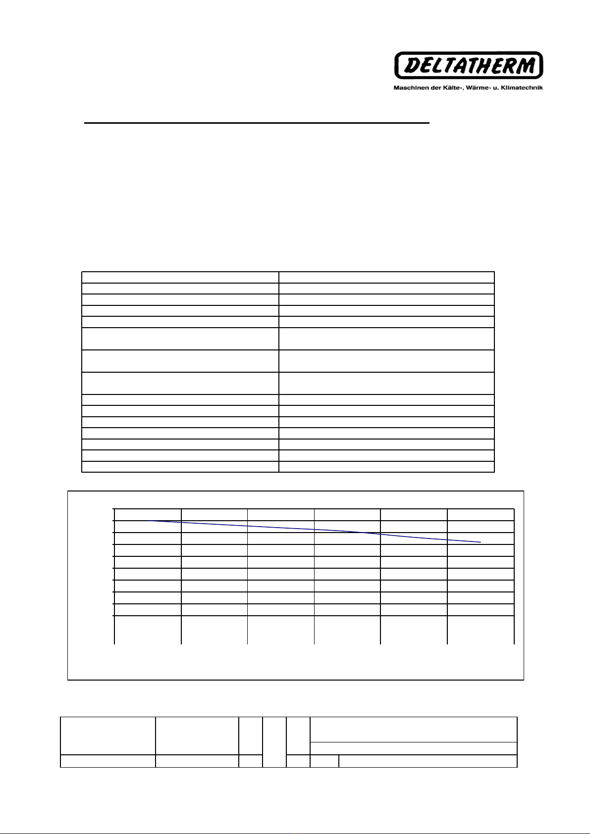
1. Technical data
Implementation Type
Cooling fluid
Cooling fluid filling quantity kg
Cooling performance at tw +20°C kW
Max. operating pressure bar
Min. water feed °C
Max. w ater feed °C
Min. environment temperature °C
Max. environment temperature °C
Compressor for tc/to=55/7°C
Amount Piece
Implementation
Nominal power kW
Nominal current A
Max. nominal current A
Evaporator
Implementation
Material
Condenser
Implementation
Material
V
entilator
Amount Piece
Implementation
Nominal power kW
Nominal current A
Air pow er m³/h
Nominal rotation speed n
Pump Amount Piece
Type
set transport power l/min
set transport pressure bar
Nominal power kW
Nominal current /max. A
Implementation
Implementation
Temperature display
Sw itching pow er AC / A
Container
Material
Contents Liter
Dim ensions
Width approx. mm
Depth approx. mm
Height approx. mm
Weight Weight approx. kg
Connection voltage
Control voltage
Nominal connection power kW
Nominal current draw A
Max. insulation A
28
1
completely sealed
2
,
86
3
,44
LT 5 VV PGD 50 Hz LT 5 VV PGD60 Hz
R 4
0
7
C
1
,
6
6
Axial ventilator w ith impeller
Temperature ranges ** +
10
+
2
5
+
10
+ 4
0
5,
1
air-cooled, axial
3
,
8
74,
02
Tube coils
C
u
C
u-tube
/
Alu-blades
S
4D4
00
AP
1203
1
0
,
13
5
0
,
18
5
1
45
0
1690
0
,44
0
,
39
22
5
0
Temperature regulator electronic
1
C
M
3
-
6
A-R-A-E-A
QQ
E
O
AAN
23
4
,7
47
0
0
,74
1
,
28
3
,
0
M
u
l
t
i
-stage
bl
oc
k
pump
Digital
2
PE
31
830
1200
19
5
Electrical connection
16
3
x 4
00
V 5
0/60
Hz +
6%/
-
10%
24V
DC
3
,74 4,
91
8
,54
8
,4
9
3
Operating manual for LT series cooling water heat exchanger
2. General safety information
Information marks in the operating manual
Safety information whose non-observance may cause danger to persons is
marked with the general danger symbol "Safety symbols according to DIN 4844-
W9".
When warning against electrical voltage, the marking occurs in accordance with
"Safety symbols according to DIN 4844-W 8".
General information that should be observed by the person performing the setup
or the operator is marked with the following symbol.
This operating manual does not contain any general safety rules for cooling and
electrical installations.
In accordance with EG machine directive 2006/42/EG from May 17th, 2006,
appendix II A, we declare that the designated machine complies with the basic
safety and health regulations of the EG directive 2004/42/EG from appendix I,
articles 1.1.2, 1.1.3, 1.1.5, 1.3.2, 1.5.1 in its design and construction. This
declaration becomes invalid in case of modifications without our prior
agreement.
Furthermore, compliance with the following regulations/directives applying to the
product is declared:
-EG Pressurized device directive (97/23/EG) from May 27th, 1997
-EMC Directive (2004/108/EG) from December 15th, 2004
-EG Low voltage directive (2006/95/EG) from December 12th, 2006
In particular the following harmonized standards:
-EN 60204-1:2006 Safety of machines; Electrical equipment of
machines; Part 1: General regulations
-EN ISO 12100:2003 Safety of machines; General requirements
-DIN EN 378-1 b. 4:1/2008 Cooling installations and heat pumps; Safety-relevant
and environmentally relevant requirements; Parts 1 to 4

4
Operating manual for LT series cooling water heat exchanger
Along with the general safety information listed in the following, you will find further
safety information in this operating manual under the main points as well as in the
section "In case of emergency". The directives and standards not named here also
retain their validity.
This operating manual contains basic information to be followed during setup, operation
and maintenance. Therefore, the operating manual is to be read by the assembler and
operator before the assembly and commissioning and should be constantly available on
the site of operation of the machine/installation.
Persons who are not familiar with this operating manual as well as children and
adolescents below age 16 may not use the device and should be kept away from the
connected device.
The working area is to be locked off in accordance with the task and should correspond
to the local directives on work protection.
Use personal safety equipment such as safety shoes, rubber gloves, protective goggles
and a helmet.
Ensure that all evacuation routes from the work area are unobstructed.
In order to prevent asphyxiation and poisoning, a sufficient oxygen supply to the
workplace is to be ensured and the absence of poisonous gases should be verified.
If work is to be performed with welding equipment or electrical tools, ensure that there
is no danger of explosion.
All safety and protective installations are to be mounted and started up immediately
after the end of works.
The operator is responsible for third parties in the working area.
We draw your attention to the fact that according to product liability regulations, we are
not responsible for damages caused by our device in the case where information and
directives from this operating manual are not respected. The same regulations apply for
accessories.
5
3. Description
The LT series air-cooled cooling water heat exchangers are compact devices and are
intended for cooling liquid fluids (Drinking water, all other fluids and additives are to
be released by the device manufacturer). The operating domain of the devices was
determined to be a fluid temperature between +10°C and +25°C. The stated cooling
performance relates to a fluid temperature of +20°C and an environment temperature of
+40°C (+50°C for tropical design). For physical reasons, the cooling performance
declines for sinking fluid temperatures and rising environment temperatures. In case of
rising fluid temperature and sinking environment temperature, the cooling performance
increases as defined by the laws of physics. A special equipment is necessary for the
use with demineralized water.
No flammable or explosive substances may be used.
In case of cooling fluid temperatures below +8°C, the cooling fluid should be
combined with adequate antifreeze in sufficient concentrations ( in accordance
with manufacturer information ).
Release for mixing ration water/antifrogen 70/30%.
Provided the cooling fluid is not mixed with antifreeze, the cooling fluid should be
completely drained in case of longer stoppage or during transportation with
environment temperatures below +4°C in order to avoid any frost damage.
4. Application domain
The cooling water heat exchangers are intended for cooling
- Molds and baths for the plastic industry
- hydraulic presses and dies
- Drilling and cutting emulsions
- Machine tools
- Welding machines, transformers and grippers
- Compressors and pipe coils
- Tri and Per cleaning installations
- Laboratory and experimental installations
- galvanic and chemical baths
- chemical and cosmetic emulsions
- Laser and X-ray installations
- Cooling walls and air-conditioning
- other systems
Operating manual for LT series cooling water heat exchanger
6
Operating manual for LT series cooling water heat exchanger
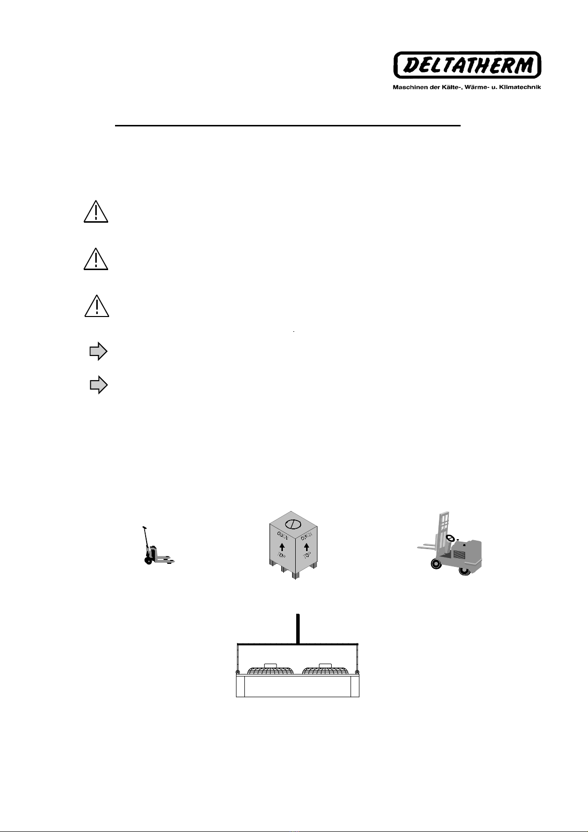
5. Transport
The heat exchanger may only be transported upright and with a completely empties
cooling fluid vat. The warning signs on the packaging should imperatively be observed.
Only use adequate transportation aids such as lifting equipment or forklifts during
transportation.
The delivery of the device is made with filled cooling fluid. When employing a
transporter, they should be informed of this. The type and quantity of cooling fluid are
provided in section 1.
The respectively applicable safety regulations are to be followed when transporting in
different countries or by boat or airplane. The safety data sheet for the used cooling
fluid may be obtained on demand from the manufacturer.
Before unpacking the heat exchanger, check the packaging or the device for any visible
transportation damage. In case of transportation damage, notify the transporter and the
manufacturer immediately.
If lifting brackets are available, always use all available lifting brackets during
transportation as non-compliance may cause damages to the housing and components.
When using lifting brackets, a lifting crossbeam should imperatively be used.
NO STEP

7
Operating manual for LT series cooling water heat exchanger
6. Function
The heat exchanger is mainly composed of a cooling circuit and a cold fluid circuit. The
cooling circuit serves the purpose of collecting the heat to be extracted from the user or
at the tool. The heat gathered by the cooling fluid is dissipated in the environing air via
thecoldfluidcircuit.
Cooling fluid circuit:
The cooling fluid transportation in the cooling circuit occurs via a built-in cooling
centrifugal pump and constantly circulates between the cooling fluid vat and the user.
The cooling fluid releases the heat to be evacuated via an evaporator in the cooling
fluid vat.
The cooling fluid vat is composed of high-resistance PE plastic as serves the purpose
of collecting the cooling fluid required for the cooling circuit. (See section "Technical
data" for contents of the container)
The filling level of the cooling fluid vat can be measured from outside using the
integrated filling level display.
Cooling fluid pump:
A robust, multi-stage block pump is used for the recirculation of the cooling fluid
required for cooling.
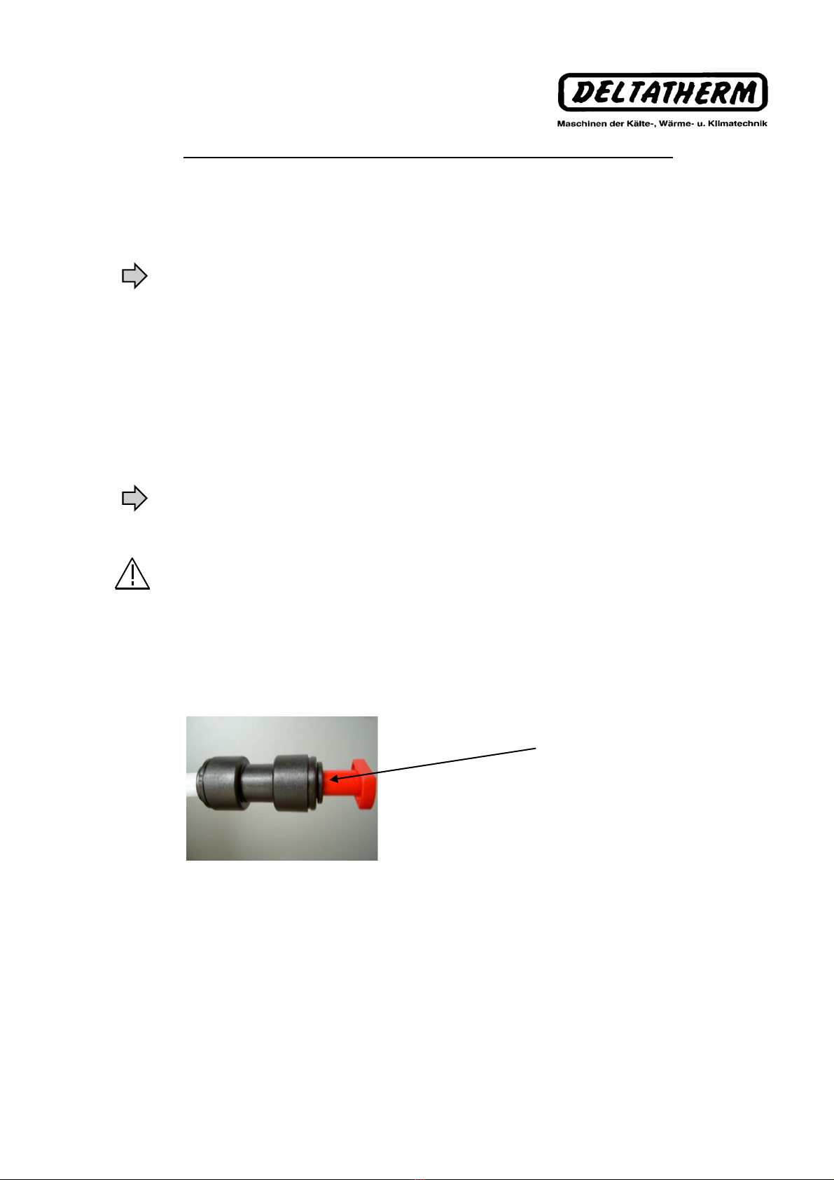
The pump must be deaerated at the pump head before commissioning. A deaeration
tube which is closed with a red lid is attached to the pump head for this purpose. The lid
is to be removed before filling. Filling is done via the filling nozzle on the casing lid. If
the water level reaches the upper mark on the water level display, filling of the device is
complete.
Avoid dry running of the pump
Cold fluid circuit:
The cold fluid circuit functions with safety cooling fluid R407C (R134a for tropical
design). This cold fluid is not poisonous, non-flammable and non-explosive.
The cold fluid is propelled by the compressor and circulates in a closed circuit between
the evaporator and condenser. If collects the heat from the liquid to be cooled in the
evaporator and thereby changes its state from liquid to gaseous. The gaseous
overheated cold fluid is sucked up by the compressor and compressed. The
compression of the cold fluid increases the pressure and temperature in the cold circuit.
The collected heat including the compression heat is dissipated in the environing air in
the condenser, and the cold fluid condenses at constant pressure. The condensing
pressure is brutally dropped at the thermostatic expansion valve mounted between
condenser and evaporator, allowing liquid cold fluid to be injected to the evaporator.
The injecting cold fluid evaporates again in the evaporator by obtaining the necessary
evaporation energy through heat collected from the cooling fluid. This circular process
repeats as long as the compressor is switched on, or as long as the desired target
temperature set on the temperature controller is not reached.
8
Operating manual for LT series cooling water heat exchanger
Evaporator:
The evaporator is designed as a pipe coil heat exchanger and is located in the
cooling fluid vat. The used material is exclusively copper. The cooling fluid runs
through the heat exchanger tubes during the heat exchange and the fluid to be
cooled flows around the tubes. The evaporator pipe coils should always be
surrounded by sufficient fluid to be cooling fluid, as the cooling performance
diminished otherwise.
Condenser:
An air-cooled blade condenser is used for heat evacuation. The condenser retrieves
approx. 1,3 times the heat quantity of the cooling performance.
Collector:
The collector is used to collect the cooling fluid necessary for the sage operation of
the unit.
Inspection glass:
The inspection glass is used to check the cold circuit in case of faults.
Permanent bubbling in the inspection glass during operation indicates a lack of
cooling fluid.
High pressure control:
The high pressure control acts as a safety organ in the cold circuit and switches off
the compressor in case of excessive pressure in the system.
Low pressure control:
The low pressure control acts as a safety organ and switches off the compressor in
case of too low pressure in the system.
Floater switch for too low water level
The pre-warning "Water level too low" indicates that too little water is present in the
container. The missing water should be filled in.
Protection against dry running
The protection against dry running serves the purpose of protection the recirculation
pump and the compressor from damage. If the min. water level is reached, it
switches off the device. The device only switches back on once the min. filling level is
exceeded.
No further description of the cold circuit will be given here, since further manipulation
of the circuit should only be performed by trained cooling technicians.

9
Operating manual for LT series cooling water heat exchanger
7. Setup
The corresponding local regulations should be observed when setting up the heat
exchanger.
In accordance with accident prevention directive BGR500, it should be ensured that the
place of setup has a large enough ventilation area and is sufficiently ventilated in the
case of a cooling fluid leak.
The setup of the heat exchanger should preferably be performed in a frost-safe room.
The minimum distances provided in the dimensions sheet should be respected. It
should be ensured that the room air does not become excessively warm because of the
heat to be evacuated. If heating of the room is unavoidable due to the available room
dimensions, the generated heat should be evacuated using adequate additional
installations (for examples windows or ventilators) and cooler air should be transported
into the room. High room temperatures lead to high pressure switch-offs in the cooling
circuit and thereby reduce the cooling performance of the device. The air in- and outlet
grills should not be blocked.
In order to prevent unnecessary pressure losses in the pipes connecting to the user, the
heat exchanger should be set up as close as possible to the tool to be cooled. The
connection tubes are to be insulated against unnecessary heat uptake and
condensation water formation using adequate insulation materials (for example
Armaflex).
A special base is not necessary for the setup of the heat exchanger, a level installation
on a floor capable of supporting its mass is sufficient.
10
8. Cooling circuit connection
The heat exchanger is a compact device and contains all the parts necessary for cooling the
fluid. Only the connection tubes between the heat exchanger and the user to be cooled or the
tool are to be provided on-site. The fluid in- and outlets are to be connected using flexible
pressure tubes. No rigid pipe connections are to be created. The flow direction is marked by
arrows on the connections.
The filling of the container is done via a filling connection on the device lid.
When filling the device, observe the following:
a) Before the feed and reflux pipes are connected, the container in the device is to be pre-filled
to the
maximum filling level (see upper marking on the filling level display). The
air contained in the system can thereby escape in an optimal fashion.
b) During first filling, the pump and pump head are to be deaerated. For this,
a deaeration tube is attached to the top of the pump head and is closed off by a red
plug. The lid is to be removed before filling. Filling is done via
the filling nozzle on the casing lid. If the water level reaches the upper mark
on the water level display, filling of the device is complete. The de-
aeration tube is to be closed with the red plug.
Avoid dry running of the pump
c) At the end of the filling process, the device is to be connected to the feed and
reflux tubes as described above.
In order to pull out the plug
press the side ring of the
plug connection towards the back.
Operating manual for LT series cooling water heat exchanger

11
Operating manual for LT series cooling water heat exchanger
If the user is mounted higher than the heat exchanger, the container may overflow due
to water reflux once the recirculation pump is switched off. In this case, a holding valve
should be installed in the feed and a magnetic valve in the reflux tube.
3
6
1
9
2
338
47
7
B
12
A
5
3
6
65
4
6
3
2
Verbraucher
Rückschlagventil
Magnetventil
Absperrventil
Füllanschluß
Absperrschieber für Druck- u
n
Durchflußmengen Einstellung
8
9
Entlüfter
4
5
6
7
3
Absperrventil
Verbraucher
Füllanschluß
Absperrschieber für Druck- u
n
Durchflußmengen Einstellung
4
Pumpe
Behälter1
Entlüfter6
5
7
Behälter
Pumpe
1
2
3
1 Container
2Pump
2 Shut-off valve
3 Shut-off slider for setting the
pressure and flow rate
5User
6 Deaerator
7 Filling connection
1 Container
2Pump
2 Shut-off valve
3 Shut-off slider for setting the
pressure and flow rate
5User
6 Deaerator
7 Magnetic valve
8 Holding valve
9 Filling connection
12
Operating manual for LT series cooling water heat exchanger
9. Electrical connection
The electrical connection of the device should be performed in accordance with VDE
0/100 and the TAB of the responsible EVU.
The expert verification before commissioning should determine that the required
protective measures are available.
The power connection is done using a Harting plug.
If the device is connected to a three-phase mains, the rotating field and the rotation
direction of the pump and ventilator motors should be checked. If necessary, the
rotation direction should be corrected by exchanging two outside wires.
The device connection should occur with a right hand rotation field.
ONLY FOR SPECIAL VOLTAGES
If a power transformer is built into the device, the mains connection is directly made on
the connections of the transformer. The protective sheet over the terminal block has to
be removed first.
MAINS VOLTAGE see identification plate
13
Operating manual for LT series heat exchanger
10. Commissioning
If the cooling circuit is filled as described in point 8 and the device is electrically
connected as described in point 9, the heat exchanger may be started / stopped
using the button, see controller description in the appendix.
The error notifications are to be requested as aggregate error notifications with
potential free queries to the Harting connector. See circuit diagram.
In case of deviations of the set value, a warning signal is output to the display of
the controller.
Information on hydraulic device adaptation
A hydraulic adaptation to the local conditions is to be performed on-site for each
device. For this, DMG co. need to install baffle plates in order to regulate the
corresponding flow rates. It should be ensured that the set water pressure and the
flow rates are in the application domain of the pump characteristic. Operating
conditions deviating from this may cause damages to the pump.
14
Operating manual for LT series cooling water heat exchanger
11. Care and maintenance
The heat exchanger requires no special care as the device is constructed in a manner
that ensures maximum operating safety and the lowest possible requirements towards
maintenance, inspection and monitoring.
However, in order to avoid faults and damages, it is necessary to observe the following
points.
1.) The condenser blades and protective grills must be free of dust and dirt. If
necessary, these are to be cleaned using compressed air.
2.) The pipe coil evaporator should be cleaned in accordance with the state of the fluid.
Dirty fluid should thereby be drained.
3.) The air filter mat should be regularly changed.
If pollution occurs after a short time when using water as cooling fluid, the cooling water
should be prepared (see water preparation).
12. Repair
The following paragraphs should imperatively be observed when repairs are to be
performed.
Only remove the metal cover sheets with the device turned off.
All maintenance and repair work should be performed with the device disconnected
from all power sources.
Work on the electrical installation may only be performed by expert electricians.
The applicable VDE directives and annex regulations of the responsible EVU are to be
observed.
Safety installations should never be bridged.
Work on the cold circuit may only be performed by trained cooling technicians. For
environmental protection reasons, the cooling fluid may not be released into the
atmosphere. The cooling fluid should be suctioned off and disposed of in the adequate
manner.
In case of a defect on the machine within the warranty period, all repairs may only be
performed by the manufacturer or an authorized expert workshop.
Modifications to the device are only admissible with prior consent of the manufacturer.
Only original spare parts should be used.
We draw your attention to the fact that according to product liability regulations, we are
not responsible for damages caused by our device in the case where unauthorized
repair attempts are performed neither by the manufacturer or by an authorized
workshop, or when parts are exchanged for non-original replacement parts.
The same regulations apply for accessories.

15
13. Faults and causes
Work on the cooling circuit and work on the electrical wiring may only be performed by
trained expert personnel or the DELTATHERM service.
Verifications and repairs may only be performed if the device is disconnected from all
power supplies.
Fault Cause Solution
Operating manual for LT series cooling water heat exchanger
Too low cooling
performance Condenser or evaporator are
polluted
Lack of cooling fluid
Environment temperature too
high
Device is overloaded
Filter mat is blocked
Clean parts
Have an expert remedy
the leak
Fill in cooling fluid
Reduce room
temperature through
adequate measures (i.e.
additional ventilators)
Check whether additional
users were connected or
the production conditions
changed
Change the filter mat
Pump runs, compressor
does not switch on
“Fault” Temperature
regulator temperature
excess
“Fault” Pump does not
switch on
“Fault” Motor protection
switch “Compressor”
“Fault” High pressure
switch
“Fault” low pressure
switch
Filling level fault
Check settings on
temperature control
Fluid temperature is too
high
Motor winding protection
in motor winding is open
If necessary, exchange
temperature control
Have expert check
Limit values are
exceeded or underrun Check temperature
control and device
Check sensor
“Pump” motor protection
switch triggers Check fuses
Pump works outside its
characteristic
“Compressor” motor
protection switch triggers
Compressor does not
switch on
Check fuses
Environment temperature
too high
Condenser polluted
Ventilator defective
Have expert check
Fluid temperature too low
Condenser polluted
Lack of cooling fluid
Cold circuit component defective
Raise temperature
Clean condenser
Have expert check
Filling level in the container too low
Leak in the fluid circuit Check filling level
Refill fluid
Look for leak

16
Pump characteristic at 50Hz
Operating manual for LT series cooling water heat exchanger
Implementation
Horizontal, multi-stage high pressure centrifugal pump in block design
Application domain
For pure, non-explosive transport liquids without abrasive or solid components,
without suspensions, and that do not corrode the pump materials.
For increasing the pressure of the water network (observe local regulations).
Operating conditions
Ty
pe
CM
3
-
6
A
-
R
-
A
-
E
AQQE
O
-
A
-
A
-
N
Fl
u
id
t
empera
t
ure -
20
- +
120
E
nv
i
ronmen
t
t
empera
t
ure max.
55
°C
M
ax
i
mum a
d
m
i
ss
ibl
e pump pressure
10
b
a
r
C
ons
t
an
t
opera
ti
on
Y
es
P
ump
h
ous
i
ng
/
V
a
l
ve yo
k
e
G
ray
i
ron
EN
-
JL1030
AISI
30
B
I
mpe
ll
er
St
a
i
n
l
ess s
t
ee
l
DIN
W
.-
N
r.
1
.
4301
,
AISI
304
A
x
i
s
St
a
i
n
l
ess s
t
ee
l
1
.
4301
(AISI
304)
A
x
i
s sea
l
AQQE
M
o
t
or
2
po
l
.
i
n
d
uc
ti
on mo
t
o
r
F
requency
50/60
H
z
C
onnec
ti
on vo
lt
age
3
~
400V
I
nsu
l
a
ti
on c
l
ass
F
P
ro
t
ec
ti
on
t
ype
IP
55
Characteristic data n = 2900 1/min
Type 3~ 400V 50 Hz P2 HP Q
m³/h 0,8 1,2 1,6 2,0 2,4 2,8
AkWHP
l/min 13,28 19,92 26,56 33,2 39,84 46,48
CM 3-6 IE2 0,74 56 54 52 50 47 43
3,00
0
10
20
30
40
50
60
13,28 19,92 26,56 33,2 39,84 46,48
0,8 1,2 1,6 2,0 2,4 2,8
H
m
Q
l/min
m³/h
17
Pump characteristic at 60Hz
Operating manual for LT series cooling water heat exchanger
Implementation
Horizontal, multi-stage high pressure centrifugal pump in block design
Application domain
For pure, non-explosive transport liquids without abrasive or solid components,
without suspensions, and that do not corrode the pump materials.
For increasing the pressure of the water network (observe local regulations).
Operatin
g
conditions
T
y
pe CM 3-6 A-R-A-E AQQE O-A-A-N
Fluid temperature -20 - +120
Environment temperature max. 55 °C
Maximum admissible pump pressure 10 ba
r
Constant operation Yes
Pump housing / Valve yoke Gray iron
EN-JL1030 AISI 30 B
Impeller Stainless steel
DIN W.-Nr. 1.4301 AISI 304
Axis Stainless steel
DIN W.-Nr. 1.4301 AISI 304
Sliding ring seal
A
QQE
Motor 2 pol. induction motor
Frequency 50/60 Hz
Connection voltage 3~400V
Insulation class F
Protection type IP 55
Design according to
Characteristic data
n =
3480
1/min
Type 3~ 400V 60 Hz P2 HP Q
m³/h 1,0 1,5 2,0 2,5 3,0 3,5
AkWHP
l/min 16,6 25 33,3 41,6 50 58,3
CM 3-6 IE2 1,28 80 77 74 71 66 62
3,0
0
10
20
30
40
50
60
70
80
90
16,6 25 33,3 41,6 50 58,3
1,0 1,5 2,0 2,5 3,0 3,5
H
m
Q
l/min
m³/h
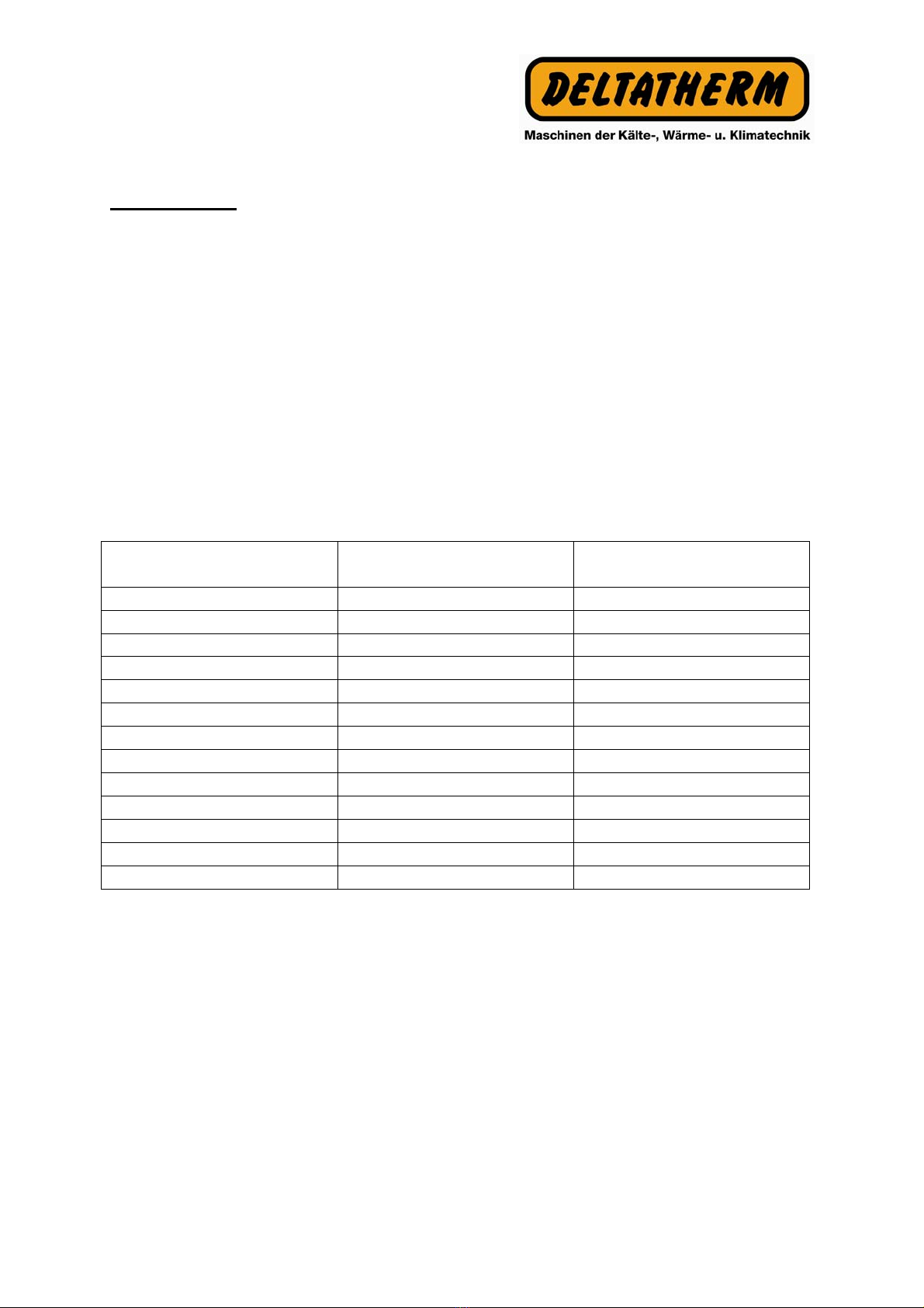
Water quality
Requirements and water-care for heat-exchangers (chillers) and heat-balancing plant
(temperature control units)
Subject to the equipment to be cooled or heat-balanced, certain requirements have
to be met by the cooling water regarding cleanliness and purity. The degree of the
water`s contamination, as well as the size and construction of the heat-exchanging-
or –balancing plant determine the process most suitable for the application of
additives and/or care of the water-supply in question.
In the interest of achieving the optimum layout for operating an appropriate heat-
exchanger unit or heating-cooling plant, the consistency of the water used schould
not deviate too significantly from the following list of hydrological data:
Hydrological Data max. unit
PH-value 7,5 – 8,5 -
Carbonate hardness 3 - 5 °dH
Free carbonic acid 0 mg/l
Carbonic acid 0 mg/l
Aggesiv carbonic acid 0 mg/l
Chlorid Cl <50 mg/l
Sulphate So4 10 mg/l
Nitrate and nitrite <50 mg/l
Ammonia 0 mg/l
Iron Fe 0,1 mg/l
Manganese 0,05 mg/l
Free from solids 0 mg/l
Conductivity 600-1000 µS/cm
With deviating water-quality, we recommend using the services of consultants, or to
have a water analysis or water sample sent to us.
Deltatherm is not liable for any malfunctions or damages arising from deviating water
qualities.
When employing chillers at temperatures below + 8°C, an anti-freeze medium must
be added (Release by DELTATHERM).
This manual suits for next models
2
Table of contents


