Neptronic WP Series Manual

WP Series - 2521 System Manual- 220407.docx
Reverse Osmosis Systems
WP Series
WP25211, WP25212, WP25213 Models
Installation Instructions and User Manual
READ AND SAVE THESE INSTRUCTIONS

WP-Series Reverse Osmosis System
Installation Instructions and User Manual
www.neptronic.com
Page | - 2 -
Foreword
Neptronic Company Overview
Founded in 1976, we’re a private corporation that designs, manufactures and distributes products for the HVAC industry.
Our product line includes intelligent controllers, electronic actuators, actuated valves, humidifiers and electric heaters.
Our products are designed and manufactured by over 250 dedicated employees in our 7,500 m2 (80,000 ft2) state-of-the-
art facility located in Montreal, Canada. Using a vertical integration model, our entire manufacturing chain is under one roof,
from software and hardware development to SMT circuit board assembly, to sheet metal fabrication, to product testing,
ensuring that our products are engineered to last.
We currently hold several national and international patents and with our continued commitment to research and
development, we provide innovative products and technologies for the ever-evolving challenges of the HVAC industry.
Exporting over 70% of our sales, we have an exclusive distribution network around the globe that provides comprehensive
solutions to our worldwide customers.
About the Manual
These installation and operation instructions have been developed to facilitate the installation of the Reverse Osmosis for
the WP-Series humidifiers.
•The strict application of these instructions will ensure the conformity of your installation and operation as per
the manufacturer's recommendations.
•The application of these instructions is one of the conditions for the application of the warranty.
•The application of these instructions does not ensure, at any time conformity to procedures, regulation or local
codes, regarding electric installation and connection to local water supply.
This product has been declared to conform to the applicable Canadian and American safety standards and directives and
bear the ETL (c) & (us) mark. The Certificate for ETL is available, upon request to the manufacturer.
2022©: All rights reserved. This document cannot be reproduced totally or partially by any means whether, electronic,
mechanical, photocopy, recording or other, without prior written authorization of Neptronic.
Electricity
All work concerned with electrical installation MUST only be performed by skilled and qualified
technical personnel, such as an electrician or a technician with appropriate training. The customer is
always responsible for ensuring the suitability of the technical personnel.
Please observe the local regulations concerning the provision of electrical installations.
Correct Use
Neptronic systems and its products are designed only for humidification use. Any other application is not considered
appropriate for the intended purpose. The manufacturer cannot be made liable for any damage resulting from incorrect use.
General Warranty
This product is subject to the terms and conditions described at http://www.neptronic.com/Sales-Conditions.aspx.

WP-Series Reverse Osmosis System
Installation Instructions and User Manual
www.neptronic.com
Page | - 3 -
Contents
General Information and Safety .............................................................................................................................................. 5
RO System Specifications....................................................................................................................................................... 6
Operational Notes................................................................................................................................................................ 6
WP Series Specification Sheet............................................................................................................................................ 7
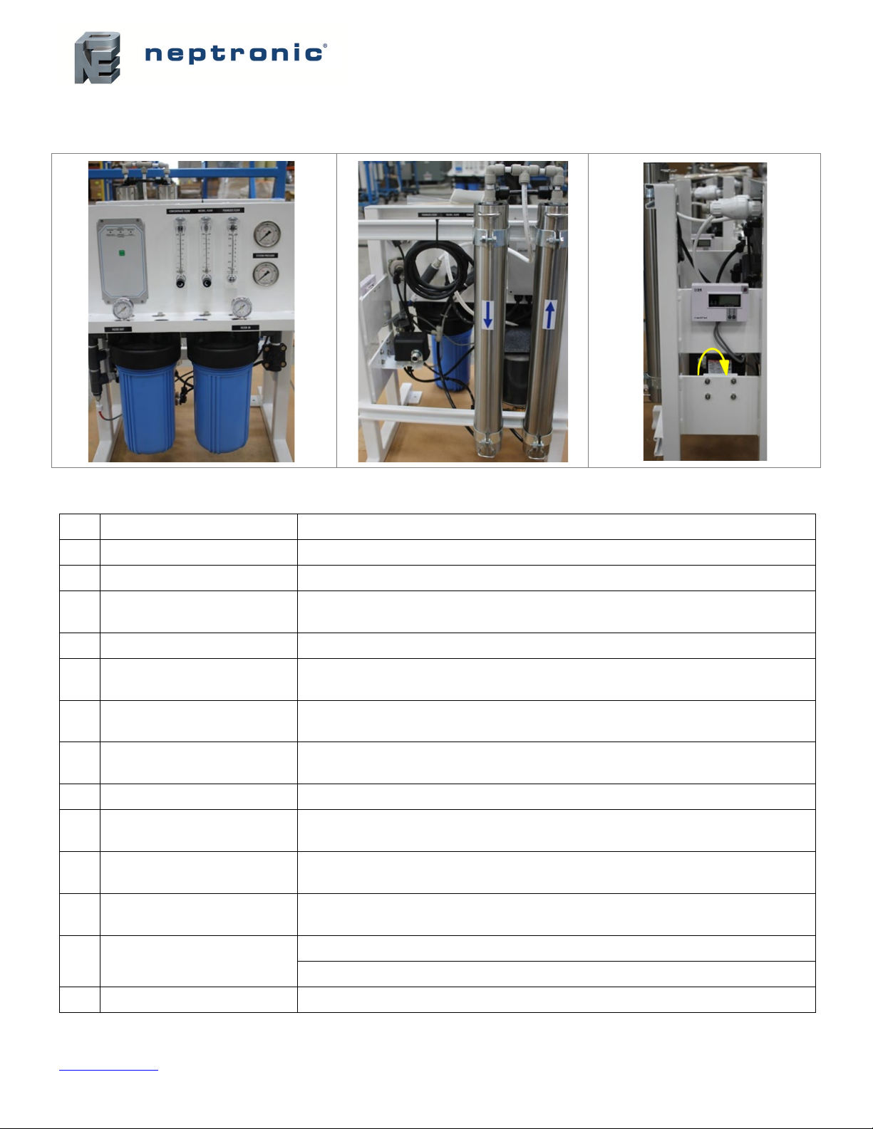
Component Identification..................................................................................................................................................... 9
System Installation ................................................................................................................................................................ 10
Location ............................................................................................................................................................................. 10
Series 50 Controller .............................................................................................................................................................. 12
Specifications .................................................................................................................................................................... 12
RO Pump Wiring ............................................................................................................................................................ 15
Inlet Wiring ..................................................................................................................................................................... 15
Pressure Fault Switch .................................................................................................................................................... 15
Pretreat Switch............................................................................................................................................................... 15
Tank Full Switch............................................................................................................................................................. 15
System Operation ................................................................................................................................................................. 16
Series S50 RO System Controller Operation .................................................................................................................... 16
General Operation ......................................................................................................................................................... 16
Initial System Start-Up....................................................................................................................................................... 17
System Flush ................................................................................................................................................................. 17
Normal Operations ............................................................................................................................................................ 17
Shutdown........................................................................................................................................................................... 18
Maintenance Tips.................................................................................................................................................................. 19
When To Change Cartridge Pre-Filters............................................................................................................................. 19
When To Clean Membranes.............................................................................................................................................. 19
Membrane Cleaning and Preservative Cartridges:........................................................................................................ 19
Membrane Cleaning in RO System: .............................................................................................................................. 19
How do they Work?........................................................................................................................................................ 19
Acidic Cleaning Cartridge .................................................................................................................................................. 20
Cleaning Procedure ....................................................................................................................................................... 20
Alkaline Cleaning Cartridge............................................................................................................................................... 20
Cleaning Procedure ....................................................................................................................................................... 20
Storage Protection............................................................................................................................................................. 21
C-C4210-A88 Membrane Preservative Cartridge.......................................................................................................... 21
Flushing out Preservative/Re-start Procedure:.............................................................................................................. 21
Replacing Membranes .......................................................................................................................................................... 22
Procedure .......................................................................................................................................................................... 22
Replacing Prefilters ............................................................................................................................................................... 23

WP-Series Reverse Osmosis System
Installation Instructions and User Manual
www.neptronic.com
Page | - 4 -
Procedure .......................................................................................................................................................................... 23
Adjustment Of Pressure Switch ............................................................................................................................................ 24
Temperature Correction Factor............................................................................................................................................. 25
Operating Do's and Don’ts .................................................................................................................................................... 26
System Monitoring and Record Keeping .............................................................................................................................. 27
General Troubleshooting....................................................................................................................................................... 28
Component Part Numbers .................................................................................................................................................... 29

WP-Series Reverse Osmosis System
Installation Instructions and User Manual
www.neptronic.com
Page | - 5 -
General Information and Safety
Disclaimer: The information contained in this document is subject to change without notice. Applied Membranes, Inc.
shall not be liable for technical or editorial omissions made herein; nor for incidental or consequential damages resulting
from the furnishing, performance, or use of this material.
Power Connections: Use proper wiring and connection methods to satisfy local electrical codes.
•Connect this unit to a properly grounded connection in accordance with the National Electrical Code.
•Do not, under any circumstances, remove the ground wire or ground prong from any power plug.
•Do not the use extension cord or an adapter without proper consideration.
WARNING: Risk of electric shock. Disconnect the appliance from electric supply before
commencing servicing.
WARNING: Do not make any alteration or modification in the wiring or plumbing of the system.
This can result in damage to the system and cause injury to operators or users.
WARNING: Flush the system for at least 30 minutes before use to remove all chemicals present.
CAUTION: Chlorine will damage the membranes. A carbon pre-filter is installed to remove
chlorine from feed water. Care must be taken to change this carbon filter as needed to
accomplish effective chlorine removal. Excessive chlorine in feed stream may require additional
pre-filtration. The feed stream should be tested for chlorine at least once a week. Always follow
proper maintenance
CAUTION: Never let the system freeze. Freezing can damage the membrane and plumbing.

WP-Series Reverse Osmosis System
Installation Instructions and User Manual
www.neptronic.com
Page | - 6 -
RO System Specifications
Table 1 - RO System Electrical Specifications
Model Hz Motor HP Volts Phase
WP25211-116 60 1/3 115/230 1
WP25211-215 50 1/3 220/230 1
WP25211-216 60 1/3 220/230 1
WP25212-116 60 1/3 115/230 1
WP25212-215 50 1/3 220/230 1
WP25212-216 60 1/3 220/230 1
WP25213-116 60 1/3 115/230 1
WP25213-215 50 1/3 220/230 1
WP25213-216 60 1/3 220/230 1
Operational Notes
1. All systems rated at 77 Degrees Fahrenheit (25 Degrees Celsius) using 1000 ppm sodium chloride (NaCl)
solution. System capacity decreases significantly with decrease in feed water temperature (see temperature
correction chart).
2. Chlorine requirements for the feed water are as follows:
Thin-Film (standard) 0 ppm
CA (special order only) 0.1 ppm Minimum
3. Feed water must be filtered to a turbidity of less than 1 NTU.
4. System recovery (permeate to concentrate ratio) must be maintained at the recommended level. A higher than
recommended recovery will lead to a premature fouling of the membrane with a loss of permeate flow and permeate
quality.
5. Softened water should be used for the feed water to the RO system.

WP-Series Reverse Osmosis System
Installation Instructions and User Manual
www.neptronic.com
Page | - 7 -
WP Series Specification Sheet
Table 2 - WP Series Specification Sheet
MODEL WP25211 WP25212 WP25213
Rated Capacity, Permeate*
- Gal/Day 350 700 1000
- Gals/Min .24 .48 .70
- Cubic Meters/Day 1.3 2.7 3.8
Concentrate Flow (Reject)
- Gals/Min 1.1 1.2 .97
- System Pressure, PSI 100-150 100-150 100-150
- Degrees Celsius/ Degrees F 25/77 25/77 25/77
Pre-Filters
- Sediment Cartridge - 5 micron 1 1 1
- Carbon Cartridge - 10 micron 1 1 1
Pressure Switch Settings
- Low Pressure (for pump protection) 8 PSI 8 PSI 8 PSI

WP-Series Reverse Osmosis System
Installation Instructions and User Manual
www.neptronic.com
Page | - 9 -
Component Identification
1
33
10 11
9
12a 54
2
12
12b
8 8
7
6
13
12
6
Illustration 2 – System Components
Table 3 - Component Description
# Item Description
1. Controller Power On/Off and Status Display
2. Inlet Solenoid Valve Normally closed. Opens when power is applied.
3. Cartridge Filter Pressure
Gauges (In-right/Out-left)
Measure the feed and effluent pressure of the cartridge filters. Pressure
difference determines when cartridge change-out is required.
4. Sediment Filter 5-micron sediment filter.
5. Carbon Filter 10-micron extruded carbon cartridge to remove chlorine and reduce organics
from the feed stream.
6. Low Pressure Switch Shuts the system down if the inlet pressure is lower than 8 psi (adjustable).
7. High Pressure Pump &
Motor Rotary pump and motor to pressurize the incoming water.
8. Membrane Modules RO Membrane elements housed in stainless steel pressure tubes.
9. System Pressure Gauges Measure the System (feed) and Concentrate (effluent) pressure of the
membrane modules.
10. Concentrate Control Valve To adjust system pressure. Must not be completely closed when the system is
in operation.
11. Recycle Valve To adjust and maintain adequate flow thru membranes.
12. TDS Monitor Monitors the feed and permeate water quality.
12a – feed sensor; 12b – permeate sensor
13. Permeate Check Valve Prevents backflow into RO module.

WP-Series Reverse Osmosis System
Installation Instructions and User Manual
www.neptronic.com
Page | - 10 -
System Installation
Location
Locate R.O. system with adequate clearance from walls and other equipment to enable membrane servicing. Run three
polyvinyl tube lines to the system as follows:
•Line #1: Connect raw water feed supply to the solenoid valve inlet in front of the first cartridge filter housing. This
will require ½ inch threaded pipe fitting and adaptor for the feed line. If desired, install an isolation valve in this
line; ensure the valve opening does not restrict the water flow.
Illustration 3 - Line 1 Connection
CAUTION:
Pump and system performance will be adversely affected if the feed/suction line is
restricted.
•Line #2: Run a 3/8" line from the open end of the concentrate valve to a drain. Ensure that no liquids from other
lines in the plant flow back through this line.
Illustration 4 - Line 2 & 3 Connections
•Line #3: Run a 3/8" line from the permeate outlet to desired permeate storage container. Pressurized storage or
atmospheric storage tank options are available separately.
Note: The recirc flow line is pre-connected at the factory.
CAUTION: Be sure that all lines are connected before plugging in unit power.

WP-Series Reverse Osmosis System
Installation Instructions and User Manual
www.neptronic.com
Page | - 11 -
Connection of Multi-Media, Carbon or Softeners to Lock-Out (Shut-down) RO during back-wash or regeneration:
If you have pre-treatment equipment and you wish to shut-down the RO system during backwash or regeneration, a
microswitch is required (standard with Applied Membranes equipment). Wire the microswitch to terminal labeled Pretreat
inside controller. See photo - Page 12.
When equipment goes into backwash or regeneration, the pre-treat limit switch opens and turns power off the inlet
solenoid valve, which then turns the RO pump off - and back on when the cycle is complete.

WP-Series Reverse Osmosis System
Installation Instructions and User Manual
www.neptronic.com
Page | - 12 -
Series 50 Controller
Specifications
Power: 120VAC - 240VAC, 50/60 Hz, +10/-15%, 2.5 watts. Input power is auto selected
Inputs: 3 switch inputs, selectable normally open or normally closed
Outputs: RO pump 1HP (Based on service factor of 1.0 max), Inlet solenoid 5A, 20A maximum total load
If you desire to change any switch functions, move that switch to the ON Position.
Note: The switches are factory set to the OFF Position: Auto Reset (disabled), Pressure Fault Retry
(disabled), Tank Full restart time delay (2 seconds), Input contact type (NC, open to operate).
Illustration 5 – DIP Switches
CAUTION:
The controller is rated for maximum 20A total load. Terminal strip P11 is dry contact for input
signals from tank full, pressure fault and pre-treat lockout. Use small gauge 2 conductor cable for these
wire connections.

WP-Series Reverse Osmosis System
Installation Instructions and User Manual
www.neptronic.com
Page | - 15 -
The RO pump connects to P4 (L1) and P5 (L2) RO pump terminals. This output can operate 120/240VAC motors up to
1HP directly.
The inlet solenoid valve connects to P6 (L1) and P7 (L2) inlet terminals.
The feed pressure switch is connected to the pressure fault input. Low pressure (factory preset 8 psi) will shut system off.
In systems with pretreatment, a pretreat lockout switch can be connected to the pretreat input. This switch should operate
when the pretreatment device is out of service.
Note: The output from the pre-treatment device must be a dry contact and must not supply voltage.
In systems with a level or pressure switch, the switch can be connected to the tank full input.
RO Pump Wiring
Inlet Wiring
Pressure Fault Switch
Pretreat Switch
Tank Full Switch

WP-Series Reverse Osmosis System
Installation Instructions and User Manual
www.neptronic.com
Page | - 16 -
System Operation
Series S50 RO System Controller Operation
The unit has a single mode of operation ON with 6 sub-modes or states as indicated by the steady or flashing panel lights.
Any light condition other than steady Power ON indicates the unit is effectively in stand-by. If there are no lights – system
is OFF and all outputs are turned off. In the operating mode, the unit operates automatically. All inputs are monitored, and
the outputs are controlled accordingly. Pressing the Power key will toggle the unit from off to operate or from operate to
off. If power is removed from the unit, when power is reapplied, the unit will restart in the mode it was in when power was
removed.
Illustration 8 - Controller Sub-Modes
Power Key: Places the controller in operating mode.
Pressure Retry: Steady red light.
Pressure fault: Flashing red light.
Power On: Steady green light. System operating.
Pretreat: Flashing green light.
Tank Full: Steady amber light.
Flush: There is no Flush sequence.
When the power switch is turned ON, the center status LED will light Green, the inlet valve will OPEN and the RO pump
will START. (Refer also to Switch - pages 12.)
Under normal operation the RO unit will run until: (A) the storage tank is full (right LED Amber) or (B) Pretreat lockout has
occurred (center status LED Flashing Green). When A or B has cleared, after a time delay, the RO unit will restart, and
the center status LED will return to Green. Switch setting 3 selects a 2 second- or 15-minute tank full restart time delay.
Upon an alarm signal for Pressure Fault, the left status LED will Flash Red, the RO pump will stop and the inlet valve will
close and the RO pump will turn OFF.
If switch 1 and 2 are in the OFF Position (disabled), the left status LED will be a steady RED and the RO will not restart
until the Power Switch has been manually cycled OFF then ON to reset the unit. If switch 1 is in the ON Position (auto
reset), every 60 minutes the RO will start and stop again if a pressure fault continues.
If switch 2 is in the ON Position (pressure fault retry), the RO will attempt to restart after 30 seconds, then 5 minutes, then
30 minutes. If the pressure alarm has not cleared after the third try, the RO unit will remain off until manually reset.
If switch 1 and 2 are in the ON Position, after a pressure fault condition, the RO unit will continually attempt to restart after
each 60-minute cycle, until the pressure switch input has cleared.
General Operation

WP-Series Reverse Osmosis System
Installation Instructions and User Manual
www.neptronic.com
Page | - 17 -
Initial System Start-Up
Note: Direct permeate flow to drain for first 30 minutes of operation.
1. Connect the system to the appropriate electrical outlet, 110vac or 220vac 1 phase.
Note: Follow all NEC and local electrical codes.
2. Ensure all plumbing connections are open to allow flow. Open Concentrate Valve (counterclockwise). Close
Recirc Valve (clockwise).
Illustration 9 – Concentrate & Recirc Valve
Ensure sufficient pressure (40 psi recommended) is in feed line. If pressure is less than 8 psi, the low-pressure
switch will disallow start-up until pressure is adequate.
3. Press the Power button; the solenoid will open and the unit will start operating.
4. After water is flowing from the concentrate line, adjust the control valve to obtain designated flow for the specific
model. (See Specifications Table – Page 6.)
5. Allow the unit to run for 30 minutes to ensure proper flushing of system.
6. After the flush time is over, press the Power button off.
7. Redirect the permeate line to the desired location.
Normal Operations
1. Turn the power back on. After the pump starts, adjust the control valve to the desired flow / pressure (not to
exceed 150 psi).
2. The recycle valve may now be adjusted to achieve desired recycle flow rate, ensuring concentrate flow rate is as
specified (Page 6).
CAUTION:
To prevent concentrate from precipitating and causing irreversible fouling of the RO
membrane, do not operate the system with the control valve CV2 completely closed. Also, do not
exceed recommended maximum recovery.
System Flush

WP-Series Reverse Osmosis System
Installation Instructions and User Manual
www.neptronic.com
Page | - 18 -
Shutdown
1. Press power button to shut unit off. Close isolation valve, if installed on feed line.
2. If the unit is to be shut down for more than 1 week, a membrane preservative should be used. To accomplish
this, perform 30 second flush using cartridge filter insert AMI No. C-C4210-A88. After 30 seconds, press Power
button (Off) and close "Concentrate" valve. This will hold the preservative in the pressure vessel. (Complete
instructions - Page 21.)
3. When the system is restarted after an extended shutdown, follow initial system start up procedures.

WP-Series Reverse Osmosis System
Installation Instructions and User Manual
www.neptronic.com
Page | - 19 -
Maintenance Tips
Maintain proper operating conditions:
•Do not exceed 150 psi on the system inlet pressure gauge.
•Do not overuse recycle flow. This can cause premature scaling of the membrane. A proper concentrate flow is
required for a long membrane life.
•To ensure no chlorine reaches the RO membranes, test the water from your carbon filter periodically for chlorine
break through. To do this, a ‘bucket’ sample could be obtained by briefly removing the Feed TDS probe at the
downstream side of the cartridge filters. Brief Power On/Off will be needed to perform this. See Component
Identification photos - Page 9.
When To Change Cartridge Pre-Filters
Cartridge filters (both sediment and carbon) should be changed regularly to maintain proper pressure and flow. The
carbon filter removes chlorine and will exhaust its capacity over time. This is dependent upon feed source concentration
and flow rate. Check chlorine removal efficiency regularly.
Change the filters when the difference between the two cartridge filter pressure gauges increases by 10 psi - over the
initial pressure difference. For example, if initial readings are 60 psi in / 58 psi out – the difference is 2 psi. So, when that
difference reaches 12 psi – it’s time to replace the sediment and carbon cartridges.
When To Clean Membranes
In normal operation, the membrane in reverse osmosis elements can become fouled by mineral scale, biological matter,
and grime. These deposits build up during operation until they cause loss in water output or loss of salt rejection, or both.
Elements should be cleaned whenever the water output rate drops by 10 percent from its initial flow rate (the flow rate
established during the first 24 to 48 hours of operation) or when salt content in the product water rises noticeably.
It should be noted that the water output rate will drop if feed water temperature decreases (about 1-1/2 percent per
degrees Fahrenheit). This is normal and does not indicate membrane fouling. A malfunction in the pretreatment, pressure
control or pump can cause a drop in feed water delivery pressure, feed water flow, or product water output, or an increase
in salt passage. If such adjustments are needed, the element may not require cleaning.
•Clean and Preserve Membranes without Removing them from your System.
•Reduce Downtime.
•Maintain Your System Performance at a Higher Level.
•Prolong Membrane Life by Regular Use of Cleaning Cartridges.
•Clean Membranes without Removing them from your System.
•Reduce Downtime.
•Maintain Your System Performance at a Higher Level.
•Prolong Membrane Life by Regular Use of Cleaning Cartridges.
How do they Work?
Simply exchange the most pre-filter cartridge in your system with a cleaning cartridge. Follow the instructions. Restart the
system. You may repeat the process, if required. We recommend a monthly cleaning to obtain optimum results.
Membrane Cleaning and Preservative Cartridges:
Membrane Cleaning in RO System:

WP-Series Reverse Osmosis System
Installation Instructions and User Manual
www.neptronic.com
Page | - 20 -
Acidic Cleaning Cartridge
C-C4210-A11 - Acidic Cleaning Cartridge for removal of mineral scale and build-up.
1. Shut down to RO system.
2. Disconnect permeate line and divert to drain before any cleaning cartridge is installed.
3. Remove the filter cartridge from the pre-filter housing.
4. Replace the filter cartridge with the cleaning cartridge and assemble into the filter housing.
5. Turn system ON. After 30-40 seconds*, shut down the system.
6. Let the membrane(s) soak in the cleaning solution overnight.
7. Remove the empty cleaning cartridge and replace it with the original filter.
8. Restart the system. Direct the permeate to drain for 5 minutes.
9. Go back to normal operations.
*Instead of time, you may use one of the following criteria:
a. Run the system until the pH of the concentrate is almost the same as the cleaning solution (pH=3)
b. Permeate rate for the system drops to a very low value.
Illustration 10 - C-C4210-A11
Alkaline Cleaning Cartridge
C-C4210-A22 - Alkaline Cleaning Cartridge for removal of organics/fouling.
1. Shut down the RO system.
2. Disconnect the permeate line and divert permeate to drain during cleaning.
3. Remove the pre-filter cartridge from the filter housing.
4. Replace the sediment pre-filter cartridge with the cleaning cartridge and assemble into the filter housing.
5. Turn system ON. After 30-40 seconds*, shut down the system.
6. Let the membrane(s) soak in the cleaning solution overnight.
7. Remove the empty cleaning cartridge and replace it with the original filter.
8. Restart the system. Direct the permeate to drain for 5 minutes.
9. Go back to normal operations.
*Instead of time, you may use one of the following criteria:
c. Run the system until the pH of the concentrate is almost the same as the cleaning solution (pH=10-12)
d. Permeate rate for the system drops to a very low value.
Cleaning Procedure
Cleaning Procedure
This manual suits for next models
3
Table of contents
Other Neptronic Industrial Equipment manuals
Popular Industrial Equipment manuals by other brands

ABB
ABB HT842304 Operation manual

AB Regin
AB Regin Corrigo E manual

Bartec
Bartec 05-0091-0273 operating instructions

joule
joule Cyclone Installation & maintenance manual

Siemens
Siemens SIMOTICS XP 1MB 1 Series operating instructions

EVAPCO
EVAPCO EAFWD Additional Installation, Operation and Maintenance Instructions