Deltronic Labs DL-480 User manual

1 July 2013
DL-480
Adjusting Ticket Dispenser
Owners Manual
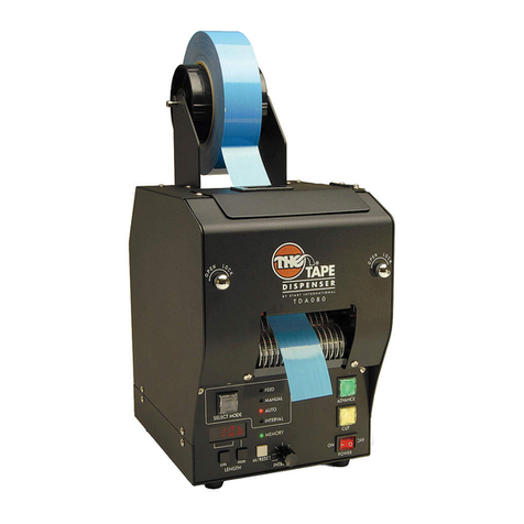
The DL-480 is a versatile ticket dispenser. It has both a 4 wire DL-1275 style input and a 6 pin DL-4 style
input. Each input can be independently configured to adjust the ticket payout. The inputs can be
configured to either multiply or divide the payout by a set factor, or to give a fixed quantity of tickets
instead of the normal payout.
Pins 3 and 4 of the DL-4 input can be connected to a coin switch to dispense “mercy tickets” while also
using the DL-1275 input to dispense earned tickets.
The DL-480 inputs and outputs can also be individually configured to use standard or inverted polarity.
Configuration
The DL-480 has 2 push buttons and a set of 4 DIP switches that are used to configure it. Configuration
settings are not changed until the entire procedure is completed. If you make a mistake, remove and
reapply power, and then start over.
1. Connect the DL-480 to the game. Then apply power.
2. To enter programming mode. Press both buttons the same time. The LED will come on.
3. Set the DIP switches for the motor speed as seen by the game and the adjustment mode for the DL-
1275 style input (see Table 1). Most games can use high speed, but some older games may require
standard speed.

2 July 2013
Table 1: Adjustment Mode for DL-1275 Input
1
2
3
4
Mode
Motor Speed
OFF
OFF
OFF
OFF
MULTIPLY
High
on
OFF
OFF
OFF
DIVIDE –round down (drop remainder)
High
OFF
on
OFF
OFF
DIVIDE –keeps remainder
High
OFF
OFF
on
OFF
DIVIDE –round up
High
on
on
OFF
OFF
FIXED
High
OFF
OFF
OFF
on
MULTIPLY
Standard
on
OFF
OFF
on
DIVIDE –round down (drop remainder)
Standard
OFF
on
OFF
on
DIVIDE –keeps remainder
Standard
OFF
OFF
on
on
DIVIDE –round up
Standard
on
on
OFF
on
FIXED
Standard
OFF = switch open, on = switch closed.
4. Press either button to read the DIP switches. If the switch setting is valid the LED starts slowly
blinking. If it does not start blinking check the switches and press the button again.
5. Set the DIP switches for the adjustment mode for the DL-4 style input.
Table 2: Adjustment Mode for DL-4 Input
1
2
3
4
Mode
OFF
OFF
OFF
x
MULTIPLY
on
OFF
OFF
x
DIVIDE –round down (drop remainder)
OFF
on
OFF
x
DIVIDE –keeps remainder
OFF
OFF
on
x
DIVIDE –round up
on
on
OFF
x
FIXED
OFF = switch open, on = switch closed, x = either (not used).
6. Press either button to read the DIP switches. If the switch setting is valid the LED will stop blinking.
If it does not stop, check the switches and press the button again.
7. Set the DIP switches for the adjustment value to use for the DL-1275 input (see Table 3). Be sure to
use the column in that corresponds to the adjustment mode you selected in step 3.
Table 3: Adjustment Value for DL-1275 Input
1
2
3
4
Multiply
Mode
Divide
Modes
Fixed
Mode
OFF
OFF
OFF
OFF
0
2
1
on
OFF
OFF
OFF
1
3
2
OFF
on
OFF
OFF
2
4
3
on
on
OFF
OFF
3
5
4
OFF
OFF
on
OFF
4
6
5
on
OFF
on
OFF
5
7
6
OFF
on
on
OFF
6
8
7
on
on
on
OFF
7
9
8
OFF
OFF
OFF
on
8
10
9
on
OFF
OFF
on
9
11
10
OFF
on
OFF
on
10
12
11
on
on
OFF
on
11
13
12
OFF
OFF
on
on
12
14
13
on
OFF
on
on
13
15
14
OFF
on
on
on
14
16
15
on
on
on
on
15
17
16
OFF = switch open, on = switch closed.
8. Press either button to read the DIP switches. The LED will start blinking slowly.
9. Set the DIP switches for the adjustment value to use for the DL-4 input (see Table 4). Be sure to use
the column in that corresponds to the adjustment mode you selected in step 5.

3 July 2013
Table 4: Adjustment Value for DL-4 Input
1
2
3
4
Multiply
Mode
Divide
Modes
Fixed
Mode
OFF
OFF
OFF
OFF
0
2
1
on
OFF
OFF
OFF
1
3
2
OFF
on
OFF
OFF
2
4
3
on
on
OFF
OFF
3
5
4
OFF
OFF
on
OFF
4
6
5
on
OFF
on
OFF
5
7
6
OFF
on
on
OFF
6
8
7
on
on
on
OFF
7
9
8
OFF
OFF
OFF
on
8
10
9
on
OFF
OFF
on
9
11
10
OFF
on
OFF
on
10
12
11
on
on
OFF
on
11
13
12
OFF
OFF
on
on
12
14
13
on
OFF
on
on
13
15
14
OFF
on
on
on
14
16
15
on
on
on
on
15
17
16
OFF = switch open, on = switch closed.
10. Press either button to read the DIP switches. The LED will blink faster.
11. Set the DIP switches for signal polarities and security (see Table 5). Then press either button to read
the DIP switches. The polarities feature allows the DL-480 to be used with games which use non-
standard signal polarities to prevent their use with standard ticket dispensers.
Table 5: Polarities and Security
Function
DIP Switch
OFF (open)
ON (closed)
Enable Signal Polarity
1
Standard
Reverse
Notch Signal Polarity
2
Standard
Reverse
DL-4 Polarity
3
Standard (N.O.)
Reverse (N.C.)
Ticket Feed Security
4
Inactive
Active
Pressing either button runs the motor to aid in loading tickets. In some applications this is a security
problem. Creative thieves have found a way to reach the buttons and use them to dispense
unearned tickets. When ticket feed security is active, the buttons do not work for feeding tickets.
See the description of Help mode for the exception to this.
Help Mode
If the DL-480 detects a problem it enters Help mode. In Help mode the LED blinks quickly. The most
common problem is running out of tickets. After fixing the problem, press either button. As long as
power to the game was not removed the DL-480 will then dispense any tickets that are owed.
Ticket feed security is overridden when in Help mode so that tickets can be easily reloaded. This
override expires two minutes after the first button press.
While in Help mode the DL-480 returns signals to the game so that the game does not enter an error
mode. If the game does detect an error then the DL-480 is hooked up incorrectly.
For technical help call (215) 997-8616.

4 July 2013
Table of contents