IPG Better Pack 555e Series User manual

Better Packages Safety Notice
2
This manual is a non-controlled document.
This manual has been carefully compiled and checked for accuracy. Information in this manual does not constitute a
warranty of performance. Furthermore, Better Packages reserves the right to revise this publication and make changes
from time to time, in its content.
Better Packages ASSUMES NO LIABILITY WHATSOEVER FOR ANY LOSSES OR DAMAGES INCURRED AS A
RESULT OF INFORMATION CONTAINED IN THIS MANUAL.
Proprietary Notice
This publication contains information proprietary and confidential to Better Packages. Any reproduction, disclosure, or
use of this publication is expressly prohibited except as Better Packages may otherwise authorize in writing.
Better Packages, Inc.
4 Hershey Drive
Ansonia, CT 06401
Telephone: 800/237-9151 (US Only)
203/926-3700 Fax: 203/926-3706
Web Site: http://www.betterpackages.com
CAUTION: If an object falls into one of the cover guide arm slots, disconnect power and notify service personnel.
CAUTION: Metal surfaces of the heater may attain temperatures up to 74 degrees Celsius (165 degrees Fahrenheit).
CAUTION: This equipment generates, uses, and can radiate radio energy and, if not installed and used in
accordance with the instruction manual, may cause interference to radio communications. It has been tested and
found to comply with the limits for Class A computing device pursuant to Subpart J of Part 15 of FCC Rules, which
are designed to provide reasonable protection against such interference when operated in a commercial
environment. Operation of this equipment in a residential area is likely to cause interference, in which case the user,
at his own expense, will be required to take whatever measures may be required to correct the interference.
CAUTION: When moving the tape dispenser from one location to another, power must be disconnected and the
water bottle, water tank and brushes should be removed to prevent spillage that could result in an electrical shock
hazard.
NOTE: Power must be removed before attempting to clear a tape jam.
NOTE: The top cover is interlocked such that the unit will not operate if the cover is not fully closed.

Better Packages Table of Contents
3
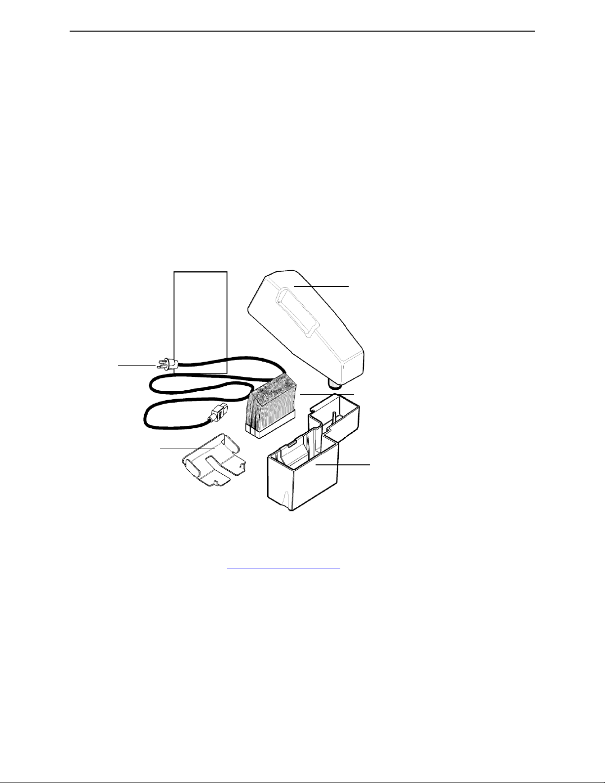
Section 1 - Unpacking and Setup
Unpacking...................................................................................................................................5
Checking the Contents................................................................................................................5
Fill Out the Warranty Card ..........................................................................................................5
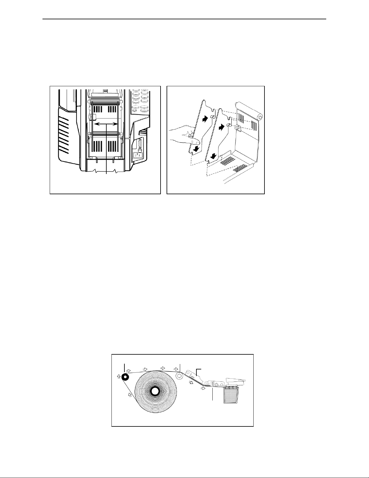
Adjusting the Roll Guides............................................................................................................5
Loading the Tape........................................................................................................................6
Checking Upper Tape Plate........................................................................................................7
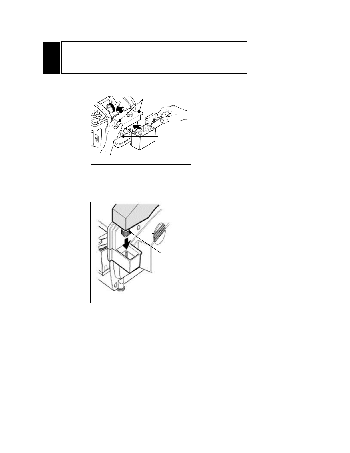
Installing the Bottle and Water Tank............................................................................................8
Mount the Dispenser to the Work Bench (Optional) ..................................................................10
Attach the Power Cord..............................................................................................................10
Section 2 -Detailed Operation
Turn the System “ON”...............................................................................................................12
Adjust the Setting on The Heater Assembly..............................................................................12
Select the Tape Length (Standard Model).................................................................................13
Select the Tape Length (Automatic Model) ...............................................................................14
To Dispense a Random Length of Tape....................................................................................14
To Dispense a Length of Tape Equal to a Number Button Length.............................................15
To Dispense a Specific Length Not on a Number Button...........................................................15
To Dispense Tape Longer Than the Amount on a Number Button...........................................15
To Dispense Tape Shorter Than the Amount on a Number Button...........................................15
To Dispense a Length of Tape Twice the Length of a Number Button......................................16
To Adjust the Length of a Number Button and Then Double It .................................................16
To Repeat the Length Previously Dispensed (Standard Model)...............................................17
To Repeat the Length Previously Dispensed (Automatic Model)...............................................17
To Activate Automatic Mode .....................................................................................................18
To Repeat One Tape Length Automatically...............................................................................18
To Repeat Two Tape Lengths Automatically.............................................................................18
To Repeat Three Tape Lengths Automatically ..........................................................................19
Section 3 - Sealing with Gummed Tape
Choosing the Best Tape for Your Application............................................................................20
Advantages of Water-Activated Tape........................................................................................20
Identifying the Types of Tape....................................................................................................20
What You Should Know About Adhesive Formulas...................................................................21
The Different Grades (Weights) of Sealing Tape.......................................................................21
Selecting Tape..........................................................................................................................21
Proper Tape Moistening............................................................................................................22
Adjusting the Amount of Water Applied to the Tape..................................................................22
Setting Heater Controls.............................................................................................................22
Choosing the Correct Tape Length ...........................................................................................23
Applying Tape to the Carton......................................................................................................23

Better Packages Table of Contents
4
Section 4 –Maintenance
Washing the Tank, Brushes, and Bottle....................................................................................24
Cleaning the Shear Blades .......................................................................................................25
Suggested Preventative Maintenance Schedule.......................................................................25
Clearing Jams...........................................................................................................................26
Changing the Fuse....................................................................................................................27
Lubrication................................................................................................................................28
Cleaning....................................................................................................................................29
Section 5 –Specifications
Model Descriptions ...................................................................................................................30
Technical Specifications............................................................................................................30
Port Connectivity.......................................................................................................................30
Connector Configurations……………………………………………………………...………………30
Model Types………………………………...…………………………………………...………………31
Section 6 -Service and Warranty
This section provides warranty information and how to obtain service.
Limited Warranty Statement......................................................................................................32
Index.........................................................................................................................................33

Better Packages Section 1
Unpacking and Setup
5
UNPACKING
When you open the top flaps on the box for the tape dispenser, there will be instructions for removing the
tape dispenser from its packaging. Save the box and packing materials in case you need to ship the unit
at some future time.
CHECKING THE CONTENTS
Packaged inside the tape dispenser, under the top cover are the following items: See Figure 1.
• Brush Assembly (three beveled brushes assembled together)
• Water Tank (a black plastic piece with a metal bracket attached to it)
• Water Bottle (a white plastic bottle with a screw cap)
• Upper Tape Plate
• Power Cord
• Operating Guide
• Warranty Card (inside the Operating Guide)
• 2 Tape Roll Guides (not pictured, see page 6)
FIGURE 1 - Checking Package Contents
FILL OUT THE WARRANTY CARD
Filling out the warranty card and returning it to us protects your warranty and allows us to keep you
informed of product upgrades. Visit www.betterpackages.com to fill out the warranty card online.
Preparing the Unit for Operation
ADJUSTING THE ROLL GUIDES
Roll guides fit into slots in the front and bottom panels of the tape basket. They hold the tape roll vertical
to allow the tape to unwind. You must adjust these guides for the size of the tape being used.
NOTE: This machine can dispense tapes from 1-½” to 3.0” wide.
Water Bottle
Brush
Assembly
Water Tank
Upper
Tape
Plate
Power Cord
Operating
Guide

Better Packages Section 1
Unpacking and Setup
6
Procedure:
1. Remove a guide from its current position by grasping the guide, lifting it up and pulling the bottom of it
to the rear of the unit. See Figure 2.
2. Reinsert each guide pressing it first into the front slot and then into the bottom slot. See Figure 3.
FIGURE 3
• Set the space between the guides to just larger than the width of the tape.
•Use the guides to center the tape as much as possible by inserting each guide into a slot the same
distance from the outside edge of the panel. For example, if you set the bottom part of the guide in the
second slot from the outside edge of the panel, set the front part of the guide also into the second slot from
the outside edge.
LOADING THE TAPE
1. Cut the end of the tape so that it has a clean, square end to feed under the
drive wheel.
2. Load the tape roll into the basket so that:
•The adhesive side is down.
•The roll is upright between the roll guides. See Figure 4.
•The end of the tape goes over the:
- Top of the tape roll from back to front.
- Lift Roller then rubber Roller
•The end of the tape is fed under the top tape plate and drive wheel; and is
butted against the shear blade.
3. Close the top cover.
Feed the tape:
• Adhesive side down
• Around the lift roller
• Over the black roller
• Under the upper tape plate
• Under the guide bar
• Up against the shear blade
FIGURE2 - Removingthe Guides from the Slots
Insert all four tabs the same number of
slots from theoutside edge.
ROLL GUIDES
Lift Roller
Black Roller
Upper Tape Plate
Shear
Blade
FIGURE4 - Loading the Tape Roll

Better Packages Section 1
Unpacking and Setup
7
The Upper tape plate must fit:
- Around the drive wheel
- Under the guide bar
- Over the rubber roller Drive Wheel
CHECKING UPPER TAPE PLATE
Make sure the upper tape plate is in its proper position as shown in Figure 6. If the plate is not correctly
positioned:
1. Hold the upper tape plate by its rear edge, See Figure 7, and guide it forward so that the front slot
centers around the drive wheel.
2. When the cutouts in the sides of the plate are above the retaining buttons, drop the plate down and
slide it forward as far as it will go.
NOTE: There is a round guide bar just before the cutting blade. The front of the upper tape plate should
be under that guide bar.
Drive Wheel
FIGURE 6 - Upper Tape Platein
ProperPosition
Drive Wheel
Guide
Bar
FIGURE 7 –Positioning
theUpper TapePlate
Upper
Tape
Plate

Better Packages Section 1
Unpacking and Setup
8
Brushes must be angled toward the
front of the dispenser in order to work.
Installing the brushes backwards will
cause a troublesome tape jam.
INSTALLING THE BOTTLE AND WATER TANK
1. Insert the brush assembly in the water tank. The brush assembly must be tilted toward the dispenser
so that the cotter pin will clear the retaining bracket as it is pressed into place. See Figure 8. Then rotate
the brush forward so that it seats flatly on the bottom of the water tank. The edge of the base of the brush
should be under the retaining bracket.
2. Lift the front of the heater assembly and slide the water tank into position at the front of the dispenser.
At first, tilt the brush toward the dispenser so that the head of the cotter pin clears the retaining bracket as
you push the brushes into the tank. Then tilt the brush back so that it seals flatly on the bottom of the
tank.
The bottom of the water tank should be even with the edges of the shelf it sits on and the water tank will
drop slightly into the shelf when it is correctly positioned.
3. Lower the heater assembly.
4. Fill the bottle with water.
FIGURE 8 -Inserting theBrush
into the Water Tank
Retaining bracket

Better Packages Section 1
Unpacking and Setup
9
5. Position the bottle onto the right side of the dispenser. The spring-loaded center of the bottle’s cap
must be on the pylon protruding up from the water tank. See Figure 10.
CAUTION: Under normal operating conditions, the bottom of the
heater assembly may be HOT. Handle the assembly ONLY by the
tabs sticking out from the sides. See Figure 9.
!
FIGURE 9 - Handling the Heater Assembly
The tank will
drop slightly
into this
shelf when it
is correctly
positioned
Use these tabs to raise
and lower the heater
assembly
FIGURE 10 - Attaching the
Bottle to the Dispenser
Bottle
normally
fits in this area
Center of the
bottle cap fits
over the pylon
in the tank

Better Packages Section 1
Unpacking and Setup
10
MOUNT THE DISPENSER TO THE WORK BENCH (OPTIONAL)
The dispenser may be bolted to the work bench or table that it sits on. The main reason to do this is the
dispenser can’t be knocked off the bench-top should someone bump into it. The dispenser is shipped with
four (4) rubber feet attached to the bottom panel by 10-24 Phillips head screws.
1. Drill four holes into the top of the bench.
2. Remove the screws and washers from the bottom panel that hold the feet
in place.
3. Measure the thickness of the bench top. Obtain 4 (four) 10-24 screws/bolts that are 9/16” to 1-1/16”
longer than the thickness of the bench top. For example, if the bench top is 1” thick, use screws 1-9/16” to
2-1/16” long to attach the dispenser to the bench top.
4. Position the dispenser over the bench so that their mounting holes are lined up.
IMPORTANT: Keep the feet between the dispenser and the bench top. This will protect both the
dispenser and the bench from vibration from the dispenser’s normal operation.
5. Insert the 10-24 screws through the bottom of the bench, through the rubber feet, into the threaded
holes in the bottom panel. See Figure 11.
• Use Loctite®or a similar thread locking compound on the threads of the screws to prevent them from
loosening.
• Tighten the screws until they are snug, but do not tighten them so much that the rubber feet are
compressed.
• Use washers under the heads of the bolts or screws used to secure the dispenser to the bench top.
ATTACH THE POWER CORD
1. Ensure that the power switch is in the OFF (down) position. See Figure 12.
2. Attach the female end of the power cord to the dispenser connector.
See Figure 13.
FIGURE 11 -Mounting the Dispenser to a Bench Top
Use the feet supplied with the dispenser.
Top of bench or table.
FIGURE 12 –PowerSwitch Location

Better Packages Section 1
Unpacking and Setup
11
There are two other components on the electrical panel:
•The 9-Pin female connector that can be used:
On Standard and Automatic models to attach a pedal switch. On Automatic models (only) to access an
RS-232 serial data port. Using this data port, the Better Packages Automatic Measuring Device (AMD-1)
(purchased separately) can be utilized to instantly measure & dispense the exact length as tape needed.
•A user-replaceable fuse.
See the Maintenance Section
3. Plug the male end of the power cord into a 110/120v 60hz receptacle.
If you are not sure if the electrical system in your building is properly grounded, contact a licensed
electrician.
FIGURE 13 –The Electrical Panel
Use this
port for
optional
pedal
control
or AMD-1
Fuse
Holder
Attach
the A/C
Power
Cord
here
WARNING: FOR YOUR SAFETY
All metal parts of this machine are
electrically grounded through a
3-wire power supply. You must plug
this cord into a 3-wire grounded type
receptacle.
!

Better Packages Section 2
Operation
12
TURN THE SYSTEM “ON”
Turn the power switch to the “ON” (up) position. The switch will light and the dispenser will “beep” once.
See Figure 14.
ADJUST THE SETTING ON THE HEATER ASSEMBLY
Finding the correct setting for the tape you are using is a matter of simple testing. Turn adjustment knob
to highest setting (clockwise), then back off slightly to the lowest temperature setting that best meets your
needs. See Figure 15. Refer to Section 3 “Sealing with Gummed Tape”.
When the heat is properly adjusted, the tape will adhere quickly to the parcel. Too low a setting may
result in the tape taking slightly longer to properly adhere.
FIGURE 14 -On/Off Switch Location
FIGURE 15 - Handling the Heater Assembly
Temperature Adjustment Control Knob
CAUTION: The bottom of the heater assembly gets HOT!
Handle the heater only by the tabs protruding from the sides
of its top. See Figure 15.
!

Better Packages Section 2
Operation
13
SELECT THE TAPE LENGTH (STANDARD MODEL)
Pressing a button or combination of buttons allows you to dispense tape in lengths from 4” to a maximum
of 120” in increments of ½”. See Figure 16a.
FIGURE 16a - Keypad for Tape LengthSelection
PLUS Button Adds ½” (1 cm)
to selected length
MINUS Button Subtracts ½”
(1 cm) from selected length
REPEAT START Button
Repeats length selected before
this button was pressed
X2 Button Doubles selected length
Manual Feed Button Dispenses
tape while pressed. Length (4” to
120”) is determined by how long
the button is held
Number Buttons Select length
of tape

Better Packages Section 2
Operation
14
SELECT THE TAPE LENGTH (AUTOMATIC MODEL)
Pressing a button or combination of buttons allows you to dispense tape in lengths from 4” to a
maximum of 120” in increments of ½”.
See Figure 16b.
TO DISPENSE A RANDOM LENGTH OF TAPE:
Press and hold the manual feed button (down arrow) until the desired length of tape is dispensed.
It will dispense a length of 4” (10 cm) to a maximum of 120” (305 cm) depending upon how long the
button is held down.
FIGURE 16b - Keypad for Tape Length Selection
PLUS Button Adds ½” (1 cm)
to selected length
MINUS Button Subtracts ½”
(1 cm) from selected length
REPEAT START Button
Repeats length selected before
this button was pressed
A Button Press to place the unit in
Automatic mode (light will be “on”
when unit is in automatic mode)
Number Buttons Select length
of tape
X2 Button Doubles selected length
Manual Feed Button Dispenses
tape while pressed. Length (4” to
120”) is determined by how long
the button is held
REPEAT 2 ENTER Button
Used for a 2nd length or preset
length.
The Manual Feed Button
(lower right on the keypad)

Better Packages Section 2
Operation
15
TO DISPENSE A LENGTH OF TAPE EQUAL TO A NUMBER BUTTON LENGTH:
Press To dispense 42”
Press To dispense 15”
TO DISPENSE A SPECIFIC LENGTH NOT ON A NUMBER BUTTON:
• You can add or subtract ½” increments from any number button length.
• You can double any button number length.
• You can adjust a number button length (longer or shorter) and then double it.
• You can repeat the length previously dispensed with a single button.
ERROR NOTIFICATION
NOTE: If you press a combination of keys that doesn’t work, the system lets you know by beeping three
times. If this happens, re-enter the key or combination of keys to produce the length or lengths that you
require.
TO DISPENSE TAPE LONGER THAN THE AMOUNT ON A NUMBER BUTTON:
Press To dispense 42-½”
(one ½” is added for each press of the button).
In this case it is ½” (1 x ½”).
Press To dispense 43” (one ½” is added for each
press of the button.
In this case it is 1” (2 x ½”).
Press the button once for each ½”you want to add to a number button.
You can press the button as many times as you want before you press the number button. For
example;
•To dispense 42-½” of tape, press the button once (to add ½”) and then
press the button. A 42-½” length of tape is dispensed.
TO DISPENSE TAPE SHORTER THAN THE AMOUNT ON A NUMBER BUTTON:
Press To dispense 41-½”
(one -½” is subtracted for each press of the button).
In this case it is 1/2” (1 x ½”).
Press To dispense 41”
(one ½” is subtracted for each 1” press of the button).
In this case it is 1” (2 x ½”).

Better Packages Section 2
Operation
16
Press the button once for each ½” you want to subtract from a number button. For example:
•To dispense 41-½” of tape, press the button once (to subtract ½”) and
then press the button. A 41-½” length of tape is dispensed.
•To dispense 41” of tape, press the button twice (to subtract one inch) and
then press the button. A 41” length of tape is dispensed.
•You can press the button as many times as you want before you press the number button.
TO DISPENSE A LENGTH OF TAPE TWICE THE LENGTH OF A NUMBER BUTTON:
Press To dispense 84”. (2 times 42 = 84)
Press To dispense 54”. (2 times 27 = 54)
First press the button and then press the number button.
For example:
•Pressing and then pressing the button will dispense 84” of tape.
•Pressing and then pressing the button will dispense 54” of tape.
TO ADJUST THE LENGTH OF A NUMBER BUTTON AND THEN DOUBLE IT:
Press To dispense 63”, 30” plus 1½”
(for the three buttons) = 31-½”.
31-½” times 2 (for the button) = 63”.
The button can be used together with the button or the button to double the length of an
adjusted number button. For example;
•If you press the button three times (to add 11/2”), press the button, and then press the
number button, 63” of tape will be dispensed.

Better Packages Section 2
Operation
17
TO REPEAT THE LENGTH PREVIOUSLY DISPENSED (STANDARD MODEL):
The dispenser “remembers” the last length of tape dispensed and stores that value in its memory.
Pressing the REPEAT key dispenses the same length of tape that was previously dispensed. This is
especially handy if you are dispensing a tape length that was adjusted using the or the buttons.
The REPEAT key also repeats standard number button lengths. Each time you dispense a different length
of tape by pressing a different button or combination of buttons, that new figure:
• Is stored in the REPEAT button memory
• Becomes the length dispensed the next time you press the REPEAT button.
The REPEAT Button –
Lower left on the keyboard
TO REPEAT THE LENGTH PREVIOUSLY DISPENSED (AUTOMATIC MODEL):
The dispenser “remembers” the last two length of tape dispensed and stores those values in its memory.
STANDARD MODE:
To dispense a six inch tape press once. Remove the piece of tape.
Press this will also dispense a six inch tape.
Press and a nine inch piece of tape will be dispensed. Remove the piece of tape.
Press a nine inch piece of tape will again be dispensed.

Better Packages Section 2
Operation
18
Remove the piece of tape, press a six inch piece of tape will be dispensed.
In this way, any two lengths can be memorized by the unit's electronics and can be repeated using:
AUTOMATIC MODE:
In the Automatic Mode, removing a piece of tape from the dispenser causes another piece of tape to be
dispensed automatically. Additionally, in the Automatic Mode, the dispenser can remember up to three
tape lengths and automatically dispense them in the order in which they were entered.
TO ACTIVATE AUTOMATIC MODE:
1) Make sure that the last piece of tape dispensed has been removed.
2) Press (A button)
3) The indicator will be illuminated (red).
TO REPEAT ONE TAPE LENGTH AUTOMATICALLY:
Press ... a six inch tape will be dispensed. Remove the six inch tape.
Press
Press
A six inch piece of tape will be dispensed. Remove it and another six inch piece of tape will be dispensed
automatically.
TO REPEAT TWO TAPE LENGTHS AUTOMATICALLY:
First make sure the memory is clear of any lengths previously stored. To do this, press “A”, the indicator
turns off. Remove any piece of tape that may have been dispensed but not removed. Press “A” again.
The indicator lights (red) and the memory is cleared and ready for your input.
Press ... a six inch tape will be dispensed. Remove the six inch tape.
Press
Press ... a nine inch tape will be dispensed. Remove the nine inch piece of tape.
Press
Press
A six inch piece of tape will be dispensed. Remove the six inch piece of tape and a nine inch piece will
automatically be dispensed. Removing the nine inch piece will then automatically dispense a six inch
piece.

Better Packages Section 2
Operation
19
TO REPEAT THREE TAPE LENGTHS AUTOMATICALLY:
First make sure the memory is clear of any lengths previously stored. To do this, press “A”, the indicator
turns off. Remove any piece of tape that may have been dispensed and not removed. Press “A” again.
The indicator lights (red) and the memory is cleared and ready for your input.
Press ... a six inch tape will be dispensed. Remove the six inch tape.
Press
Press ... a nine inch tape will be dispensed. Remove the nine inch piece of tape.
Press
Press ... a twelve inch tape will be dispensed. Remove the twelve inch piece of tape.
Press
Press
A “6” inch piece of tape will be dispensed and as each successive piece is removed the unit automatically
continues to dispense in the correct sequence: … 9, 12, 6, 9, 12, 6, 9, 12 … and so on.

Better Packages Section 3
Sealing with Gummed Tape
20
CHOOSING THE BEST TAPE FOR YOUR APPLICATION
Depending on its type and manufacturer, water-activated tape is also called:
•Gummed paper tape
•Kraft tape
•Reinforced tape
•Reinforced paper tape
ADVANTAGES OF WATER-ACTIVATED TAPE:
•Strong, secure seal
•Neat appearance
•May be printed on during application
•Adheres well even in dirty, dusty environments
•Up to ten times stronger than plastic tape
•Doesn’t stick to itself during application
•Permanent bond formed when the adhesive penetrates the corrugated board
•Unaffected by extremes of cold, heat, light or humidity
•Even when damaged, it retains strength. It doesn’t run, tear, or stretch
•Tamper evident if the seal is compromised
•Environmentally friendly and recyclable
•Eliminates repetitive wrist motions of hand-held guns
•Discourages theft –tape won’t “pop off”
•Economical –never need more than one strip of tape per seal
IDENTIFYING THE TYPES OF TAPE
The following table lists the types of tape and their identifying characteristics:
TYPE
CHARACTERISTIC
Water-Activated or
Gummed Tape
Gummed adhesive on the back which must
be wet, or reactivated, by water
Paper Tape or
Kraft Paper Tape
Made from paper only, with no additional
reinforcing material
Reinforced Tape or
Reinforced Paper Tape
Same as paper tape, but also contains
strands of reinforcing material
Tapes are differentiated by:
•Their color –Kraft or white
•The weight of the paper used in the top and bottom sheets
•The presence of reinforcing material and the thickness, the number of
reinforcing strands and the weave pattern of the strands
•The glue formula
This manual suits for next models
2
Table of contents
Other IPG Dispenser manuals
Popular Dispenser manuals by other brands

Bartscher
Bartscher 191004 Original instruction manual

Fizz
Fizz Nitro-Draught ND0101 Installation, operation and service manual

Cecilware
Cecilware Radiance 5 Technical & service manual

Axor
Axor Starck Soap/Lotion Dispenser 40819XX0 Specification sheet

MTBL
MTBL Baijiu G4 quick start guide

LINDR
LINDR Green Line new CWP 100 instruction manual