Dema Electric D6 Series User manual

Thank you to choose inverter of DEMA Electric Co., Ltd.
D6 series inverter is the product developed by the DEMA Electric Co., Ltd, which is characterized with high
performance, multiple functions and high quality. They apply technology platform with high performance,
modular system structure and programmable units which make them with various application scope and
strong adaptability.
Errors in installation, wiring and operation may cause accidents, shorten the inverter’s life and degrade its
performance. Therefore the operators must carefully read and understand this manual before using the
inverter, master the right operation method.
This operation manual must be properly safekept by operator of the machine.
If you have any unclear problems during operation or excellent performance of the inverter isn’t played role,
please refer to this manual.
This manual is applicable to following members of D6 series:
D6B: General inverter with high functions, with open/close loop control, torque control and multiple-application
control mode (including PID, wobbling frequency etc), applicable to very extensive application field.
D6L: General light load type multi-functional inverter, open loop no PG vector control, applicable to light load
constant torque or fan pumps loading applications whose overload capacity demand isn’t high.
D6P: Flat plate through-wall installation type inverter, open loop no PG vector control, applicable to light load
constant torque or fan pumps loading applications whose overload capacity demand isn’t high.
Version number: 1.4
Date: 2013-10-24
DEMA electric cooperation is not responsible for the mistakes in this manual, and reserve the rights to renew
production without informing.
Attentions:
Please read this operation manual carefully, understand each contents, so that you can carry out right
installation, wiring, operation and maintenance.
Use inverter only after be familiar with knowledge, safe information and all attentions of the inverter..
This manual should be reserved by actual user.
The safety levels are divided into ―Danger‖ and ―Warning‖ in this manual, please use the following mark
respectively:
: It may cause death or serious injure of personnel if it isn’t operated according to
requirements.
: It may cause moderate damage or minor injuries of personnel, or property damage if it
isn’t operated according to requirements..
Please be sure to eep the contents marked with safety sign. Because the situation is different, items
marked by ―Warning‖ may also cause serious results, please follow these two level attentions.

English term and abbreviations
ASR: Automatic Speed Regulator
AVR: Automatic Voltage Regulation
AI: Analog Input
AO: Analog Output
DI: Digital Input
DO: Digital Output
EMI: Electric Magnetic Interference
LED: Light Emitting Diode
MOP: Motor Operated Potentiometer
PULS: Pulse Input
PYO: Pulse Frequency Output
PID: Proportional Integral Derivative
PG: Pulse Generator
PWM: Pulse Width Modulation
SVPWM: Space Vector Pulse Width Modulation
S.T.P: Speed, Torque, Position

Contents
1 SAFETY PRECAUTIONS ..............................................................................................................................................1
1.1 INSTALLATION........................................................................................................................................................1
1.2 WIRING..................................................................................................................................................................1
1.3 OPERATION............................................................................................................................................................1
1.4 MAINTENANCE ......................................................................................................................................................2
1.5 DISPOSAL...............................................................................................................................................................2
1.6 APPLICABLE SCOPE OF PRODUCT...........................................................................................................................2
2 INSTALLATION AND WIRING .....................................................................................................................................3
2.1 CHECK UPON DELIVERY..........................................................................................................................................3
2.2 NAMEPLATE DESCRIPTION.....................................................................................................................................3
2.3 TYPE DESCRIPTION ................................................................................................................................................3
2.4 INSTALLATION OF INVERTER ..................................................................................................................................4
2.4.1 AMBIENT CONDITION................................................................................................................................................. 4
2.4.2 INSTALLATION SITE..................................................................................................................................................... 4
2.4.3 INSTALLATION SPACE AND HEAT DISSIPATION .................................................................................................................... 4
2.4.4 APPEARANCE AND INSTALLATION SIZE............................................................................................................................ 5
2.5 REMOVAL AND INSTALLATION OF OPERATION KEYPAD .........................................................................................9
2.5.1 APPEARANCE AND SIZE OF OPERATION KEYPAD................................................................................................................. 9
2.5.2 APPEARANCE AND SIZE OF STANDARD OPERATION KEYPAD INSTALLATION BOX ......................................................................... 9
2.5.3 DIRECT INSTALLED TYPE OPERATION KEYPAD .................................................................................................................. 10
2.5.4 KEYBOARD INSTALLATION BOX WITH POTENTIOMETER AND RJ45 INTERFACE (OPTIONAL)........................................................ 10
2.5.5 INSTALLATION AND REMOVAL OF OPERATION KEYPAD ...................................................................................................... 11
2.5.6 INSTALLATION OF KEYPAD ON CABINET FRONT COVER....................................................................................................... 12
2.6 WIRING OF INVERTER ..........................................................................................................................................13
2.4.1 BASIC WIRING DIAGRAM OF INVERTER ......................................................................................................................... 13
2.4.2 WIRING SPECIFICATIONS ........................................................................................................................................... 14
2.4.3 MAIN CIRCUIT TERMINALS......................................................................................................................................... 15
2.4.4 CONTROL CIRCUIT TERMINALS.................................................................................................................................... 17
3 OPERATION DESCRIPTION OF INVERTER .................................................................................................................22
3.1 NAME AND DESCRIPTION OF EACH PART OF OPERATION PANEL .........................................................................22
3.1.1 APPEARANCE OF OPERATION PANEL............................................................................................................................. 22
3.1.2 DESCRIPTION OF KEY FUNCTION ................................................................................................................................. 22

3.1.3 DESCRIPTION OF LED DISPLAY FUNCTION......................................................................................................................22
3.1.4 UNITS INDICATION ...................................................................................................................................................23
3.1.5 RUN STATUS INDICATIONS..........................................................................................................................................23
3.2 DISPLAY STATUS OF OPERATION KEYPAD OF INVERTER ........................................................................................23
3.2.1 STOP STATUS ..........................................................................................................................................................23
3.2.2 RUN STATUS ...........................................................................................................................................................23
3.2.3 ABNORMAL STATUS..................................................................................................................................................24
3.2.4 PARAMETER EDITING STATUS ......................................................................................................................................24
3.2.5 PASSWORD CHECK STATUS .........................................................................................................................................24
3.3 OPERATION OF OPERATION PANEL ......................................................................................................................24
3.3.1 INVERTER MONITORING PARAMETERS SWITCH................................................................................................................24
3.3.3 SPEED ADJUST ........................................................................................................................................................25
3.4 OPERATION OF CONTROL TERMINALS .................................................................................................................25
3.4.1 STATUS MONITORING OF DIGITAL CONTROL TERMINALS ....................................................................................................25
3.4.2 RUN OPERATION .....................................................................................................................................................25
3.5 JOG RUN OPERATION MODE OF INVERTER ..........................................................................................................26
3.6 SWITCHING ON THE POWER FOR THE FIRST TIME................................................................................................26
3.7 COMMISSIONING GUIDE......................................................................................................................................26
3.7.1 SETTING COMMON PARAMETERS OF EACH CONTROL MODE...............................................................................................27
3.7.2 QUICK COMMISSIONING FOR V/F CONTROL OF ELECTRIC MOTOR .......................................................................................27
3.7.3 QUICK COMMISSIONING FOR VECTOR CONTROL OF ELECTRIC MOTOR ..................................................................................27
4 DESCRIPTION OF FUNCTION PARAMETERS AND SETTING .......................................................................................28
4.1 ENVIRONMENT AND PARAMETERS MANAGEMENT .............................................................................................28
4.2 SPEED (FREQUENCY) LIMITATION.........................................................................................................................31
4.3 BASIC FREQUENCY ...............................................................................................................................................31
4.4 V/F CURVE ...........................................................................................................................................................32
4.5 TORQUE COMPENSATION ....................................................................................................................................33
4.6 VECTOR CONTROL CURRENT LOOP AND ROTATION DIFFERENTIAL COMPENSATION ............................................34
4.7 START AND STOP..................................................................................................................................................34
4.8 ACCELERATION AND DECELERATION ....................................................................................................................37
4.9 LOCKING THE OPERATION DIRECTION..................................................................................................................39
4.10 SPEED DETECTION..............................................................................................................................................39
4.11 BRAKE UNIT .......................................................................................................................................................40
4.12 DANGEROUS SPEED ...........................................................................................................................................41
4.13 ANALOG INPUT TERMINALS...............................................................................................................................41
4.14 ANALOG OUTPUT TERMINALS ...........................................................................................................................45
4.15 DIGITAL INPUT TERMINALS ................................................................................................................................46

4.16 DIGITAL OUTPUT TERMINALS ............................................................................................................................51
4.17 TWO/THREE-LINE OPERATION CONTROL ...........................................................................................................54
4.18 SPEED CONTROL OPERATION MODE ..................................................................................................................56
4.19 TORQUE CONTROL OPERATION MODE ..............................................................................................................59
4.20 PROCESS PID CONTROL......................................................................................................................................63
4.21 WOBBLE FREQUENCY......................................................................................................................................... 68
4.22 ASR (SPEED REGULATOR AND CURRENT REGULATOR) .......................................................................................71
4.23 AVR FUNCTION ..................................................................................................................................................73
4.24 STALL PREVENTION ............................................................................................................................................ 74
4.25 THE DROOP MECHANICAL CHARACTERISTIC ...................................................................................................... 76
4.26 FAULT AUTO RESET ............................................................................................................................................77
4.27 CARRIER AND MODULATION .............................................................................................................................77
4.28 COOLING FAN CONTROL ....................................................................................................................................79
4.29 RESTART AFTER MOMENTARY POWER STOP......................................................................................................80
4.30 INVERTER AND MOTOR PROTECTION ................................................................................................................81
4.31 POWER LIMIT.....................................................................................................................................................84
4.32 MOTOR PARAMETERS AND AUTO-TUNING........................................................................................................84
4.33 SLIP FREQUENCY COMPENSATION .....................................................................................................................86
4.34 ENCODER ...........................................................................................................................................................86
4.35 PROGRAMMABLE UNIT......................................................................................................................................88
4.36 SERIAL COMMUNICATION .................................................................................................................................93
4.37 MULTI-MODE PLC PARAMETERS ........................................................................................................................94
5 SERIAL COMMUNICATION PROTOCOL.....................................................................................................................98
5.1 GENERAL DESCRIPTION........................................................................................................................................98
5.2 MODBUS FUNCTIONS SUPPORTED BY THE DRIVE................................................................................................98
5.3 TABLE OF COMMUNICATION VARIABLES............................................................................................................ 102
6 INVERTER MAINTENANCE.....................................................................................................................................106
6.1 DAILY MAINTENANCE ........................................................................................................................................ 106
6.2 PERIODICAL MAINTENANCE .............................................................................................................................. 106
6.3 INSULATION TEST .............................................................................................................................................. 107
6.4 REPLACEMENT OF PARTS ................................................................................................................................... 107
7 INVERTER OPERATION FAULTS AND REMEDIES ..................................................................................................... 109
7.1 OPERATION FAULTS AND REMEDIES................................................................................................................... 109
7.2 INVERTER FAULT DISPLAY AND REMEDIES..........................................................................................................109
8 PERIPHERAL DEVICES............................................................................................................................................ 114
8.1 CONNECTING DIAGRAM OF PERIPHERAL DEVICES ............................................................................................. 114
8.2 DESCRIPTION OF ACCESSORIES .......................................................................................................................... 115

8.2.1 NOISE FILTER........................................................................................................................................................115
8.2.2 CURRENT-LEAK PROTECTOR......................................................................................................................................115
8.2.3 BRAKING RESISTOR ................................................................................................................................................115
8.2.4 AC REACTOR ........................................................................................................................................................116
8.2.5 DC REACTOR ........................................................................................................................................................116
8.2.6 EXTENDED CABLE ..................................................................................................................................................117
9 STANDARD SPECIFICATIONS ..................................................................................................................................118
9.1 STANDARD SPECIFICATIONS ...............................................................................................................................118
9.2 COMMON FEATURE ........................................................................................................................................121
10 FUNCTION PARAMETER ......................................................................................................................................123
11 GUARANTEE AND SERVICE ..................................................................................................................................158
PROTECTION TO FIX CARD .......................................................................................................................................159
1 Safety Precautions
1
1 Safety Precautions
You must carefully read the following contents before installation, wiring, operation and maintenance of the
product, and operate strictly according to notes.
1.1 Installation
Install the inverter on a nonflammable object such as metal etc. Otherwise, there may be a risk of fire.
Do not install the inverter in an environment with inflammable gases which may cause explosion.
Install the inverter firmly on an object capable of bearing its weight. Otherwise, the falling of the inverter may cause injury or
damage of human or equipment..
Do not drop any metal foreign matter in the inverter. Otherwise, accident may occur.
Do not install or run the inverter if it is damaged. Otherwise, accident may occur.
1.2 Wiring
Connect a proper circuit-breaker which matches capacity of the inverter on the input power side of the inverter. Otherwise,
human injury, equipment damage or other accident may occur.
The PE terminal of the inverter must be grounded securely. Otherwise, electric shock or fire may occur.
Tighten up power input terminal of power supply and motor input terminal screw. Otherwise, there may be a fire accident.
The wiring must be done by a qualified personnel.
The wiring must be done after the power is cut off and the high-voltage indicator extinguishes.
The input power must conform to the specifications on the nameplate. Otherwise, the inverter may be damaged.
Never connect the output terminals (U, V, W) to the input power. Otherwise it may destroy the inverter.
1.3 Operation
1 Safety Precautions
2
Only when the cover board has been attached, the power can be switched on. Otherwise, there may be a risk
of electric shock.
Do not touch main circuit terminal of the inverter when electrical power is going to the inverter even if the
inverter is in stop state. Otherwise, there may be a risk of electric shock.
Us operation panel ―STOP/RESET‖ key and external controlled terminal to stop the inverter, but not break the main power
supply. otherwise, the inverter may be damaged.
1.4 Maintenance
10 minutes after power is switched off, the inverter can be inspected and repaired. Otherwise, there may be a risk of electric
shock or injury.
Only professional person can maintain the inverter. Otherwise, electric shock or injury may occur.
Do not leave any conductor such as metals in the inverter after repairing it. Otherwise, the inverter may be damaged.
While an inverter which has not been used for a long period is used again, use a voltage regulator to charge the input voltage
gradually until it reaches the rated value, and wait for a while and confirm it is safe. Otherwise, accident may occur.
1.5 Disposal
When the product is discarded, dispose it as an industrial waste. Otherwise, accident may occur.
1.6 Applicable scope of product
Not apply to the machine or system which may cause life danger of human .
If this product is expected to abnormality of this product will occur a major accident or loss, please be sure to add safety device.
2 Installation and Wiring
3
2 Installation and Wiring
2.1 Check upon delivery
Please check the following items when the inverter is firstly packed:
◆ Whether the product is damaged during shipping.
◆ Read data on the nameplate conform whether type and specification of the product are in accordance with
your order.
◆ Check whether the accessories shipped together with the inverter are complete.
The company strictly develops and manufactures the inverter according to ISO9001, if found to have some
unusual, please contact and agent or agent as soon as possible.
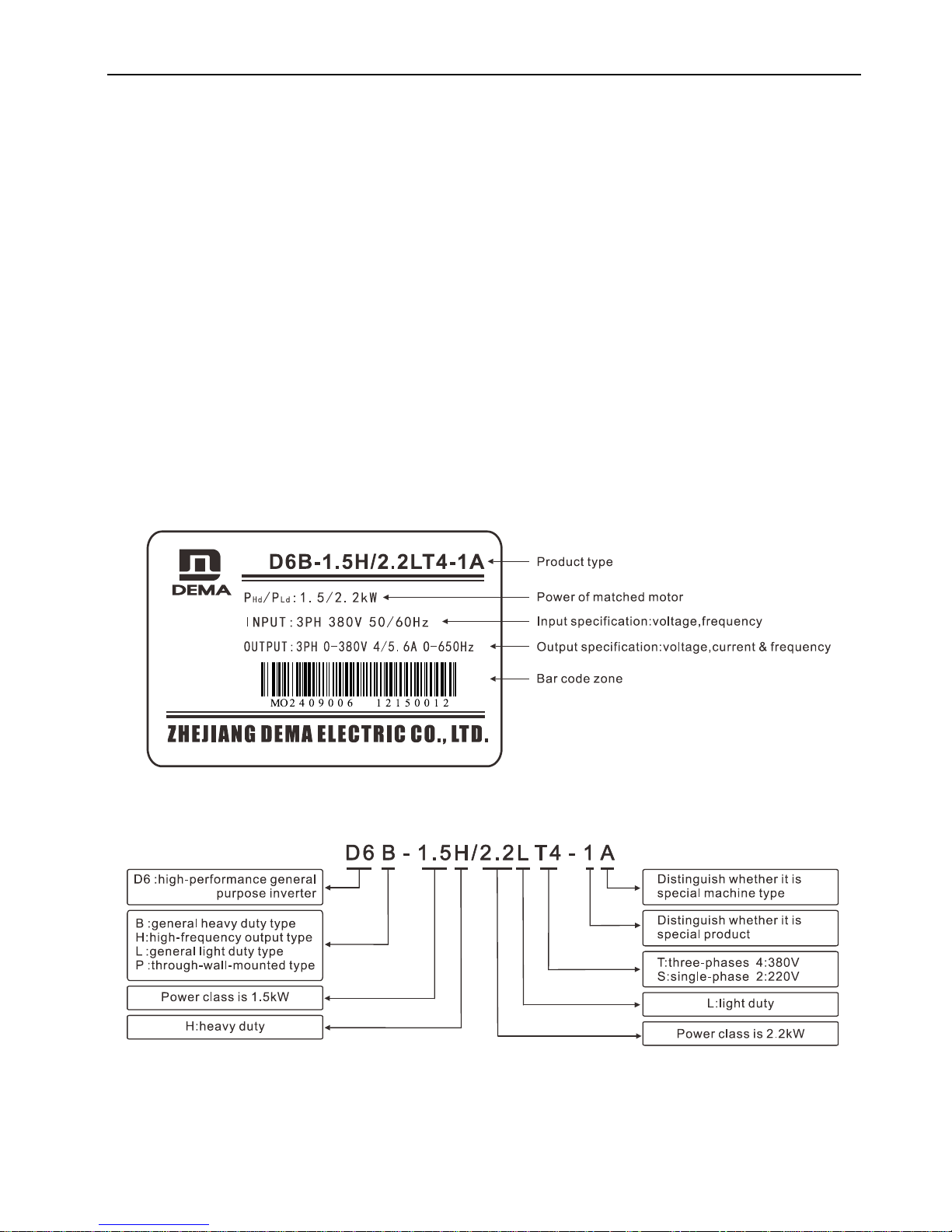
2.2 Nameplate description
2.3 Type description
2 Installation and Wiring
4
2.4 Installation of inverter
2.4.1 Ambient condition
Environment temperature range of inverter: -10℃~50℃. When the ambient temperature is higher than
50℃, please choose well ventilated place and decrease the inverter by 10% for every 5℃ increment.
2.4.2 Installation site
◆No corrosive, flammable or explosive gases or liquids.
◆Humidity: less than 90% RH, no condensation.
◆Vibration: less than 5.9m/s2 (0.6g)
◆Avoid installing it at a place with much dust and metal powder
If users have special installation requirements, please consult and confirm with manufacturer in advance.
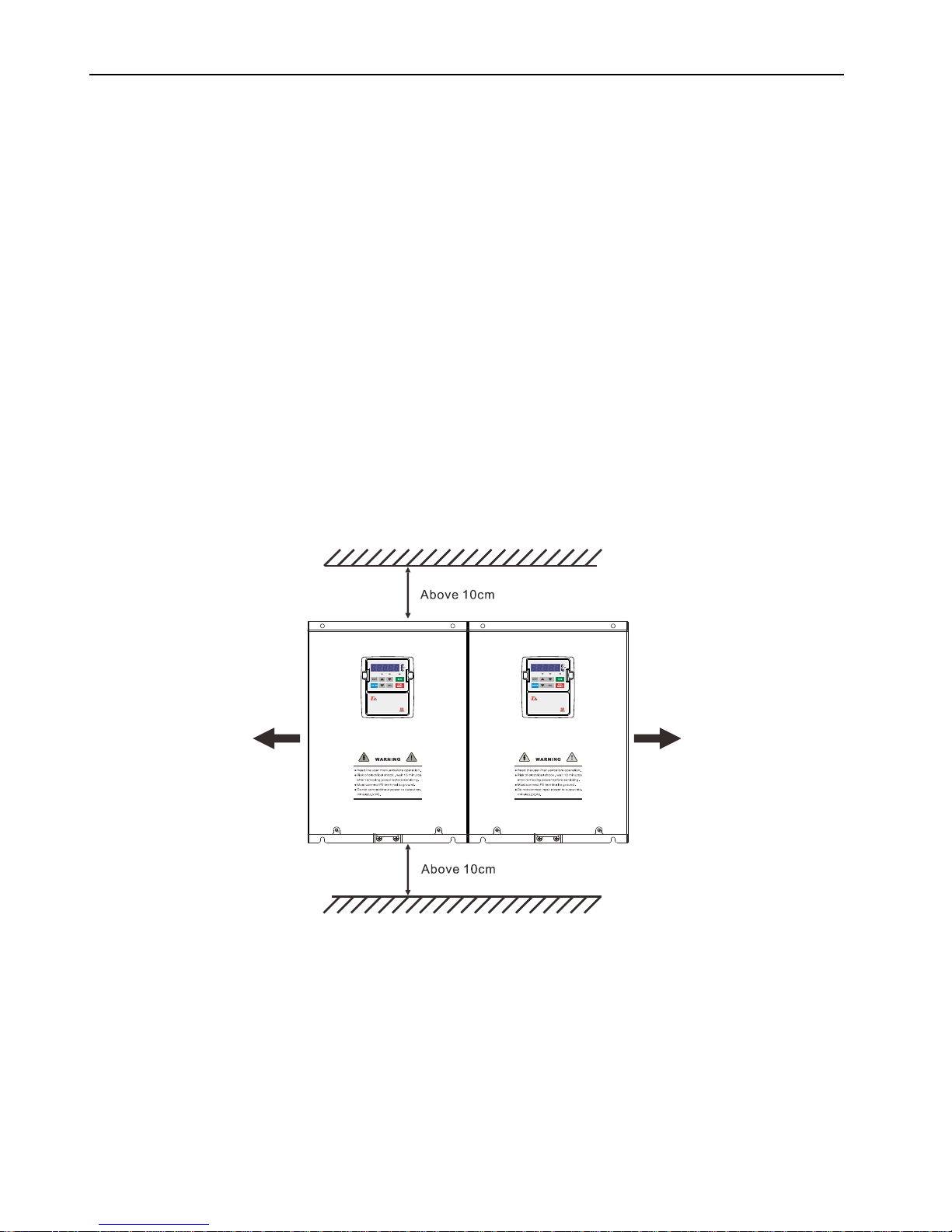
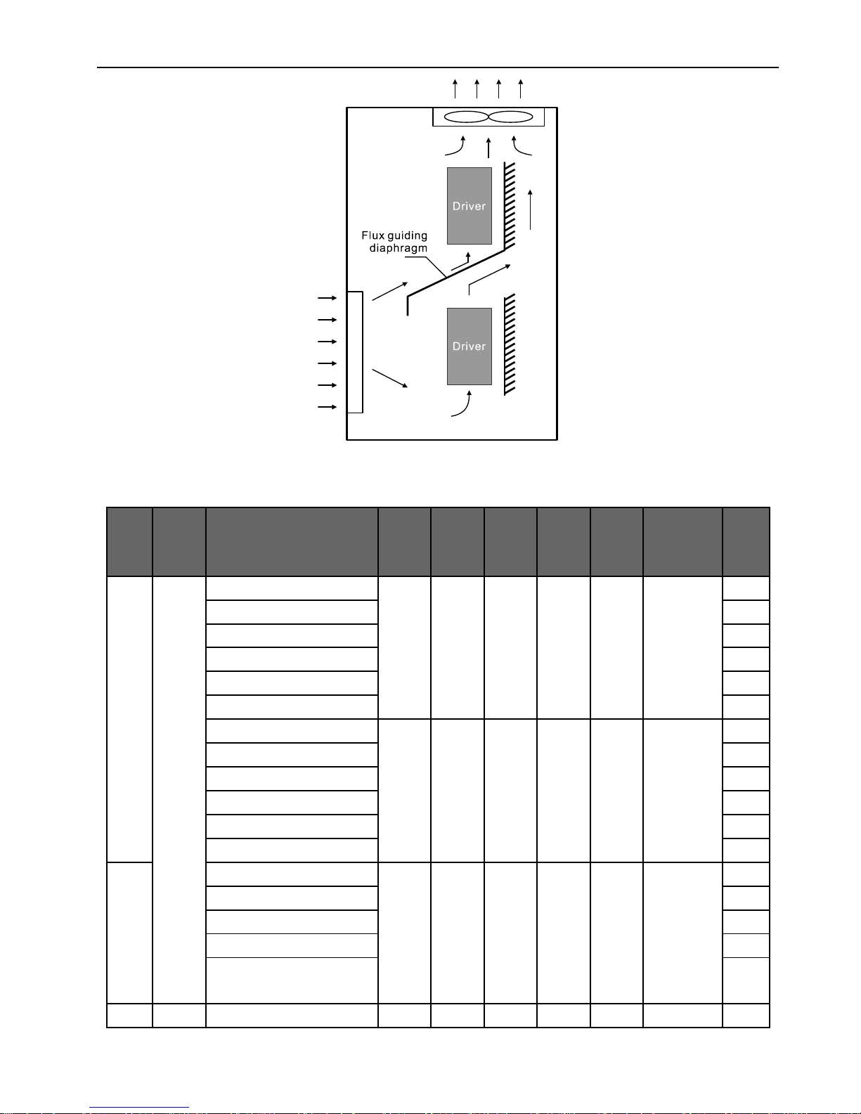
2.4.3 Installation space and heat dissipation
The inverter will create heat during operating. In order to ensure good cooling effect, it must be installed
vertically. The converter cooling duct export is available at the base for cold air entrance, to facilitate the
cooling air circulation flow, top and bottom of converter adjacent to the object must meet the minimum
requirements of the distance, as shown below: D6B/L/P series converter can be installed without clearance
side by side direction .
When several inverters are installed in one equipment or control box, horizontal arrangement is
recommended to minimize the mutual thermal influence. If the inverters have to be installed in a vertical row, a
separating board should be provided to prevent the heat from the lower inverter affecting the upper one. If the
cabinet has exhaust fans on its top, the air flow of the fans must be greater than the total out flow of all
inverters. For cabinets without exhaust fans, the top should be left open if possible, if not possible, the area of
the air vents (inlets & outlets) on the top and bottom of the cabinet must be greater than the total area of the
up & down surfaces of individual inverters, and the wind resistance at air vents should be kept as small as
possible.
If the inverter is installed on the wall of a control room, the room should have good ventilation. Installation
methods are shown as following:
2 Installation and Wiring
5
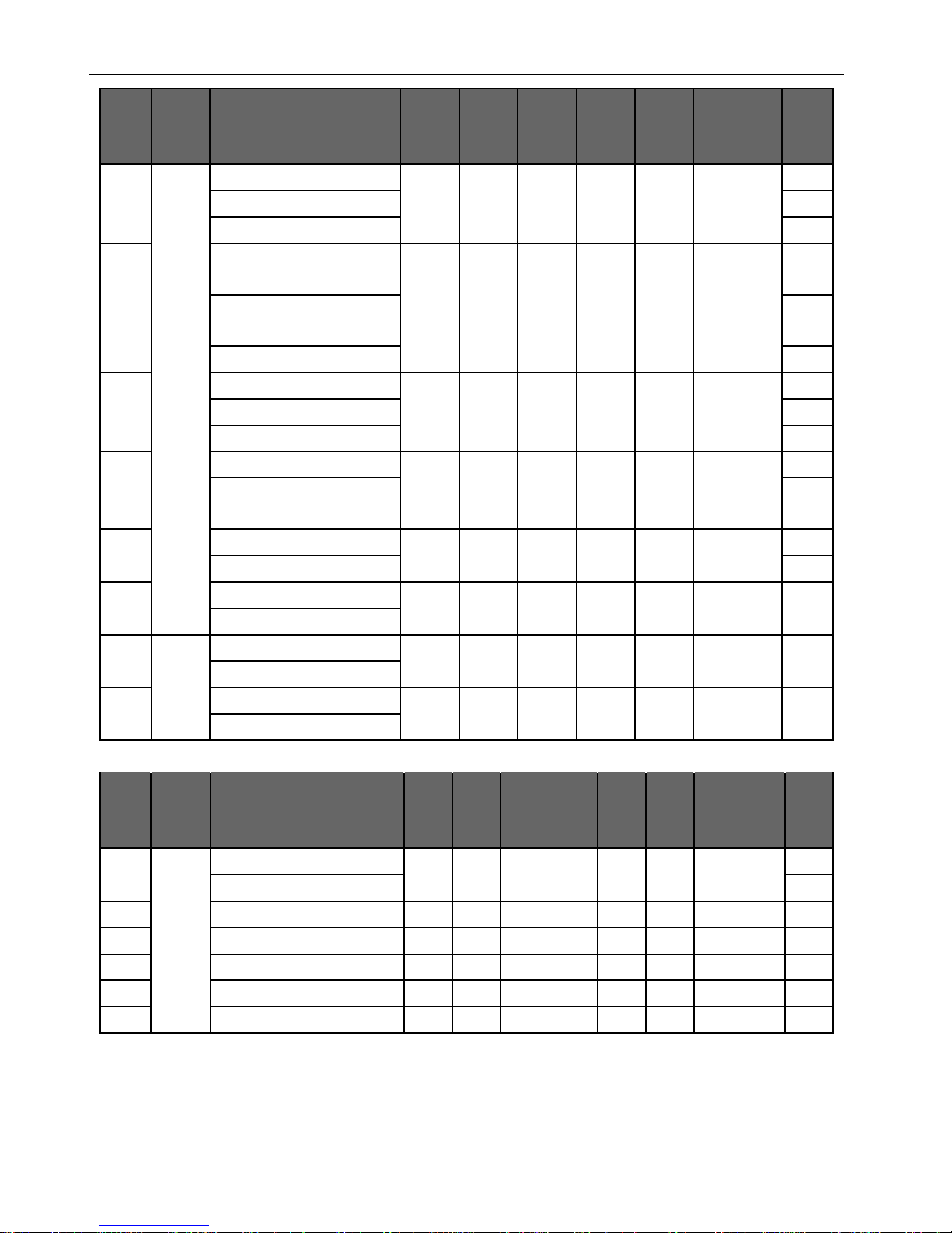
2.4.4 Appearance and installation size
Outline size and approximate weight of inverter:
Code
of box
body
Outline
Inverter type
W
(mm)
H
(mm)
D
(mm)
A
(mm)
B
(mm)
Diameter of
installation
hole(mm)
W
(kg)
F0
A
D6B-0.4S2
128
266
168
100
255
6.5
3.8
D6B-0.75S2,D6B-0.75T4
4.2
D6B-1.1S2,D6B-1.1T4
4.4
D6B-1.5T4
4.6
D6B-2.2T4
4.7
D6B-3.0T4
5.0
D6L-0.75T4
128
266
143
100
255
6.5
4.2
D6L-1.1T4
4.4
D6L-1.5T4
4.6
D6L-2.2T4
4.7
D6L-3.0T4
5
D6L-4.0T4
5.2
F1
D6B-1.5S2,D6H-1.5T4
128
276
188
100
265
6.5
4.6
D6B-2.2S2,D6H-2.2T4
4.7
D6B-3.0S2,D6H-3.0T4
5.0
D6B-4.0T4,D6L-5.5T4
5.3
D6B-5.5T4,D6H-4.0T4,
D6L-7.5T4
5.5
F2
B
D6B-4.0S2
176
280
201
140
270
6.5
5.3
2 Installation and Wiring
6
Code
of box
body
Outline
Inverter type
W
(mm)
H
(mm)
D
(mm)
A
(mm)
B
(mm)
Diameter of
installation
hole(mm)
W
(kg)
D6B-7.5T4,D6H-5.5T4
7.0
D6B-11T4,D6H-7.5T4
8.0
D6L-11T4
7.1
F3
D6B-15T4,D6H-11T4,
D6L-18.5T4
220
330
198
150
319
6.5
10
D6B-18.5T4,D6H-15T4,
D6L-22T4
11.2
D6L-15T4
9.7
F4
D6B-22T4,D6H-18.5T4
282
390
200
230
376
7
15.3
D6B-30T4,D6H-22T4,D6L-37T4
16
D6L-30T4
15.2
F5
D6B-37T4,D6H-30T4,D6L-45T4
380
410
248
280
390
11
28
D6B-45T4,D6B-55T4,
D6H-37T4,D6L-55T4,D6L-75T4
30
F6
D6B-75T4,D6L-90T4
390
600
266
300
580
11
43
D6B-90T4,D6L-110T4
46
F7
D6B-110~/160T4
465
806
329
306
780
11
*
D6L-132~/200T4
F8
C
D6B-200~/315T4
633
988
364
309
965
13
*
D6L-220~/355T4
F9
D6B-355T4,D6B-400T4
800
2093
630
*
*
*
*
D6L-400~/500T4
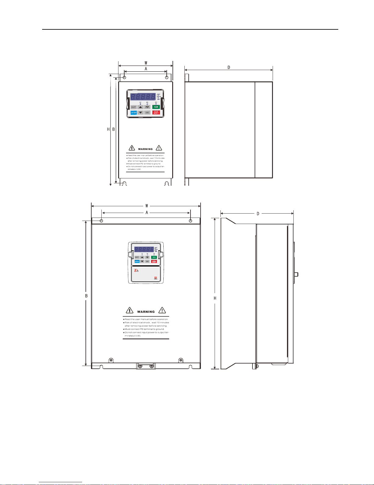
Code
of box
body
Outline
Inverter type
W
(mm)
H
(mm)
D1
(mm)
D2
(mm)
A
(mm)
B
(mm)
Diameter of
installation
hole(mm)
W
(kg)
F1
D
D6P-7.5T4,
176
280
114
103
140
270
6.5
5
D6P-11T4,
6
F2
D6P-15T4,D6P-18.5T4,
220
330
104
103
150
319
7.5
10
F2L
D6P-15T4,D6P-18.5T4,
220
380
104
80
150
369
7.5
10
F3
D6P-22T4,D6P-30T4,
282
390
104
120
230
376
7.5
14.8
F3L
D6P-22T4,D6P-30T4,
282
430
112
90.5
230
415
7.5
14.8
F4
D6P-37T4,D6P-45T4,D6P-55T4
380
410
139
129
280
390
12.0
26
2 Installation and Wiring
7
Appearance A:
Appearance B:

2 Installation and Wiring
8
Appearance C:
2 Installation and Wiring
9
Appearance D:
2.5 Removal and installation of operation keypad
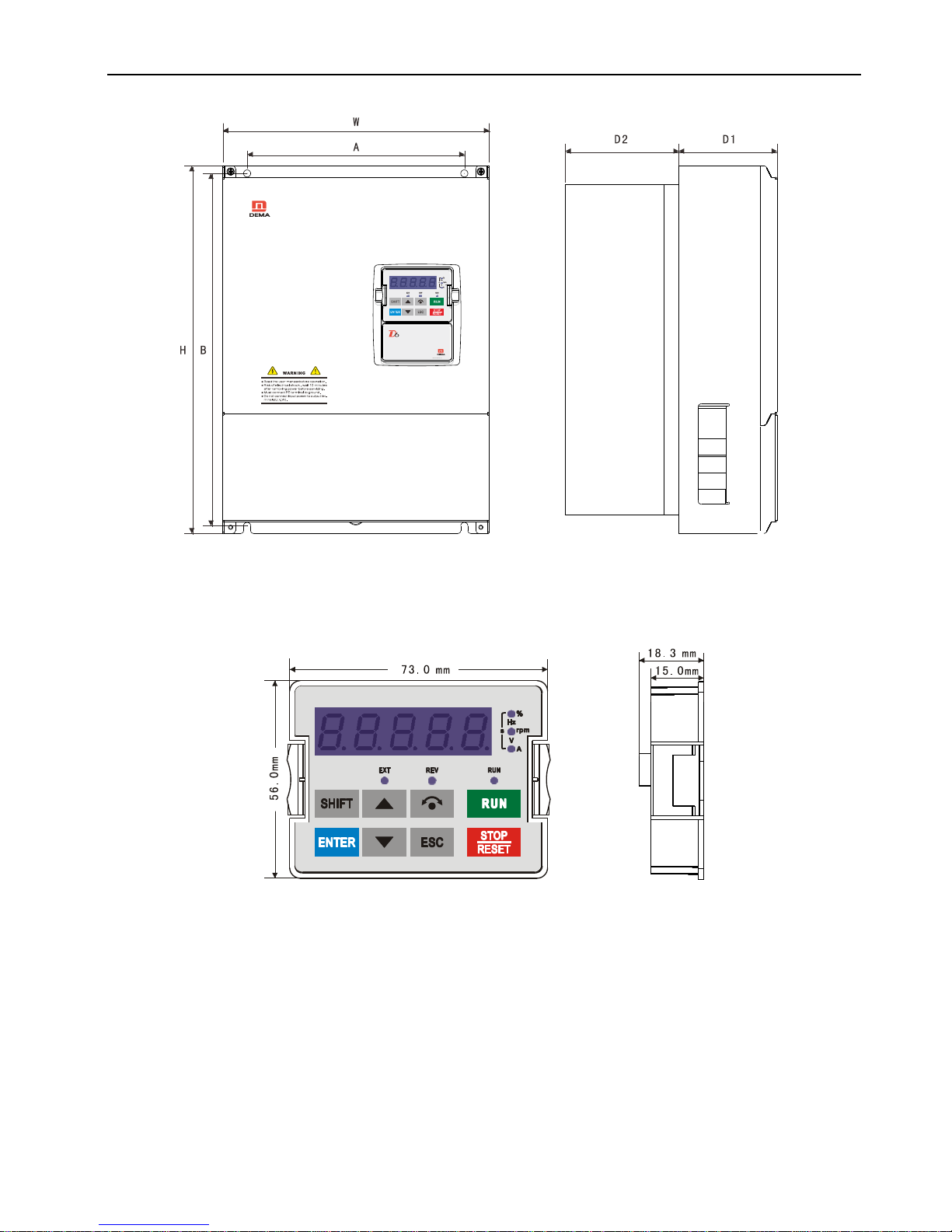
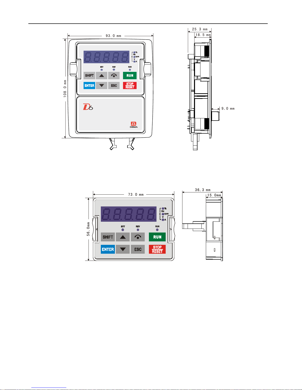
2.5.1 Appearance and size of operation keypad
2.5.2 Appearance and size of standard operation keypad installation box
The keypad box is generally used on motor which power is more than 15kW, it is also used on the installation
operation keypad of the cabinet. The installation box of the operation keypad is connected with the control
board of the inverter through extension line, the operation keypad can be purchased from the company
independently.
2 Installation and Wiring
10
2.5.3 Direct installed type operation keypad
Direct installed type operation keypad is directly installed on the keypad of the machine cabinet and not be
installed through the installation box.
Appearance size figure:
The customer can get special extension line and control panel for connection of direct installed type operation
panel on request.
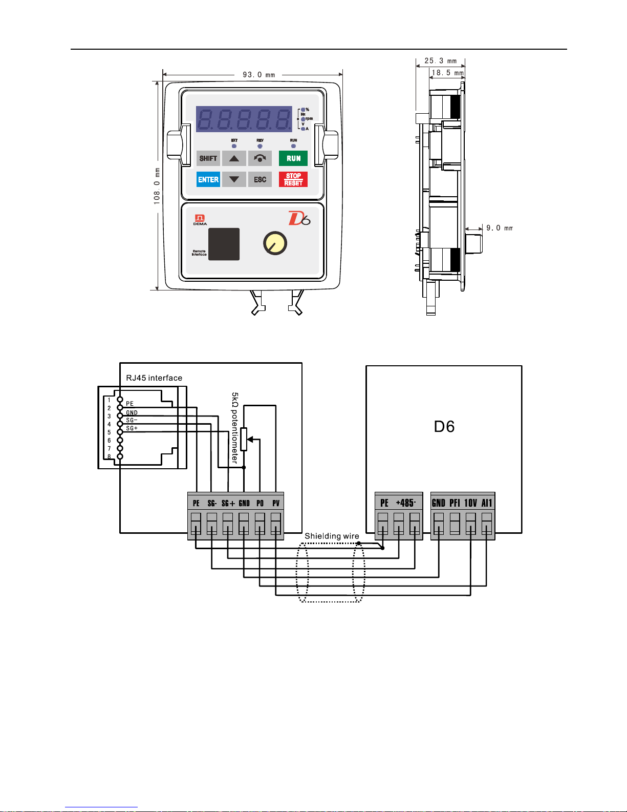
2.5.4 Keyboard installation box with potentiometer and RJ45 interface (Optional)
The customer may order keyboard installation box with potentiometer and RJ45 interface from the company
as Optional.
Appearance size figure:
2 Installation and Wiring
11
The installation box shall be connected with the control board with 6 cores cables and control board, shown as
following figure:
2.5.5 Installation and removal of operation keypad
◆ Removal
Place finger on clamp parts at left and right of the operation panel, impose force upward from the middle at
same time and pull out the operation keypad.
Installation
Place the operation panel into to groove of the installation box flat, properly press into the operation panel by
force.
2 Installation and Wiring
12
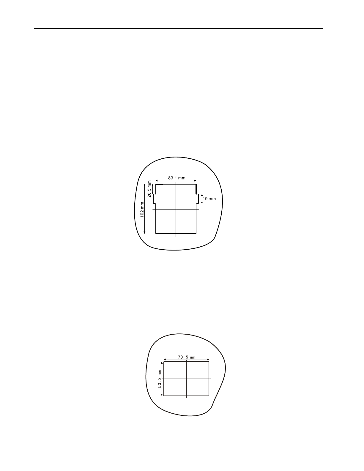
2.5.6 Installation of keypad on cabinet front cover
The keypad of D6B/L inverter can be taken off from the inverter and installed on the front cover of the cabinet,
the keypad and inverter are connected by the extension line (Manufacturer can offer specifications of 1.5
meters ~ 30m). You can choose any one of the following two installing methods.
Method 1: installed through installation box on the operation panel (the installation box can be ordered from
the company independently):
① Drill a hole in the cabinet panel. according to the following drawing;
②Install installation box of the operation panel on the panel of the machine cabinet;
③Take off the operation panel from the inverter and install in on the installation box;
④ Insert one end of the extension line into the keypad, insert the other end of the extension line into the
corresponding slot on the inverter circuit board.
Method 2: direct installation:
This method must use direct installed type operation panel and matched extension wire. The customer may
claim or order from the company, take installation of operation panel of the inverter which power class is 22kW
and below as sample:
Make an opening on the panel of the machine cabinet according to the following drawing.
Directly clamp the direct installed type operation panel on the panel of the machine cabinet.
Insert one end of the extension line into the keypad and the other end into the corresponding slot on the
inverter circuit board.

2 Installation and Wiring
13
2.6 Wiring of inverter
2.4.1 Basic wiring diagram of inverter
The user must properly connect according to following basic wiring diagrams, user can choose the control
terminal according to demand.

2 Installation and Wiring
14
2.4.2 Wiring specifications
Selection of copper-core insulation wires and incoming breaker (parameters in table are recommended
value):
Inverter model
Incoming
switch
Main circuit
Control circuit
circuit
breaker
(A)
Terminals
screws
Input
cable
(mm2)
Output
cable
(mm2)
Grounding
cables(mm2)
Terminals
screws
Control
cable
(mm2)
D6□-002S2
5
M3
2.5
1.5
2.5
M3
1
D6□-004S2
5
2.5
1.5
D6□-008S2
10
2.5
1.5
D6□-1.1S2
10
2.5
2.5
D6□-1.5S2
20
4
2.5
D6□-2.2S2
20
6
6
4
D6□-3.0S2
25
M4
6
6
D6□-4.0S2
32
10
10
D6□-0.8T4
5
M3
2.5
1.5
2.5
D6□-1.1T4
5
2.5
1.5
D6□-1.5T4
10
2.5
1.5
D6□-2.2T4
10
2.5
2.5
D6□-3.0T4
20
2.5
2.5
D6□-4.0T4
20
4
4
D6□-5.5T4
32
M4
4
4
4
D6□-7.5T4
40
6
6
D6□-11T4
63
M5
6
6
6
D6□-15T4
63
6
6
D6□-18.5T4
100
M6
10
10
D6□-22T4
100
16
16
D6□-30T4
125
M8
25
25
16
D6□-37T4
160
25
25
D6□-45T4
200
35
35
D6□-55T4
200
35
35
25
D6□-75T4
250
70
70
35
D6□-90T4
315
M10
70
70
70
D6□-110T4
400
95
95
70
D6□-132T4
400
150
150
95
D6□-160T4
630
M12
185
185
95
D6□-200T4
630
240
240
95
D6□-220T4
630
150×2
150×2
150
D6□-280T4
800
M16
150×2
150×2
150
D6□-315T4
1000
185×2
185×2
150
D6□-400T4
1200
240×2
240×2
150
Table of contents
Popular Inverter manuals by other brands


Xantrex
Xantrex FREEDOM SW 3000 owner's guide

Peak Scientific
Peak Scientific Genius 1022 user manual

Veikong
Veikong VFD700 Series Operation manual

Case IH
Case IH BC12000ER Operation manual

Black & Decker
Black & Decker BDI200 instruction manual

Hobart
Hobart 60CU24 Operation and maintenance manual with illustrated parts list