TABLE OF CONTENTS
INTRODUCTION: VERSATILE, ACCURATE, EASY-TO-USE ...........................................................1
FRONT PANEL CONTROLS ......................................................................................................................5
LED INDICATORS .......................................................................................................................................5
OUTPUT SELECTOR..................................................................................................................................... 5
OUTPUT INDICATOR LEDS.........................................................................................................................5
50 HZ /60 HZ SELECTION...........................................................................................................................5
FORMAT SELECTOR ....................................................................................................................................6
FORMAT INDICATOR LEDS........................................................................................................................6
GROUP SELECTOR ......................................................................................................................................6
GROUP INDICATOR LEDS...........................................................................................................................6
PRIOR &NEXT PATTERN SELECTOR BUTTONS ..........................................................................................7
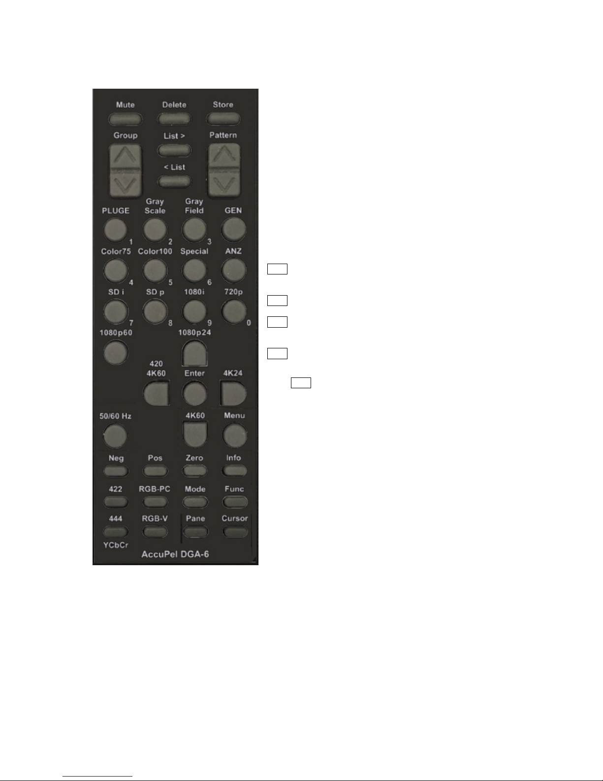
IR REMOTE CONTROL FUNCTIONS ....................................................................................................8
OUTPUT SELECTION ...................................................................................................................................8
SYNC SELECTION........................................................................................................................................8
FORMAT SELECTION ...................................................................................................................................9
PATTERN SELECTION................................................................................................................................ 10
OTHER GENERATOR IR REMOTE CONTROL FUNCTIONS ..........................................................................11
ON SCREEN DISPLAY (OSD) ..................................................................................................................12
OSD MENU SYSTEMS................................................................................................................................12
GENERATOR AND ANALYZER MENUS ......................................................................................................12
MENU NAVIGATION..................................................................................................................................13
GENERATOR PATTERN BAR...................................................................................................................... 13
GENERATOR OSD MENU...........................................................................................................................14
VIDEO ANALYZER....................................................................................................................................19
ANALYZER SOURCE &MONITOR REQUIREMENTS ...................................................................................19
ANALYZER OPERATION ............................................................................................................................19
ANALYZER IR REMOTE CONTROL FUNCTIONS.........................................................................................20
ANALYZER OSD MENU.............................................................................................................................20
ANALYZER PIXELPANE ............................................................................................................................21
ANALYZER INFOPANES ............................................................................................................................22
ANALYZER INFOFRAME TYPES ................................................................................................................24
REAR PANEL I/O........................................................................................................................................25
TEST PATTERN NOTES............................................................................................................................26
COLOR 75 GROUP .....................................................................................................................................26
COLOR 100 GROUP ...................................................................................................................................26
SPECIAL GROUP........................................................................................................................................26
PLUGE GROUP ..........................................................................................................................................27
GRAY SCALE GROUP -LOW-GS, HIGH-GS ..............................................................................................28
GRAY FIELD GROUP .................................................................................................................................28
USING THE 3D CROSSTALK PATTERN.......................................................................................................29
CHARACTERISTICS................................................................................................................................ 30
PICTURE FORMATS (59.94 &60.00 HZ BASED) ........................................................................................ 30
PICTURE FORMATS (50.00 HZ BASED)......................................................................................................31
3D MODE .................................................................................................................................................32
OUTPUT FORMATS....................................................................................................................................32
STANDARD CALIBRATION PATTERNS .......................................................................................................33
VIDEO CONNECTORS,CONTROL INTERFACES,OTHER .............................................................................33
LIMITED WARRANTY..............................................................................................................................34
APPENDIX A USB INTERFACE MANUAL ....................................................................... A-1, A-12
APPENDIX B MOTION PATTERNS MANUAL ................................................................. B-1, B-11