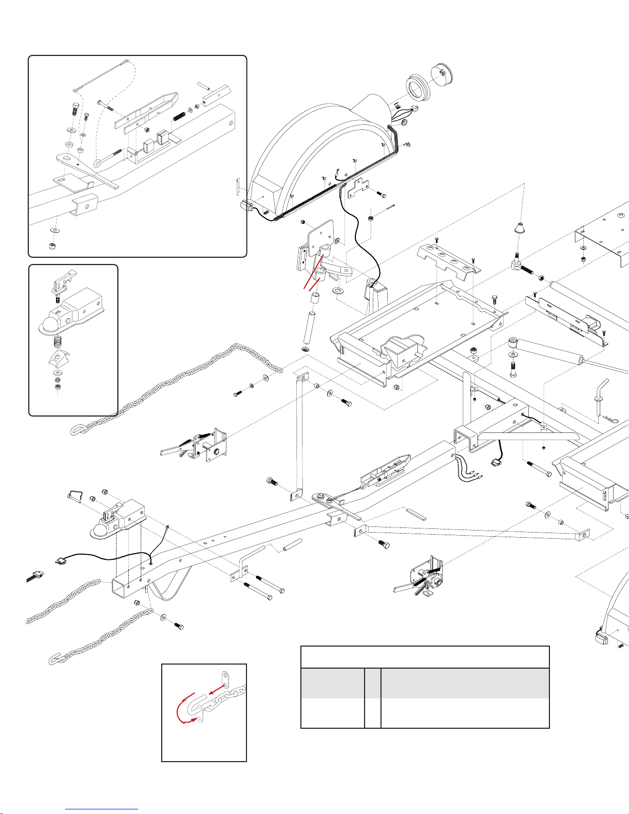
Demco KAR-KADDY KK260 User manual

Page1
OPERATORS MANUAL
KK260 (8WIDE)& KK360 (8-1/2 WIDE)
KAR-KADDY
DOING OUR BEST TO PROVIDE YOU THE BEST
DEMCO Dethmers Mfg. Co. 4010 320th St. P.O. Box 189 Boyden, IA 51234
PH: (712) 725-2311 Toll Free: 1-800-543-3626 FAX: 1-800-845-6420
www.demco-products.com
ASSEMBLY
CALIBRATION
OPERATION
REPLACEMENT PARTS
READ complete manual CAREFULLY
BEFORE attempting operation.
8-03
RD20005,Rev 3

Page2
Thank you for purchasing a Demco Kar-Kaddy. We feel you have made a wise choice and hope you
are completely satisfied with your new piece of equipment.
GENERAL INFORMATION
1. Unlessotherwisespecified,high-strength (grade5)
(3 radial-line head markings) hex head bolts are
used throughout assembly of this piece of equip-
ment.
2. Whenever the terms "LEFT" and "RIGHT" are
usedinthismanualit meansfrom a position behind
the Kar-Kaddy and facing forward.
3. When placing a parts order, refer to this manual for
proper part numbers and place order by PART NO.
and DESCRIPTION.
Introduction
tweenyou,yourdealer,orDethmersManu-
facturing Company (DEMCO).
To contact NHTSA, you may either
call the Auto Safety Hotline toll-free at
1-800-424-9393 (or 366-0129 in
Washington, D.C. area) or write to:
NHTSA,
U.S. Department of Transportation
Washington, D.C. 20590.
You can also obtain other information
about motor vehicle safety from the Hot-
line.
"Reporting Safety Defects"
If you believe that your vehicle has a
defect which could cause a crash or could
cause injury or death, you should immedi-
ately inform the National Highway Traffic
Safety Administration (NHTSA) in addition
to notifying Dethmers Manufacturing Com-
pany (DEMCO).
If NHTSA receives similar complaints,
it may open an investigation, and if it finds
that a safety defect exists in a group of
vehicles, it may order a recall and remedy
campaign. However, NHTSA cannot be-
come involved in individual problems be-
TABLE OF CONTENTS
General Information................................................................................................................ Page 2
Bolt Torque............................................................................................................................. Page 3
Safety, Maintenance, & Important Loading Instructions......................................................... Page 4
Testing Lights Before Use.................................................................................................... Pages 5
Loading Instructions ............................................................................................................ Page 5-7
Kar-Kaddy 260 and 360 Parts Breakdown and List ............................................................ Page 8-9
Kar-Kaddy 260 and 360 Parts List cont. .............................................................................. Page 10
Limited Warranty Information ............................................................................................... Page 11
DA66 Brake Actuator Parts Breakdown and List................................................................. Page 12
DA603 Brake Actuator Parts Breakdown and List............................................................... Page 13
DA91 Brake Actuator Parts Breakdown and List................................................................. Page 14
10" Self-Adjusting Brake Cluster Parts Breakdown and List ............................................... Page 15
Optional Surge Brakes Parts Breakdown and List .............................................................. Page 16
KK260 and KK360 Parts Assembly Instructions .......................................................... Pages 17-18
Wiring and Fender Assembly Instructions ........................................................................... Page 19
Kar-Kaddy Toe-In Adjustment.............................................................................................. Page 20
Wheel Jack, Deflector, & Light Bar (optional) Parts Breakdown and List ............................ Page 21
Winch, Tool Box, & Spare Tire w/Mounting Bracket (optional) Parts Breakdown and List .. Page 22
Notes.................................................................................................................................... Page 23

Page3
BOLT TORQUE
TORQUE DATA FOR STANDARD NUTS, BOLTS, AND CAPSCREWS.
Tighten all bolts to torques specified in chart unless otherwise noted. Check tightness of bolts
periodically, using bolt chart as guide. Replace hardware with same grade bolt.
NOTE: Unless otherwise specified, high-strength Grade 5 hex bolts are used throughout
assembly of equipment. Bolt Torque for Standard bolts *
GRADE 2 GRADE 5 GRADE 8
Alb-ft (N.m) lb-ft (N.m) lb-ft (N.m)
1/46 (8) 9 (12) 12 (16)
5/1610 (13) 18 (25) 25 (35)
3/820 (27) 30 (40) 45 (60)
7/1630 (40) 50 (70) 80 (110)
1/245 (60) 75 (100) 115 (155)
9/1670 (95) 115 (155) 165 (220)
5/895 (130) 150 (200) 225 (300)
3/4165 (225) 290 (390) 400 (540)
7/8170 (230) 420 (570) 650 (880)
1225 (300) 630 (850) 970 (1310)
Torque figures indicated are valid for
non-greased or non-oiled threads and
heads unless otherwise specfied.
Therefore, do not grease or oil bolts or
capscrews unless otherwise specified
in this manual. When using locking
elements, increase torque values
by 5%.
* GRADE or CLASS value for bolts
and capscrews are identified by their
head markings.
Torque Specifica-
tions
CLASS 8.8 CLASS 9.8 CLASS 10.9
Alb-ft (N.m) lb-ft (N.m) lb-ft (N.m)
6 9 (13) 10 (14) 13 (17)
7 15 (21) 18 (24) 21 (29)
8 23 (31) 25 (34) 31 (42)
10 45 (61) 50 (68) 61 (83)
12 78 (106) 88 (118) 106 (144)
14 125 (169) 140 (189) 170 (230)
16 194 (263) 216 (293) 263 (357)
18 268 (363) -- -- 364 (493)
20 378 (513) -- -- 515 (689)
22 516 (699) -- -- 702 (952)
24 654 (886) -- -- 890 (1206)
Bolt Torque for Metric bolts *
GRADE-2 GRADE-5 GRADE-8
8.8 10.9
9.8
CLASS 8.8 CLASS 9.8 CLASS 10.9

Page4
SAFETY
Safety is of utmost importance at all times. There are
several items that must be checked each time before
using and while using the Kar Kaddy.
Make sure all bolts are properly tightened and those
requiring a set torque are up to specifications:
Tie Rod Castle Nut - 75 ft./lbs.
Lug Nuts - 75 to 80 ft./lbs.
Check Lug Nut tension after the first 5 miles and
periodically thereafter.
The ball hitch must latch securely around the ball and
thesafetylockpinorlevermustbeinpositiontolockthe
hitch on the ball.
RECOMMENDED BALL HEIGHT: 18 inches to the top
of the ball on the towing vehicle.
Hookthetowedvehiclesafetychainstotheframeofthe
vehicle directly above the area where the chain is
mounted on the Kar Kaddy. Leave some slack in the
chain to allow suspension movement.
Check to make sure that all lights are in proper working
order.
Examine the winches and straps, making sure they are
in good conditon.
Be certain the safety lock pins are locking the strap
winches.
Retightenstrapsoverthetiresafterthefirst 5 miles and
every 50 miles thereafter. Ensure that they are tight.
The KK260 tires must be inflated to the recommended
50 PSI.
The KK260SB, KK360 and KK360SB tires must be
inflated to the recommended 50 PSI.
Thestrapontheoptional tongue winchmustbeingood
condition and should be stored neatly on winch when
not in use.
NOTE: The winch strap must not be left connected to
the towed vehicle after it is loaded and strapped down.
Make sure the optional light bar is fastened securely at
the rear of the towed vehicle.
Thewirestotheoptionallightbarshouldberunalongthe
car and fastened so as not to damage the finish of the
towed vehicle.
NOTE: Thisunitcannotbebackedup,whenloadedor
with the steering lock pin removed.
AllvehiclesmountedontheKarKaddymustbemounted
with the front of the vehicle facing forward.
Rear Wheel Drive: Disconnect the towed vehicle
driveshaft for rear wheel drive vehicles with automatic
transmission.
For manual transmission: Consult your vehicle owners
manual for towing suitability with the drive shaft con-
nected. MAINTENANCE
Periodically check all bolts and nuts to insure proper
tension or torque.
Grease the king pin and tie rod end grease zerks every
2500 miles.
Anoccasionaldrop ofoilmayberequiredonthemoving
parts of the tie down winches.
Alightfilmofoilshouldperiodicallybeappliedtosteering
stabilizer arm to prevent rust.
NOTE: Proper toe-in is 1/32". This is preset at the
factory.
Theoperatorshouldperiodicallyhavethetoe-inchecked
and adjusted if needed at a qualified alignment shop.
Improper toe-in can result in irregular tire wear.
IMPORTANT LOADING INSTRUCTION
Check your wheel tie-down straps.
Your Kar Kaddy is equipped with custom made
wheel tie-down straps of a standard size that will fit
most tires, however if your tires are too large or too
small you will want to exchange these new straps
for the proper size straps.
1. Tire too large - This is very obvious the strap
will not basket over the tire properly, call us,
wewillprovide at NO Chargeonan exchange
basis, the proper size strap. You must return
your new unused straps and provide us with
the Make and Model car and the tire size.
2. Tire too small - This is not as obvious, the
basket will fit down over the tire very well, the
problems cannot be readily seen. You must
tighten the straps down solid and then check
on the inside of the tire and be sure the strap,
when tightened does not come in contact with
anymetalthatmaycausewearorcuttingsuch
asstrutmounts. Ifthereiscontact,youneeda
smaller strap, call us, we will provide on a NO
Charge,exchangebasis,thepropersizestrap.
You must return your new unused straps and
provide us with the Make and Model car and
tire size.
Thank you for Purchasing Products.
WARNING:
FAILURE TO FOLLOW THESE INSTRUCTIONS CAN RESULT IN LOSS OF TOWING VEHICLE CONTROL,
SEPERATION OF THE TOW DOLLY FROM THE TOWING VEHICLE, SEPERATION OF THE TOWED VEHICLE FROM
THE TOW DOLLY, CAUSING SEVERE PERSONAL INJURY, DEATH, OR PROPERTY DAMAGE.
!
!

Page5
TESTING LIGHTS BEFORE USE
1. CheckthattheWHITE(ground)wireofthewiringharness
is connected to the Kar Kaddy frame and the WHITE
(ground) wire is connected to the frame of the towing
vehicle.
2. With headlights in "ON" position, the tail lights, the light
clusterbar,thelicenseplatelight,andtheclearancelights
should be lighted.
3. Start engine and have someone depress brake pedal.
Brake lights of tow dolly and towing vehicle should come
"on" and "off" simultaneously with each application.
4. Turn left turn signal on. Left turn light of Kar Kaddy and
towing vehicle should flash simultaneously. Should the
turnsignallights ofthetrailer functionoppositeto thoseof
thetowingvehicle,itisprobablethattheYELLOW(Driver
side) and GREEN (Passenger side) wires have been
reversed. Checkthe plugconnectionunder thetongue of
theKarKaddytomakesurewirecolorsare notcrossedat
thatpoint. If plug connectionis incorrect,correct problem
by reversing yellow and green wire connection on the
towing vehicle.
Step 1. Secure ball coupler to 2" (5,000 lb. capacity) towing
vehicle ball only. Make sure that the hitch and the hitch ball
are in good condition and not rusted, loose or stripped.
Recommended ball height is 18" to the top of the ball.
Make sure hitch is locked down and secured with safety clip.
Criss-cross safety chains under tongue and secure to towing
vehicle frame.
LOADING INSTRUCTIONS
Refer to load limits on inside of front cover.
Step 3. Loosen wing nut on back of license plate holder, turn
thecliponthefronttoahorizontalpositionandputlicenseinthe
"down"position. Turn theclip backsoitrestsagainst theback
of the light bar to hold the license down and tighten wing nut.
(License must be "UP" with the tow dolly empty).
Step 2. Remove black locking pin BEFORE loading vehicle
onto the Kar Kaddy. The removal of the locking pin allows
"AutoSteer"tooperate. Whentowingthedollyempty,thispin
must be in place.
IMPORTANT: Tire tread width or body width of towed
vehicle must not exceed:
KK260 - 70" max. (outside to outside),
42" min. (inside to inside),
72" max. (body width).
KK360 - 76" max. (outside to outside),
42" min. (inside to inside),
78" max. (body width).
Step 4. Before loading (and unloading) towed vehicle make
sureplatformandtowedvehicleareinstraightalignment. Tow
dollymustbecompletelyandproperlyhookeduptothetowing
vehicle. Towing vehicle must be larger and at least 1000
lbs. heavier than the tow dolly and towed vehicle com-
bined.

Page6
Step 5. Grasp bed release handle on tongue and pull
toward coupler. This releases the tilt bed to permit loading.
Step 7. Drivevehicleontotheplatform- front forward-until
tires touch the wheel stops at the front of each side of the
platformand theplatform tiltsto aflat position. Makesure the
cariscentered on the platform.Towed vehicle tires mustfit in
wheel troughs without overhanging sides. Engage towed
vehicle parking brake. Shift loaded car into "park" and lock
steering wheel with front tires in a straight position. If the car
does not have a locking steering column the steering wheel
must be tied securely with front tires in a straight position.
Rear Wheel Drive: Disconnect towed vehicle driveshaft for
rear wheel drive vehicles with automatic transmission.
For manual transmission: Consult your vehicle owners
manual for towing suitability with the drive shaft connected.
Step 8. Place one tie-down strap over each tire and secure
hooksto rodslocated atthe rearof eachwheel platform. The
short side of the hook must face the rear of the Kar Kaddy.
Step 9. Besuretie-downwinchiscenteredwiththetirebefore
tightening straps.
Step 6. With someone safely guiding you, slowly drive ve-
hicleontoplatformFRONTFORWARD.(Anyvehiclemounted
on tow dolly must be mounted with front of the vehicle facing
forward.) Drivethecarforwarduntilthetirestouchtheramps.
Make sure the tire is aligned to ascend onto the ramps.

Page7
Examinewinches and strapsto make surethey are in
goodcondition.
Check wheel nuts every trip.
Tiresmustbeinflatedtorecommendedpressurebytire
manufacturer.
Be certain the safety lock pins lock the strap winches.
Retightenthestrapsoverthetiresafterthefirst5miles
of travel. Check straps every 50 miles therafter to
ensure they are tight and not rubbing or fraying.
Step 10. Threadtie-downstrapthroughtheslottedtubeonthe
tie-down winch. Pull approx. 6" of strap through this slot.
Begintighteningstrapmakingsurethetailbecomesenclosed
bythestrap coming overthe tire. Tighten thestrapsensuring
thatthestrapfedthroughtheslotbindsbetweentheshaftand
the strap being wound onto the winch shaft. While tightening
straps, pull cross strap forward to ensure even tightening.
NOTE: Be sure to tighten straps until each tire starts to
flatten against tire stop. After each strap is tight, insert a
safety pin in each winch. Disengage towed vehicle parking
brake.
Strapsmustberetightenedafterfirst5milesoftravel. Check
strapsevery 50 milesthereafterto ensure theyaretight and
not rubbing or fraying.
Step 14. TopulltheKarKaddyempty,make sure"Auto-
Steer" LOCKING PIN IS IN PLACE and towing vehicle
safetychainsareupandhooked. Tie-downwinchhandles
should be left in a down postion (horizontal) position with
safety pins in place when towing loaded or empty. DO NOT
ATTEMPT TO PULL KAR KADDY WITH WHEEL PLAT-
FORM IN LOADING (tilted) POSITION.
DAMAGE PREVENTION
Check your vehicle manual or registration for vehicle weight.
Towingvehiclemust be largerand at least 1,000lbs. heavier
than the towed vehicle and tow dolly combined.
Donotpackgoodsincarthatisbeingtowed. Overloadingthe
Kar Kaddy or exceeding the width limit may result in damage
to both car and Kar Kaddy.
REAR WHEEL DRIVE PRECAUTIONS
Disconnect towed vehicle driveshaft for rear wheel drive
vehicles with automatic transmission. Simply placing trans-
mission in neutral is not sufficient to prevent damage to
transmisssion.
Formanualtransmission: Consultyourvehicleownersmanual
for towing suitability with the drive shaft connected.
ALL VEHICLES MOUNTED ON THE KAR KADDY MUST BE
WITH THE FRONT OF THE VEHICLE FACING FORWARD.
Step 12. Hook the towed vehicle safety chains to frame of
vehicledirectly abovethe areawherethe chainsare mounted
on the Kar Kaddy. Leave some slack in the chains to allow
suspension movement of the towed vehicle.
Step 11. Make sure the tie-down strap is the correct size for
the auto tire. See page 11 of this instruction for proper fit and
exchange instructions.
Step 13. TO UNLOAD towed vehicle. Make sure that plat-
formandvehiclearestraight. Reinstalldriveshaft. Ensurethat
towedvehicleparkingbrakeisfullyengaged,thenunhookthe
towedvehiclesafetychains,and releasethetie-downstraps.
NOTE: Tiedownstrapsmustbe"quick-released"bygrasping
ratchet pawl (A) and ratchet handle (B) simultaneously and
pushingdownsharply. Thisprocesswillpermiteasyremoval
of strap from winch.Swing the wheel platform locking latch
handle forward, towards the coupler. This will allow the
platform to tilt as you slowly drive off. Make sure the winch
ratchet handles are horizontal. Replace the "Auto Steer"
locking pin (for towing empty).
AB
SAFETY

Page8
RightFender
1
2
45
45
34
35 43
37
38
42
48
49
49
40
41
39
44
46 47
53
86 46
47
52
52
10
100
54
54
55
55
56
56
57
58
35
58
51
42
36
66 82
25
81
80
78
51
89
90
90
103
104
33 109
110
111
112
113
114
108
107
106
105
100
99
98
*69
*69 *69
*69 72
75
63
62 65
75
46
88
61
60
KK260 (8'wide) and KK360 (8-1/2' wide) PARTS BREAKDOWN
50
5217
Coupler Repair Kit
not included
for
Fulton
5000 lb.
coupler
83
KIT #5511
TILT-BED LATCH
ASSEMBLY
128
121
122
123 124
125
126
127 129
120
87
118 116
117
46
55
55
42
119
59
DECALS
RD21002 1 Instruction Decal
RD21003 - 5 ft. Gold Striping (for fenders)
RD21001 4 Kar Kaddy Decal (brown)
DA21005 - Check Wheel Nuts & 50 Psi. CRange BSW
(KK360, KK260SB, KK360SB)
ZA21003 1 VIN
DECAL
NO. QTY. DESCRIPTION
Part# 07426
Hook Retainer
Replacement Only
71

Page9
KK6LBAS
License Plate Mount
and Light Cluster
(not available)
25
25
24
26
26
27
29
30
30
31
31
32
84
27
27
78
79 77
75
76
51 74
55
42
85
73
130
*70
*70
*70
*70
104
109
115
103
64
68
67
93
94
95
102
LeftFender
Left Winch Shown
151413
10
9
4
12
19 20
20
22
16
18
17
23
21
76
12
11
8
3
5
1. 5432 1 Left Ratchet Winch Assembly (Plated)
2. 5433 1 Right Ratchet Winch Assembly (Plated)
3. 03569-95 1 Ratchet Frame
4. 03570-95 1 Left Spool Tube
-03571-95 1 Right Spool Tube
5. 03577 1 Heavy Duty External Snap Ring
6. 03574-95 1 Ratchet Handle
7. 03668 1 18 Ga. Shim Washer
8. 03575-95 1 Left Ratchet Gear
-03576-95 1 Right Ratchet Gear
9. 03666 1 5/16" x 1-1/4" Roll Pin
10. 02243 1 Black Vinyl Hand Grip
11. 05450 1 Winch Pawl
12. 01864 2 Winch Pawl Spring SS
13. 05449 1 Winch Pawl Bushing SS
14. 00059 1 3/8" Flatwasher
15. 05444 1 3/8"-16 UNC x 3/4" Hex Bolt w/epoxy Gr.5
16. 03572-95 1 Left Ratchet Pawl Arm
-03573-95 1 Right Ratchet Pawl Arm
17. 03578 1 5/16"-18 UNC x 1/2" Shoulder Screw
18. 01998 1 5/16" Flatwasher SS
19. 02002 1 1/4" Flatwasher SS
20. 02772 2 1/4"-20 UNC Nylon Locknut
21. 04055 1 1/4"-20 UNC x 1" Hex Hd. Bolt Gr.5
22. 00214 1 1/4" Flatwasher
23. 05337 1 Lock Pin w/Cable
- 5192 License Plate Light and Light Cluster
24. 04505-25 1 License Plate and Light Cluster Bracket
25. 04176 4 1/4"-20UNC x 3/4" Carriage Bolt
26. 02519 2 1/4"-20UNC x 1/2" Slotted Truss Head Bolt
27. 02163 1 Square License Plate Light w/washer and nut
-02164 - Clear License Plate Light LENS ONLY
REF. PART
NO. NO. QTY. DESCRIPTION
28
91 92
5
3
87

Page10
REF. PART
NO. NO. QTY. DESCRIPTION
29. 02580-95 1 License Plate Clip
30. 02770 2 1/4-20UNC Nylon Insert Wing Nut
31. 01077 2 1/4"-20UNC Serrated Locknut
32. 04513 1 Light Cluster
10. 02243 2 Black Vinyl Hand Grip
33. 01883 11 Electrical Wire Splicer
34. 01881 1 Trunk Connector
35. 04785 1 Front Half Trailer Wiring Harness
36. 04786 1 Rear Half Trailer Wiring Harness
37. 01855 1 Safety Lock Pin
38. 04496 1 5000 lb. Ball Coupler (lever lock)
39. 02288-95 1 Bolt on Handle
-04017-95 1 Bolt on Handle (used with brakes)
40. 01338 2 1/2"-13UNC x 4-1/2" Hex Head Bolt (gr.5)
-01975 2 1/2"-13UNC x 5" Hex Hd. Bolt (gr.5) (used w/ brakes)
41. 02189 1 1/2" I.D. Rubber Handle Grip
42. 02178 13 1/2"-13UNC Nylon Insert Locknut
43. 01863 1 5/8" Grommet for wiring harness
44. 02771 2 7/16"-14UNC Nylon Insert Locknut
45. 01853 2 24" Transport Safety Chain w/ Hook
-02383 2 36î Transport Chain w/ Hook (used w/ brakes)
46. 00059 9 3/8" Flat Washer
47. 01898 4 7/16"-14UNC x 1-1/4" Hex Head Bolt (gr.5)
48. 07077-26 1 Kar Kaddy Tongue
49. 03503 2
5/8"-11 UNC x 1-1/4" Epoxied Hex Hd Bolt (gr.5)
50. 02434 1 5/8"-13UNC x 4-1/2" Hex Head Bolt (gr.5)
51. 02587 3 5/8"-13UNC Nylon Insert Locknut
52. 02747-25 2 Bracing Strut
53. 02383 2 36" Safety Chain
54. 02579-95 2 Pivot Bushing
55. 00085 12 1/2" Flatwasher
56. 01254 2 1/2"-13UNC x 1-1/2" Hex Head Bolt (gr.5)
57. 04815 2 Grommet
58. 02772 8 1/4"-20UNC Nylon Insert Locknut
59. 04642 2 Grease Zerk
60. 01731 4 1-1/4" Dust Cap
61. 01734 2 1" dia. x 6-1/2" lg. King Pin
62. 01732 4 1"I.D. x 1-1/4"O.D. x 1-1/2"lg. Bushing (brnz)
63. 04165-26 1 Right Wheel Carrier
64. 04166-26 1 Left Wheel Carrier
-04642 4 1/4"-28UNF Grease Zerk
65. 05587 2 1" I.D.x 14 GA Narrow Rim Machine Washer
66. 07075-26 1 KK260 Main Frame (8' wide)
-07076-26 1 KK360 Main Frame (8-1/2' wide)
-09528-26 1 KK260SB Main Frame (8' wide)
-09529-26 1 KK360SB Main Frame (8-1/2' wide)
67. 04369 2 Hub and Spindle (115mm B.C.)
-02917 - Replacement 12mm x 1.5 Stud Bolt
68. 02210 8 7/16"-20UNF x 1-1/4" grade 8 Epoxied Bolt
*69. 5179 1 Right Tie Rod End w\Right Hand Threads
*70. 5178 1 Left Side Tie Rod End with Left Hand Threads
71. 07426 4 Rubber Hook Retainer
72. 01905 1 9/16"-18UNF Jam Nut w/Right Hand Threads
73. 01904 1 9/16"-18UNF Jam Nut w/Left Hand Threads
74. 01869-26 1 Tie Rod (KK260 - 8' wide)
-04771-26 1 Tie Rod (KK360 - 8-1/2" wide)
75. 02592 16 3/8"-16UNC Nylon Insert Locknut
76. 01871-26 1 Tie Rod Shock and Stop Mount Back-up Plate
77. 01870-26 1 Tie Rod Shock and Stop Mounting Clamp
78. 02696 2 5/8"-11UNC x 2-3/4" lg. Hex Head Bolt (gr.5)
79. 00907 6 3/8"-16UNC x 1" Hex Head Bolt (gr.5)
80. 00477 1 5/8" Flatwasher
81. 01729-26 1 Steering Stabilizer Cylinder
REF. PART
NO. NO. QTY. DESCRIPTION 82. 01718-95 1 Locking Pin
-02189 1 Black Handle Grip
83. 00182 1 Small Hair Pin
84. 03528 2 Tie Down Strap w/J-Hook
85. 04503-25 2 Tilt Bed Ramp (KK260 - 8' wide)
-04772-25 2 Tilt Bed Ramp (KK360 - 8-1/2' wide)
86. 00078 2 7/16" Lockwasher
87. 00967 8 1/2"-13UNC x 1-1/4" lg. Hex Head Bolt (gr.5)
88. 04167 6 7/16"-20UNF x 1" lg. Hex Head Bolt (gr.8)
89. 04171-25 2 Rear Tire Stop (KK260 - 8' wide)
-04773-25 2 Rear tire Stop (KK360 - 8-1/2' wide)
90. 00523 4 3/8"-16UNC x 1-1/4" lg. Hex Head Bolt (gr.5)
91. 00789 2 3/8"-16UNC x 3/8" lg. Hex Socket Set Screw
92. 01930 2 3/8"-16UNC x 1/4" lg. Hex Socket Set Screw
93. 04941 2
P195/75R14 "B" Range BSW Radial Tire (KK260)
-04826 2 ST205/75R14 "C"Range BSW Radial Tire
(KK360,KK260SB,KK360SB)
94. 04367 2 Rim (6 x 14) (serial # 19001 & later)
95. 02933 10 Chrome Lug Nut
-5333 1 LH Fender Assembly (qtyís below are for 1 fender)
-5334 1 RH Fender Assembly (qtyís below are for 1 fender)
28. 00214 3 1/4" Flatwasher
97. 05356 1 Left Fender
98. 05355 1 Right Fender
- 4 Stainless Steel Ground Strap
99. 04508 1 Amber Fender Reflective Decal
100. 04498 1 Front Fender Light with lead wire
101. 01769 1 Kar Kaddy Mud Flap
102. 05338 2 1/4"-20UNC x 3/4" lg. Brown Sltd Truss Bolt
103. 05446 1 4-1/2" Enclosed Round Tail Light
104. 05447 1 Rubber Grommet for 05446 Light
105. 04424-95 1 Fender Back-up Plate
106. 02316 1 White Ground Wire
107. 00914 3 3/8"-16UNC x 1-1/2" lg. Hex Head Bolt (gr.5)
108. 04499 3 3/8" I.D. External Tooth Lockwasher
109. 02313 1 3-Way Plug Pigtail (tail light)
110. 04944 1 5/8" Grommet (thin wall)
111. 05443 1 Cable Hanger - wire harness
112. 02298 1 22-1/2" Wire Protector Loom
113. 04425 4 Tinnerman Fender Clamp
114. 04515 1 17-1/2" Wire Protector Loom
115. 04804 1 Red Fender Reflective Decal
116. 05449 1 Spacer Bushing - Stainless Steel
117. 05444 1 3/8"-16 UNC x 3/4" Epoxied Hex Bolt (Gr 5)
118. 03382-95 1 Latch Handle Pivot Bushing
119. 03574-95 1 Latch Handle
120. 03434 1 5/16"-18 UNC x 5-1/4" Eye Bolt
121. 04221 1 5/16"-18 UNC x 2-1/2 Hex Head Bolt (Gr 5)
122. 02802 1 5/16-18 UNC Nylon Insert Locknut
123. 03381-95 1 Latch Catch
124. 00007 1 5/16"-18 UNC Hex Nut
125. 03379-95 1 Latch Block
126. 03435 1 Roll Pin (5/16" x 2-1/4")
127. 03499 1 Latch Spring - Stainless Steel
128. 03433 1 Latch Cable
129. 00004 1 5/16" Flatwasher
130. 04168 6 7/16"-20UNF Nylon Insert Locknut
-CMO8021 12 oz. Buckskin Touch-up Paint (Aerosol)
-IC8633 12 oz. Brown Touch-up Paint (Aarosol)
* Indicatesthiskitincludesappropri-
ate tie rod end (left or right hand
threads), grease zerk, rubber cup,
cotter pin and castle nut.

Page11
1. Extent and Duration of this Warranty:
Your Demco Kar Kaddy is warranted to be free from defects in
materials and workmanship under normal use and service for a
period of one year after date of purchase by the original (first)
retail owner, or until it is resold or transferred by the original
owner. New Departure Hyatt Hubs used on the KK260 and
KK360 are warranted for a period of three years after the date of
purchase by the original (first) retail owner or until itís resold or
transferred by the original owner. Tires and lights are not
included in this warranty.
Tires are warranted by the manufacturer against defects in
materials and workmanship, but not against road hazards.
Any part of the Demco Kar Kaddy, except tires and lights, found,
in the judgement of the manufacturer to be defective in materials
orworkmanship willberepairedorreplaced atthemanufacturerís
option without charge for parts or labor to the original owner.
2. Manufacturer and Warrantor of Tow Dolly:
Dethmers Manufacturing Co.
4010 320th Street
P.O. Box 189
Boyden, IA 51234
(712) 725-2311
The manufacturer and warrantor of the tires has his name
permanently molded into the tires. Tire warranty questions and
claims can be taken directly to an authorized dealer of the tire
manufacturer.
3. Repair or Replacement Procedure:
If your Demco Kar Kaddy develops a defect (except for tires or
lights) during the warranty period, promptly notify Dethmers
Manufacturing Co. customer service department. Until such
noticeisreceived, Warrantor will not beresponsibleforanyrepair
or replacement.
Upon receipt of notice from you, Warrantor will have a choice of
options in replacing any part it determines to be defective:
a) Warrantor may require you at your own expense to deliver
or ship the part to its factory or authorized dealer. Any
defective part will be repaired or replaced and returned to
you free of charge. Any part returned to Warrantor and
found not to be defective will be returned to you freight
collect with an explanation.
b) Warrantor may elect to ship a new part to its dealer to be
exchanged free of charge for the defective part returned
by you to the dealer.
c) Warrantor may elect to ship or deliver a replacement part
to your address.
Warranty claims on tires should be presented to a local autho-
rized dealer of the tire manufacturer. Provide proof of purchase
when making a tire warranty claim.
4. Limitations on Warranty Coverage:
Coverage under this warranty will be effective only when a copy
oftheoriginalinvoice,showingthedateandlocationofpurchase,
accompanies any claim for warranty.
Warrantorhasnoliabilitywhatsoeverandthiswarrantyisnullandvoid
if any Demco Kar Kaddy has been misassembled or subjected to
neglect,negligence,misuse,accidentoroperatedinanywaycontrary
totheoperatingandmaintenanceinstructionsasspecifiedintheDemco
OwnerísManualforthatmodeltowdolly.
This warranty does not cover any tow dolly that has been altered
or modified so as to affect the tow dollyís operation, performance
or durability, or that has been modified to change the intended
use of the tow dolly.
In addition, the warranty does not extend to repairs made
necessary by normal use of parts, accessories or other equip-
ment which in the judgment of Warrantor, are either incompat-
ible with the Demco Kar Kaddy, or affect its operation, perfor-
mance or durability.
This warranty does not cover:
1) normal wear and tear
2) road film or gravel damage to paint
3) paint
4) rust damage
5) AnyDemco KarKaddythat hasbeenloaded inexcessof the
load capacity stated on the tow dolly identification label.
Warrantorhasapolicyof continuous product improvement. We
reserve the right to change or improve the design of any Demco
Kar Kaddy model, including but not limited to state of the art
changes, without assuming any obligation to modify any tow
dolly previously manufactured.
Warrantorassumesnoresponsibilitytotheownerforlossofuse
of the tow dolly, loss of time, inconvenience or other damage
consequential or otherwise, including, but not limited to ex-
pense for gasoline, expense of transporting the tow dolly to the
dealer and expense of returning the tow dolly, mechanicís
travel time, telephone or telegram charges, road service/towing
charges, rental of another tow dolly during the time warranty
repairs are being performed, travel, lodging, loss or damage to
personal property or loss of revenue or earnings.
5. Limitations of Implied Warranties:
All implied warranties, if any, expire and terminate upon expi-
ration of this warranty. Some states do not allow limitation on
how long an implied warranty lasts, so this limitation may not
apply to you.
6. Limitation of Consequential Damages:
Warrantorís responsibility under this warranty extends solely to
repair or replacement of your Demco Kar Kaddy and its com-
ponent parts.
Warrantor does not assume responsibility for, nor shall it be
liable for, any special, incidental or consequential damages.
Some states do not allow the exclusion or limitation on inciden-
tal or consequential damages, so the above exclusion or
limitation may not apply to you.
7. Use of Vehicle Identification Number (VIN):
The VIN is a 17 digit number located in the lower left corner of
the tow dolly identification label. The label is located on the left
side of the tow dolly frame. Be sure to include the VIN number
in all communications with Warrantor or its dealers concerning
the warranty.
8. Purchaserís Rights:
This warranty gives you specific legal rights, and you may also
have other rights which vary from
DEMCO PRODUCTS - KAR KADDY
ORIGINAL PURCHASERíS LIMITED WARRANTY

Page12
Model DA66 ACTUATOR PARTS BREAKDOWN
-8606701 1DA66 Brake Actuator complete (incl. ref. 1-25)
-5400 -Lever Replacement Kit (incl. items w/*)
-5398 -Master Cylinder Repair Kit w/ gasket
-5495 -Coupler Repair Kit
ACTUATOR PARTS LIST
Please order replacement parts by PART NO. and DESCRIPTION.
REF. PART
NO. NO. QTY. DESCRIPTION
2
24
6
6
22
23
2
21
1
11
12
7
7
5
10
10
2
2
3
18
19 19
13
15
16
20 20
14
89
4
17
1. 07599-95 1 6000# 2" Ball Coupler
2. SB23278 4 Roller
3. 05957-95 1 Front Roller Spacer
4. 02166 1 3/8"-16UNC x 2-3/4" Hex Head Bolt (gr.5)
5. 07176 1 3/8" Stover Lock Nut
6. 05684 2 1/2"-13UNC x 4-1/2" Hex Head Bolt (gr.5)
7. 02178 2 1/2"-13UNC Nylon Insert Lock Nut
8. 05959 1 Push Rod Assembly
9. 05692 1 Damper/ Shock
10. 05958-95 2 Rear Roller Spacer
11. *05951 1 Emergency Lever
12. 05955-95 1 Front Cover
13. *SB24700 1 2' Cable with S-Hooks
14. SB10555 2 Replacement S-Hook ONLY
15. 05960 2 5/16"-18UNC x 1/2" Self-Tapping Screw
16. 05424 2 5/16" External Tooth Lock Washer
17. *05693-95 1 Emergency Lever Spring
18. 03876 1 Master Cylinder Cap w/ diaphragm & O-ring
19. 01076 4 1/4-20UNC x 3/4" Hex Head Bolt
20. 00057 4 1/4" Lock Washer
21. 03564-95 1 Outer Case
22. 05681 1 Replacement Master Cyl. Gasket ONLY
23. 05680 1 Master Cylinder with gasket 05681 X
24. SB12098 1 1/8" pipe - 3/6" inverted Flare Fitting
25. 05966-95 1 Back Cover
25
5495
Coupler Repair Kit
for
6000lb.
coupler
5398 Master Cylinder Repair Kit
(gasket included)

Page13
5695 - Emergency Lock Cam Replacement Kit
20. ----- 1 7/16î-14UNC x 1 1/4î Hex Head Bolt (Gr. 5)
21. ----- 1 7/16î-14UNC Lock Nut (Center Punch)
22. ----- 1 Emergency Catch Cam (black oxide finish)
23. ----- 1 Pushrod Assembly (includes cable)
5696 -Coupler Repair Kit (2î lever lock)
5398 -Master Cylinder Repair Kit w/ gasket
DA603BRAKEACTUATORPARTSBREAKDOWN
5398 Master Cylinder Repair Kit (drum)
(gasket included)
2
4
20
7
8
21
9
16
10
11
13 12
22
14
15
23
3
1
Please order replacement parts by PART NO. and DESCRIPTION.
6
1. 00057 4 1/4î Lock Washer
2. 00062 4 1/4î-20 UNC Hex Nut
3. 00179 1 3/8î-16 UNC Lock Nut (Center Punch)
4. 00618 4 1/4"-20UNC x 2" Hex Head Bolt (Gr.5)
5. SB12098 1 .018 Connector Orifice (Drum Brakes)
6. 02207 1 3/8î-16UNC x 3î Hex Head Bolt (Gr. 5)
7. 03876 1 3 Tab Fill Cap w/ Diaphram & O-Ring
8. 09153 1 Master Cylinder Gasket (incl. in 10616 & 11190)
9. 10616 1 Composite Master Cylinder (drum)
10. 11367-95 1 Coupler/Inner Slider (plated)
10a. 5698 - Coupler/Inner Slider w/ Lever Lock Assy.
11. 11368 2 Top Plastic Slider
12. 11369 2 Bottom Plastic Slider
13. 11371-95 2 Shock Spacer (plated)
14. 11389-95 1 Rear Shock Pin (plated)
15. 11390-95 1 Outer Case (plated)
16. 11401 2 External Snap Ring
17. SB12426 1 Damper
18. 05687 1 Protective Boot (incl. in 10616 & 5398)
-8606301 -Plated Actuator f/ drum brakes
ACTUATORPARTSLIST
REF.
NO. PART NO. QTY. DESCRIPTION
12
11
17
5696 Coupler Repair Kit
(2î lever lock)
**Components not sold separately**
Item #23
includes cable
Item #10 is not
included in 5696
18
18
10a
5
2
REPLACEMENTKITS
(componentsnotsoldseparately)
5695 Emergency Lock Cam
Replacement Kit
20
21
22
23
Components not
sold separately

Page14
MODEL DA91 ACTUATOR PARTS BREAKDOWN
5398 Master Cylinder Repair Kit
(gasket included)
2î Lever Lock Coupler
RATEDAT6000#
notincluded
REF.
NO. PART NO. QTY. DESCRIPTION
Model 91 ACTUATOR PARTS LIST
1. 09417 1 6000# 2" Lever Lock Coupler (zinc plated)
2. 01896 3 1/2"-13UNC x 4" Hex Head Bolt (gr.5)
3. 02178 3 1/2"-13UNC Nylon Insert Lock Nut
4. 05426 1 Front Shock Pin (drop tube actuators)
5. 11079-95 1 Drop Tube Actuator Slider (plated)
6. SB12426 1 Damper/ Shock
7. 11164-95 1 3 Bolt Mount Outer Case (plated)
8. 05424 2 5/16" External Tooth Lock Washer
9. 02363 2 5/32" x 1 1/4 Cotter Pin(Qty 3 w/drop tube)
**10. 05408 1 3/32" Cable with hooks
11. SB10555 - Replacement S-Hooks ONLY
**12. 05693-95 1 Emergency Lever Spring (plated)
13. 05961 2 5/16"-18UNC x 5/8" Hex Head Bolt (gr.5)
14. 00618 4 1/4-20UNC x 2" Hex Head Bolt (gr.5)
15. 00057 4 1/4" Lock Washer
**16. 05951 1 Emergency Lever Assembly
17. 03876 1 Master Cylinder Cap w/ Diaphragm & O-ring
-05849 1 O-Ring Only (not shown)
18. 05977 1 Push Rod Assembly
19. 00062 4 1/4-20 UNC Hex Nut
20. 09153 - Plastic Master Cyl. Gasket ONLY
21. 10616 1 Master Cylinder
-11190 - Master Cylinder
22. SB12098 1 .018 Connector Orifice (Drum Brakes)
23. 03866-95 1 Lever Guide (plated)
24. 05687 1 Master Cylinder Protective Boot
25. 05986-95 1 Connecting Pin (plated)
26. 10965 1 Upper Slider
27. 10966 1 Lower Slider
28. 10967 2 Side Spacers
-5401 - Lever Replacement Kit (incl. items w/**)
-5650 - Master Cyl. Replacement Kit (drum)
-5495 - Coupler Repair Kit
23
**16
22
20
21
19
17
24
13
14
11
9
**10
6
4
3
2
7
5
15
1
8
Please order replacement parts by PART NO. and DESCRIPTION
2
8
9
14
15
18
19
25
26
27
28
28
**12
9
BLEEDING THE SYSTEM
The first requirement for safe, sure hydraulic braking is the use
ofqualitybrakefluid. UseonlyDOT-3orDOT-4brakefluidfrom
a sealed container.
If pressure bleeding equipment is available, follow the
manufacturerís instruction in bleeding the system.
If system must be bled manually, proceed as follows: Fill
master cylinder with fluid. Install bleeder hose on first wheel
cylinder to be bled.
Have loose end of hose submerged in brake fluid in glass
container to observe bubbling.
By loosening the bleeder screw located in the wheel cylinder
one turn, the system is open to the atmosphere through the
passage drilled in the screw. Pump actuator with long steady
strokes. The bleeding operation is completed when bubbles
no longer rise to the surface of the fluid. Be sure to close
bleeder screw securely.
Repeat bleeding operation at each wheel cylinder. During the
bleeding process, replenish the brake fluid, so the level does
not fall below the 1/2 full level in the master cylinder reservoir.
After bleeding is complete, make sure master cylinder reser-
voir is filled and filler cap is securely in place.
After the bleeding operation has been completed, apply pres-
suretothe systemandcheckthe whole brakesystemfor leaks.
5495
Coupler Repair Kit

Page15
44
557
16 22
1
16
3
8
6
10
10
18
17
13
REF. PART
NO. NO. QTY. DESCRIPTION
BRAKE CLUSTER PARTS LIST
11
12
9
15
17
14
17
18
17
-SB24429 -Left Hand Cluster (shown above)
-SB24428 -Right Hand Cluster
1. SB23871 1 Back Plate Assembly - (NDH Hub Mounting)
2. SB9254 2 Cover Plate - Adjusting Hole
3. SB10954 1 Brake Shoe Kit (includes 2 Primary & 2 Secondary)
4. 04305 2 5/16"-18UNC-Gr5 x 1/2" Hex Hd Bolt
5. 05424 2 5/16" External Tooth Washer
6. SB9776 1 Wheel Cylinder Assembly - Right
-SB9777 1 Wheel Cylinder Assembly - Left
7. 05431 1 Bleeder - replacement
8. SB9783 1 Push Rod
9. SB24047 1 Adjusting Screw Assembly - "R" (for LEFT cluster)
-SB24048 1 Adjusting Screw Assembly - "L" (for RIGHT cluster)
10. SB10958 2 Spring - Shoe
11. SB10961-95 1 Shoe Guide
12. SB23937 1 Cable
13. SB23936 1 Cable Guide
14. SB23724 1 Spring - Adjusting Screw
15. 05415-95 1 Lever - Right
-05414-95 1 Lever - Left
16. SB10959 2 Pin - Shoe Hold Down
17. SB9789 4 Cup Shoe Hold Down
18. 05983 2 Spring - Shoe Hold Down
19. 03380 1 Spring
19
Please order replacement parts by PART NO. and DESCRIPTION.
Brake shoe kit can be ordered for one complete axle only.
-SB15845 1Wheel Cylinder Repair Kit
(includes spring, cup and boot)
-SB40929 210" Brake Drum
3
10" SELF-ADJUSTING BRAKE CLUSTER and DRUM PARTS BREAKDOWN

Page16
OPTIONAL SURGE BRAKES (KK260SB and KK360SB) PARTS BREAKDOWN
ModelDA603
BrakeActuator 1
23
4
5
56
7
8
2
9
Please order replacement parts by PART NO. and DESCRIPTION.
SURGE BRAKES PARTS LIST
1. SB587 1 87" Brake Line
2. 01863 2 RubberGommet
3. 02746 1 54" Protective Hose
4. SB7H67 1 7"BrakeHose(rubber)
5. SB536 2 36" Brake Line (KK260SB)
5. SB540 2 40" Brake Line (KK360SB)
6. SB7764 2 RubberBrakeLineClip
7.
SB10H136
2 10"BrakeHose(rubber)
8. 02210 8 7/16"-20UNF x 1-1/4" Epoxied Bolt (gr.8)
9. 04174 4 12mmRetainerWasher(2perdrum)
10. 00496 2 MachineWasher
11. 02549 4 RubberProtector
12. SB7785 1 3/16Brake Line Tee
13. SB24429 - Left Brake Cluster
-- SB24428 - Right Brake Cluster
14. SB15545 - 10îBrakeDrum
REF. PART
NO. NO. QTY. DESCRIPTION
10
11
12
14
13
BLEEDING THE SYSTEM
The first requirement for safe, sure hydraulic braking is the use
ofqualitybrakefluid. UseonlyDOT-3orDOT-4brakefluidfrom
a sealed container.
If pressure bleeding equipment is available, follow the
manufacturerís instruction in bleeding the system.
If system must be bled manually, proceed as follows: Fill
master cylinder with fluid. Install bleeder hose on first wheel
cylinder to be bled.
Have loose end of hose submerged in brake fluid in glass
container to observe bubbling.
By loosening the bleeder screw located in the wheel cylinder
one turn, the system is open to the atmosphere through the
passage drilled in the screw. Pump actuator with long steady
strokes. The bleeding operation is completed when bubbles
no longer rise to the surface of the fluid. Be sure to close
bleeder screw securely.
Repeat bleeding operation at each wheel cylinder. During the
bleeding process, replenish the brake fluid, so the level does
not fall below the 1/2 full level in the master cylinder reservoir.
After bleeding is complete, make sure master cylinder reser-
voir is filled and filler cap is securely in place.
After the bleeding operation has been completed, apply pres-
suretothe systemandcheckthe whole brakesystemfor leaks.

Page17
KK260 AND KK360
ASSEMBLY INSTRUCTIONS
1. Place the main frame on blocks or some other sturdy
support so that the frame rests approximately 8" - 10" off
theground. Attachthetiltbed ramps(#1)as shownusing
four 1/2" x 1-1/4" grade 5 bolts (#4), flat washer (#5) and
lock nuts (#6), two on each side of each ramp, and then
three7/16"x1"grade8bolts(#2)andlocknuts(#3)onthe
top of each ramp. Torque 7/16" bolts to 80 ft. lbs. and
torque 1/2" bolts to 75 ft. lbs.
2. Attachrear tire stop (#7)as shown usingtwo 3/8" x1-1/4"
grade 5 bolts (#8), flat washers (#9) and lock nuts (#10).
These 3/8" x 1-1/4" bolts will also go through the tilt bed
ramps. Torque 3/8" x 1-1/4" bolts to 35 ft. lbs.
3. Hold tongue up to
front of trailer and
locate the three
bullet connectors
extending out the
back of the tongue
andplugintothecon-
nector protruding from under the main frame channel. Do
not cross colors when making this connection. See
drawing above. Make sure the the pigtail for the license
plate bracket is out.
4. Mount the tongue (#11) to the front of the Kar Kaddy
mainframeusinga5/8"x4-1/2"grade5bolt(#12)andlock
nut(#13)(torqueto 50ft.lbs). Donottorqueover50ft.lbs.
or bed will not tilt.
5. Mount the latch handle (#14) to the mounting plate using
the 1/2" x 1-1/4" grade 5 bolt (#15), two 1/2" flatwashers
(#16),bushing(#17),and1/2"locknut(#18).Putstainless
steel bushing (#19) into latch cable (#20) and secure to
handle using 3/8" x 3/4" grade 5 bolt (#21) and 5/16"
flatwasher(#22).Adjustlatchsocableissnugbyloosening
bolt and nut and sliding handle forward or back.
24" Chain
36" Chain
Yellow/Brown
Wires
Green/Brown
Wires
LatchHandle
Installation
Connector
1
1
2
3
4
5
6
7
8
11
12
13
14
15
16
17
16
18
1920
21
22
23
23
9
10
24
26
2625 24
25 27
28
28
293031
32
33
34
35
36
37
38
39
40 40 42
43
41
6. Laythebracingstruts(#23)outalongthetowdollytongue
withthe back end (theend with thelarger hole init)of the
bracingstruttowardthemainframe. Looselybolttheback
of each bracing strut to the trailer frame as shown using
1/2" x 1-1/2" grade 5 bolt (#24), flatwasher (#25), pivot
bushing(#26)andlocknut(#27). Holdupthefrontend(the
end with the smaller hole) of each bracing strut to the
tongueandsecurewithtwo5/8"x1-1/4"epoxiedhex head
bolts (#28). Torque the 1/2" x 1-1/2" bolt with the pivot
bushingto75ft.lbs. Torquethetwo5/8"x1-1/4"epoxied
hex head bolts to 100 ft. lbs.
7. Removethe7/16"x1-1/4"bolt(#29),flatwasher(#30),and
lockwasher(#31)fromthefrontofeachwheelplatformtire
stop. Slide the tie-down winches into the channel at the
frontofthewheelplatformsasshown. Theratchethandles
aretotheoutsideofeachwinchandratchetspringsareto
thetop. Attach twotowedvehicle safetychains (#32,36"
long). Secure one chain to each wheel platform tire stop
and replace flat washer, lock washer and 7/16" x 1-1/4"
bolt.
8. Attach each hub and spindle assembly (#33) as shown
using four 7/16" x 1-1/4" grade 8 epoxied bolts (#34).
(Torque to 80 ft. lbs.)
9. Securethe hitchcoupler (#35)and thelifthandle(#36)to
the front end of the tongue (#11) with two 1/2" x 4-1/2"
grade5bolts(#37)andlocknuts(#38). Thewhiteground
wire is attached under the head of the rear bolt attaching
thehitch coupler. (Itis veryimportant thata goodground
ismade). Torque the locknuts to 75-80 ft.lbs. Tapthe
rubbergrip(#39)ontothehandlewitharubberhammeror
awooden mallet.
10. Attachthetwo24"longtransportsafetychains(#40)tothe
two holes located in the tongue rest using two 7/16" x 1-
1/4" grade 5 bolts (#41), flat washers (#42) and lock nuts
(#43). Torque bolts to 50 ft. lbs.
Pigtail
Brown/Green
Brown/Yellow
Yellow
Green
Brown

Page18
11. DONOTMOVETHETIERODLOCKINGCLAMPFROM
ITS FACTORY PRESET POSITION.
GREASE TIE ROD ENDS BEFORE USING.
NOTE: Tie rods are factory set and should not be
readjusted.
12. Boltonthesteeringstabilizercylinder(#1)asshownusing
a 5/8" x 2-3/4" bolt (#2) coming up from the bottom,
througha 5/8"flat washer(#3), throughcylinder endand
intothreadedearontheKarKaddymainframe. Snugbolt
up,thentightenputting3/16"squeezeontherubberofthe
cylinder end. The final gap between the flat washer and
the threaded ear is 1-1/4". Lock in place with a 5/8" lock
nut (#4). Extend cylinder and attach the other end of the
cylinder to the tie rod locking clamp using a 5/8" x 2-3/4"
boltandlocknut. Alignlockingclampandtowdollyframe
ear,slideinblackhandlelockingpin(#5)andsecurewith
hair pin (#6).
The "auto steer" feature is locked.
NOTE: If installed properly there should be a 1-1/4" gap
betweentheflatwasherandthethreadedearasshownin
Figure A.
NOTE: Alight filmof oil shouldbe appliedto retractable
shaft of steering stabilizer cylinder to prevent rust from
forming. If Kar Kaddy sets idle for extended periods of
time, turn wheels of tow dolly so that the shaft is fully
retracted to prevent rust.
Figure A
13. Mountthelicenseplatebracket(#7)totheframeasshown
using 1/4" x 3/4" carriage bolts (#8) and lock nuts (#9).
Plugpigtailintolicenseplatelight. Installlicenseplateand
license plate clip (#29) as shown on the top of page 17.
14. Bolt the fenders (#10) on as shown using 3/8" x 1-1/2"
grade 5 bolts (#11), back-up plates (#12) and lock nuts
(#13)ineachfender. Mountthefenderwiththelightpocket
totherear. The3/8"I.D.externalstarwasher(#14)mounts
betweenfenderinnerframeandmainframemountingplate
toensureagoodground. Attachthewhitegroundwire(the
endwiththeeyelooponit)underthecentertopbolthead.
The tie rod and locking clamp is
shown unattached to the Kar
Kaddy for illustration purposes
only. The tie rod is shipped as-
sembled for you.
Tie Rod Locking Clamp
Grease Zerk
White
Ground Wire
Grease Zerk
1-1/4"
1
2
3
4
5
6
7
8
9
9
8
2
4
10
11
12
13
14

Page19
WIRING & FENDER
ASSEMBLY INSTRUCTIONS
NOTE: It is advantageous to wire the fender lights
prior to attaching the wheels.
1. Cutoffstrippedendsofthewiringharness,cutoffstripped
ends of the front clearance light, and cut off the stripped
endofthewhitegroundwire. Theyellow/brownwiresmust
be run to the left tail light pocket. The green/brown wires
mustbe run totheright tail lightpocket. Starting at either
fender, pull the loom downward from the center of the
fenderandpushthegreen/brown(oryellow/brown)wires
upward through the loom until it comes out by the light
pocket. Pushthewhitegroundwire throughtheslit inthe
topoftheloominthefendertroughtowardthelightpocket.
2. Push the brown clearance light wire through the loom on
the front of the fender until it comes out the loom in the
centerofthefender,thenpushthebrownwirethroughthe
slitin thetopof theback loomand towardthelight pocket
until it comes out the loom. Mount the amber clearance
light to the front of the fender using the stainless steel
grounding strap (attached to the steel frame inside the
fender)SEEBELOW,thena1/4"flatwasherandlocknut.
Makesurethewire runsthroughtherecessinthebackof
the light so it doesn't get pinched when tightening the
mountingnut.
3. When wiring the pigtail into the tow dolly harness at the
fenderpocket,thewireendsshouldNOTbestripped. Use
the wire connectors to make all contacts. Lay the wire in
theconnector, pinchsecurely withapliers,closethe wire
connector.
Pushthehollowloopedendofthefenderwireloomhanger
into the small hole under the fender pocket on the side of
the fender. Leave the holder open.
Make sure all four wires are coming out the fender wire
loom. Slidetherubberfendergrommetoverthewiresand
up close to the wire loom. Splice the brown clearance
fenderlightandtowdollybrownwiretogether. Makesure
the connector is far enough from the loom to allow you to
pushtheconnectorintotheholeinthefenderpocketlater.
4. Pull the black and white wire from the pigtail through the
hole in the fender pocket outward. Splice the white wire
to the white wire coming out the loom. Splice the black
wire to the brown wire. Splice the green (or yellow) wire
totheredwireofthepigtail. Maketheconnectionsonthe
outside of the fender pocket, then push the connectors
andwiresbackintothefenderpocket.Pushthegrommet
into the fender with the wire loom close to the grommet.
Wraptheloomhangertiearoundthewireloomandinsert
the peg into fender.
White
Triple Wire Plug
fromLight
Black Red
White Wire
Connector
Yellowor
Green
Yellow/Brownor
Green/Brown
WIRINGDIAGRAMFORTHE
TOWDOLLYFENDER
5. Push the round rubber light seal into the light pocket. Be
surethelipissecuredinthelighthousing. Plugthepigtail
into the fender light. Push the round light into the rubber
seal until it snaps in firmly. Wire the other fender in the
samemanner.
6. Mountthemudflapstotheinsidebackofthefenderusing
two 1/4" x 3/4" brown colored truss head bolts with flat
washersandlocknuts. MakesuretheKarKaddylogoon
the flap faces the rear.
7. Attach the wheels to the main frame. Use the supplied
lug nuts (#4) and torque to 75 - 80 ft. lbs.
WIRING OF THE TOWING VEHICLE
Connect wiring to towing vehicle, keeping in mind the color
codeindicated below.
1. Make certain towing vehicle lights are "OFF".
2. ConnectYELLOW wiretoleftturnsignalandstopwirein
theleftrearoftowingvehiclewiththewiresplicer(01883)
supplied.
3. ConnectGREENwiretotherightturnsignalandstopwire.
4. Connect BROWN wire to tail light wire.
5. VERYIMPORTANT-connectWHITEwiretoframebody
oftowingvehicle. Thisisthecommonground,andaclean
metal - to - metal contact must be made.
CAUTION: Manyflashersforvehicleturnsignalswillnot
carry the additional load of Kar Kaddy turn signals. If
normal operation does not occur when connected to the
Kar Kaddy, a heavy duty replacement flasher may be
obtained through auto parts outlets.
WHITE Ground
BROWN Tail Lights, License Plate Lights,
Light Cluster Bar & Clearance Lights
YELLOW Left Turn and Stop
GREEN Right Turn and Stop
COLORCODEFORWIRINGHARNESS
Inside of fender with grounding
strapattached.
Brown
Brown
Jumper
BrownJumper
toFront
Clearance
Light
WhiteGround Wire to
Fender

Page20
12"
12"
C
L
BACK MEASUREMENT
FRONT MEASUREMENT
(1/32" to 1/16" less than back measurement)
18"
Ground
1.
Put a mark on each side of the locking clamp on the
tie rod.
2. Loosenthelockingnutsoneachendofthetierodandthen
the six bolts on the tie rod locking clamp.
3. Turn the tie rod whichever direction is needed until you
have a front measurement of 1/32" to 1/16" less than the
backmeasurement.
4. Hold the tie rod and tighten the locknuts on each end.
5. Measureagaintomakesurethetoe-inmeasurementhas
not moved.
6. Tighten the locking clamp bolts while holding clamp
between the marks you previously put on the tie rod.
7. Reassemble the rest of the Kar Kaddy unit.
Have the tongue in a "hooked-upposition with the ball
coupler 18" off the ground. Jack up the axle just enough to
allowyoutotakethewheels offandputblocksundertheaxle.
Take the wheels off.
Findtwo24"longbars, thesecouldbealevel,asquareor
a straight piece of iron bar. Clamp one bar tight to the face of
each hub with 12" extending forward and backward of the
centerofthespindle. Thebarsmustbeparalleltotheplatform
the car sits on. Measure across the back end of the bars and
then across the front end. The front measurement should be
1/32" to 1/16" less than the back measurement. If the unit
needstobeadjusted,thismustbedonebyadjustingthetierod.
TOE-IN ADJUSTMENT
MEASURING THE TOE-IN
KAR-KADDY TOE-IN ADJUSTMENT
LOCKING
CLAMP
This manual suits for next models
1
Table of contents
Other Demco Utility Vehicle manuals