DENAGO eXC 2 User manual

QUICKSTART
GUIDE
eXC 2

With over 100 years of collective experience, our team loves to share
with you what we learned from riding, working in bike shops
and working in the bike industry.
We are looking forward to you joining us for a ride.

THANK YOU and welcome to the Denago team.
We value and appreciate you and your choice.
If there is anything you need, please reach out
and let us know how we can help.
Email: [email protected]
Call Us: 877-755-2453 (BIKE)

ALWAYS WEAR A HELMET
Please make sure you read, understand and follow the instructions
in the quickstart guide as eBikes are new to most riders.
For more information, please visit:
denago.zendesk.com

EXC MODEL 2 5 | DENAGO
EXC MODEL 2
6 | DENAGO QUICKSTART GUIDE
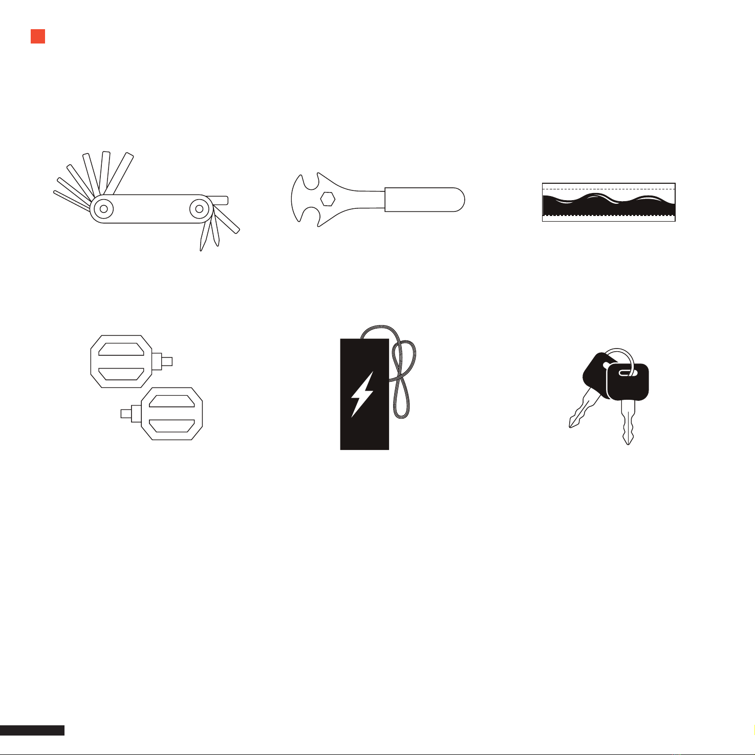
WHAT’S IN THE BOX
The following accessories are included with your 90% pre-assembled Denago bike.
Pedals Battery Charger Battery Keys
Multi Tool Pedal / Wheel Wrench Bicycle grease packet
YOUR DENAGO BIKE IS 90% ASSEMBLED
The quickstart guide will assist you in completing the assembly.
By following the directions, you will be able to get outside and start
riding your new Denago eBike in less than 30 minutes.
If you are not comfortable or confi dent, please take your
bike to your local shop and ask for assistance.

GETTING STARTED

EXC MODEL 2 9 | DENAGO
Unpack and Unwrap your eBike

10 | DENAGO QUICKSTART GUIDE
LAY OUT THE PARTS AND TOOLS
We’d like to make your assembly process a bit easier.
So we made a Parts & Tools layout inside the box.
Please lay Parts & Tools into each area.
Tool Set Front Wheel
& Parts
Pedals Other Stu

ASSEMBLY STEPS
1. HANDLEBAR
2. SADDLE
3. FRONT WHEEL & BRAKE
4. PEDALS
5. DISPLAY
6. ADJUSTMENTS

12 | DENAGO QUICKSTART GUIDE
HANDLEBAR COMPONENTS HAVE BEEN PRE-ASSEMBLED
Please tighten and secure all bolts
1. Disassemble the package, unscrew
the bolt and remove the cover, bolt and
paper tube, leaving all spacers in place.
2. Put the handlebar riser into the front
fork steerer tube according to the gure.
3. Attach the cover and bolt to the stem,
straighten the handlebars, and tighten
the top bolt rst and then tighten bolts
on both sides of the stem with
a 4mm hex tool.
4. Install the display on the right side
of the stem with a 2.5mm hex tool after
removing the xing screws
5. Finally, lock the display with the
2.5mm hex tool.
You will use the 4mm allen key on the multi tool for these steps.
ASSEMBLY | HANDLEBAR
6. Tighten the front reector with a
Phillips screw-driver
EXC MODEL 2 13 | DENAGO
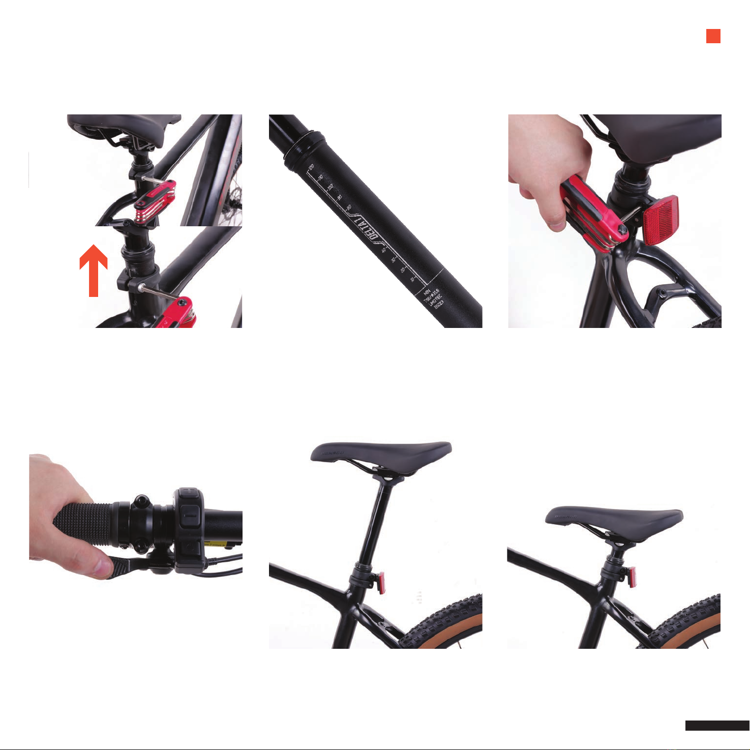
SEAT | ASSEMBLY
1. Loosen the seat clamp with a 6mm
hex tool. To pull the seatpost up, push or
feed the dropper remote cable into the
downtube and up the seat tube.
2. Tighten the seatpost clamp.
Set the rear reector to an appropriate
height and then tighten with
a Philips screwdriver.
THE SEAT WAS PRE-ASSEMBLED
THE USAGE OF DROPPER POST
1. Without weight on the saddle,
press the remote to raise the seat post.
2. To lower the seatpost, press the
remote while applying bodyweight
on the saddle.
NOTE: DO NOT EXCEED THE MINIMUM INSERTION
MARK WHEN SETTING THE SADDLE HEIGHT

14 | DENAGO QUICKSTART GUIDE
ASSEMBLY | FRONT WHEEL & BRAKE YOUR BIKE HAS A THRU-AXLE MECHANISM
1. Remove the shaft and the ller block
from the front disc brake caliper with
a 6mm hex tool.
2. Position the front wheel so that it is
centered between the front fork legs
and the shaft is in the front fork rack.
3. Align the disc brake of the front wheel
set with the disc brake seat to mount the
disc on the front fork.
4. Finally, insert the shaft into place on
the right side of the front fork and lock it
with 6mm hex tool.
CAUTION
Tighten Thru-axle securely to the fork dropouts.
NOTE: DO NOT THROW IT AWAY, YOU NEED TO
REINSTALL THE PACKING BLOCK EACH TIME YOU
REMOVE THE FRONT WHEEL.

15 | DENAGO
Do NOT touch the brake rotor, especially while in
motion. Be CAUTIOUS and do not allow oils to be
applied or added to the DISC/ROTOR. This can
cause squeaking and decrease braking performance.
Improper installation of the front wheel and or
handlebar stem can cause loss of control, accidents,
serious injury or death. Check regularly that the front
wheel and handlebar stem are ALWAYS properly
secure and in good working condition.
WARNING

16 | DENAGO QUICKSTART GUIDE
1. For the Drive Side of Bike, select R-Right pedal.
2. Apply grease to pedal threads.
3. Insert Pedal into Crank/Drive side and start to turn CLOCKWISE.
4. Once hand tight apply 15mm wrench to pedal and tighten and secure.
1. For the NON Drive Side of Bike, select L-Left pedal.
2. Apply grease to pedal threads.
3. Insert Pedal into Crank Arm/NON- Drive side and start to turn COUNTER CLOCKWISE.
4. Once hand tight apply 15mm wrench to pedal and tighten and secure.
Apply grease to threads on both Left and Right Pedal.
MATCH PEDAL and CRANK ARM CAREFULLY
Right pedal is installed on the Drive side/side with crank and gears and threads/twist on CLOCKWISE
Left pedal is installed on the NON-Drive side/side with disk rotors and twist COUNTERCLOCKWISE
USE PEDAL WRENCH AND CONFIRM PEDALS ARE TIGHTENED AND SECURE
Check frequently
ASSEMBLY | PEDALS
EXC MODEL 2 17 | DENAGO

18 | DENAGO QUICKSTART GUIDE
ASSEMBLY | DISPLAY
1. Headlight indication
2. USB charge indication
3. Service indication
4. Power assist mode indication
5. Multifunction indication
6. Battery capacity indication
7. Speed in real-time
1 2 3
6
7
4
5
1
2
3
1. Power On/O
2. Up/ Headlight
3. Down/ Walk assistance
The monitor is connected in a number of ways to your eBike. It interfaces with the HMI to adjust
your PAS levels, advises if you have a problem with your brakes and also tracks a number of
great features. Like speed, distance, MAX speed, battery level etc.
The following will show you how to conrm and make needed adjustments.
TRIP 18.8 km
km/h
B
STEP 1 – Press and hold (>2S) to power on the HMI, and the HMI begin to show the boot up LOGO.
Press and hold (>2S) again to power o the HMI.
If the automatic shutdown time is set to 5 minutes (set in function “Auto O”), the HMI will be automatically
turned o within this set time, when it is not operated.
STEP 2 – When HMI powers on, briey press or to select the power assist mode and change the output power.
The lowest mode is E, the highest mode is B (which can be set).
On the default is mode E, number “0”means no power assistance.

EXC MODEL 2 19 | DENAGO
Power Assist Mode Selection
Mode Color Denition
Eco the most economic mode
Tour the most economic mode
Sport the sport mode
Sport+ the sport plus mode
Boost the strongest sport mode
PAS (Pedal Assist System) comes with the ability to set your MAX speed while also adjusting your PAS level speeds.

20 | DENAGO QUICKSTART GUIDE
Please con rm HANDLEBARS AND FRONT WHEEL are in alignment.
ASSEMBLY | ADJUSTMENTS
Table of contents
Other DENAGO Bicycle manuals


