Huffy Coaster Brake Bicycles User manual

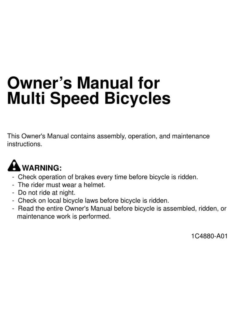
Owner’s Manual for
Coaster Brake Bicycles
This Owner's Manual contains assembly, operation, and maintenance
instructions.
WARNING:
- Check operation of brakes every time before bicycle is ridden.
- The rider must wear a helmet.
- Do not ride at night.
- Check on local bicycle laws before bicycle is ridden.
- Read the entire Owner's Manual before bicycle is assembled, ridden, or
maintenance work is performed.
- Keep these instructions for future reference.
- DO NOT RETURN THIS UNIT TO THE STORE -
If you have problems or questions, trained service representatives are available
to help you – please call Customer Service v092906
Your Model Number is:________________
(write your model number here)

HBC Limited Warranty
Part or model specifications are subject to change without notice.
This Limited Warranty is the only warranty for your HBC bicycle. There are no other express warranties.
The only uses for this product are described in this manual. Warranty registration is not required.
The Limited Warranty extends only to the original consumer and is not transferable to anyone
else.
What does this Limited Warranty cover?
This Limited Warranty covers all parts of the bicycle.
What must you do to keep the Limited Warranty in effect?
This Limited Warranty is effective only if:
- the bicycle is completely and correctly assembled;
- the bicycle is used under normal conditions for its intended purpose (see the following section
for excluded activities);
- the bicycle receives all necessary maintenance and adjustments.
What is not covered by this Limited Warranty?
The bicycle is designed for general transportation and recreational use only. This Limited Warranty
does not cover normal wear and tear, normal maintenance items, or any damage, failure, or loss
that is caused by improper assembly, maintenance, adjustment, storage, or use of the bicycle. This
Limited Warranty will be void if the bicycle is ever:
- used in any competitive sport;
- used for stunt riding, jumping, aerobatics or similar activity;
- installed with a motor or modified in any other way;
- ridden by more than one person at a time;
- rented;
- used in a manner contrary to the instructions in this Owner’s Manual.
HBC will not be liable for incidental or consequential loss or damage due directly or indirectly from
use of this product. Some States do not allow the exclusion or limitation of incidental or consequential
damages, so the above limitation may not apply to you.
For how long does this Limited Warranty last?
The frame is warranted for life except aluminum frames, which are warranted for ten (10) years.
The fork is warranted for life except for shock forks, which are covered by a one (1) year warranty.
All other components are warranted for six (6) months from the date of purchase.
What will HBC do?
HBC will replace, without charge to you, any frame, fork, or component found to be defective by
the HBC. The original owner must pay all labor and transportation charges connected with the
repair or warranty work.
How do you get service?
Contact the Customer Service Department.
What rights do you have?
This warranty gives you specific legal rights. You may also have other rights which vary from State
to State.

Owner’s Bicycle Identification Record
NOTE: This information is only available on the bicycle itself. It is not available from HBC.
Each HBC bicycle has a Model / Serial Number stamped into the frame or printed on a label. The
Model / Serial Number [1] can be found on the bottom of the crank housing, on the top of the crank
housing, or on the rear of the bicycle as shown. Write this number below to keep it for future reference.
If the bicycle is stolen, give this number and a description of the bicycle to the police. This will
help them find the bicycle.
You will also need this number if you order parts or request service information from our Customer
Service Department.
_ _ _ _ _ _ _ _ _ _ _ _ _ _ _ _ _ _ _
Model / Serial Number
Purchase Date ___________________________ Model Name ___________________________
Safety Information.
Meanings of the Safety Instructions
This symbol is important. See the word “CAUTION” or “WARNING” which follows it.
The word “CAUTION” is before mechanical instructions. If you do not obey these instructions,
mechanical damage or failure of a part of the bicycle can occur.
The word “WARNING” is before personal safety instructions. If you do not obey these instructions,
injury to the rider or to others can occur.

The Owner’s Responsibility
WARNING: This bicycle is made to be ridden by one rider at a time for general transportation
and recreational use. It is not made to withstand the abuse of stunting and jumping.
If the bicycle was purchased unassembled, it is the owner’s responsibility to follow all assembly and
adjustment instructions exactly as written in this manual and any “ Special Instructions” supplied with
the bicycle. The owner must make sure all components are securely attached.
If the bicycle was purchased assembled, it is the owner’s responsibility, before riding the bicycle for
the first time, to make sure the bicycle is assembled and adjusted exactly as written in this manual
and any “Special Instructions” supplied with the bicycle. The owner must make sure all components
are securely attached.
Fitting the Rider to the Bicycle
To determine the correct size of bicycle for the rider:
- Straddle the assembled bicycle with feet shoulder width apart and flat on the ground
- There must be at least one inch of clearance [1] between the highest part of the top tube [2] and the crotch
of the rider
- The minimum leg-length for the rider is the highest part of the top tube plus one inch [3].
- The rider must be able to easily reach and operate the brake levers (if so equipped).
Rules of the Road
WARNING: If this is your child's first bicycle, make sure the child understands and obeys the
following “Rules of the Road”.
WARNING: Failure of the rider to obey the following “Rules of the Road” can result in injury
to the rider or to others.

- Rider must have the skill to operate the bicycle safely. Every bicycle has different handling and
operation features. Practice riding on large, flat areas away from traffic and other hazards before
riding on the road.
- Always wear a bicycle helmet.
- Do not ride at night.
- Make sure the reflectors of your bicycle are correctly positioned. Do not remove the reflector or
replace the reflectors with lighted devices that look similar to reflectors.
- Make yourself more visible to motorists. Wear light-colored or reflective clothing, such as a
reflective vest and reflective bands for your arms and legs. Use reflective tape on your helmet.
Do not let anything cover the reflectors.
- If the bicycle has 16 inch or smaller wheels, ride only on sidewalks or on your own property. Never
ride on the street or in alleys that are used by motor vehicles.
- When riding with training wheels:
- Ride only on level areas.
- Do not ride on steep hills, uneven sidewalks, or near steps. The bicycle can tip over if a training
wheel goes off the edge of the riding surface.
- Ride straight up and down sloped surfaces, because the bicycle can tip over when riding across
sloped surfaces.
- Slow down at corners because you can not turn as quickly as bicycles without training wheels.
- Obey all traffic regulations, signs, and signals.
- Always wear shoes.
- Use extra caution in wet weather.
- Ride slowly on damp surfaces because the tires will slide more easily. Apply the coaster, caliper,
or cantilever brakes sooner than normal. Greater stopping distance is necessary, especially if
the wheel rims and tires are wet.
- Ride on the right side of the road, in a single file, and in a straight line.
- Be aware of drain grates, soft road edges, gravel or sand, pot holes or ruts, wet leaves, or uneven
paving.
- Avoid these hazards to prevent loss of control or damage to your wheels.
- Cross railroad tracks at a right angle to prevent the loss of control.
- Avoid unsafe actions while riding.
- Do not carry any passengers.
- Do not carry any items or attach anything to your bicycle that could hinder your vision, hearing,
or control.
- Do not ride with both hands off the handlebar.
If you have an all terrain style bicycle, obey these additional “Rules of Off-Road Riding”.
- Always wear the correct safety equipment.
- Use extreme caution when not riding on pavement.
- Do not ride in off-road conditions that are beyond your capabilities. Ride trails in relatively flat
areas that have few obstacles.
- Be sensitive to the environment, conscientious of the property on which you ride, and considerate
of others you may meet on the trail.
Introduction
This Owner’s Manual is made for several different bicycles. All features and components are not included on
all models. Some of the illustrations may not look exactly like the parts of the bicycle, but the instructions are
correct. If the bicycle has any parts that are not described in this manual, look for separate “Special
Instructions” that are supplied with the bicycle.
Do not dispose of the carton and packaging until you complete the assembly of the bicycle. This can prevent
accidentally discarding parts of the bicycle.
NOTE: All of the directions (right, left, front, rear, etc.) in this manual are as seen by the rider while seated
on the bicycle.
Attach and use only HBC brand accessories and replacement parts on the bicycle.
Tools Needed
Small Adjustable Wrench Large Adjustable Wrench
(Jaws must open at least 9/16 inch.) (Jaws must open at least 1 1/4 inch.)
Flat-blade Screwdriver Phillips Screwdriver
Slip-Joint Pliers Metric Allen Wrenches
(Needed on some models.)
Important Note
All features and components are not included on all models.
Many models come with accessories such as bottles, handlebar fairings, streamers etc... that may
affect the order of the assembly of the bicycle. Please look over all of the pieces that come with your
new bicycle and refer to the back section of the manual to see if there are any special requirements
associated with that accessory before beginning assembly.

Front Wheel
NOTE: If the bicycle does not have a front fender, go
to Step 2.
Step 1:
If the bicycle has a front fender, attach
it to the fork as shown.
Locate the fender in the fork with the upper
fork mounting tab on the rear side of the
fork.
Insert the fender screw (1) through the fork,
the washer (2), and the fender tab (3) - from front
to rear . (If the bicycle has a front brake
install the upper fender tab on the brake mounting
stud.)
Install the Nylock nut (4) on the screw and
tighten the assembly.
Insert each lower mounting screw through
the fender brace, and into the lower fork
mounting tab.
Tighten each screw sufficiently to hold the
fender in-place, be careful not to over tighten
and strip the screw threads.
Step 2:
Assemble the front wheel to the fork as shown:
- Make sure the tab of each wheel retainer [6] is in the
hole of the fork
NOTE: Some models have a front fork with a built in
wheel retention feature. (As shown in the lower
mounting screw photo.) The wheel retainers [6] are
not required and will not fit on a fork with this feature.
- Using the two nuts [7] with serrations [8], attach the
front wheel
WARNING: Do not use the nuts without
serrations to attach the front wheel.
- Put the wheel in the center of the fork and tighten both
nuts to the recommended torque of 21 ft.-lbs.
Fully Assembled
Upper Mounting Screw
Lower Mounting Screw

Training Wheels
Attach the legs to the bicycle frame:
- Put the alignment insert [1], a leg [2], and a nut [3] on
each end of the rear wheel axle [4]
- Make sure the tab of the alignment insert [5], is
to the rear of the axle and in the slot [6] of
the frame
- Make sure both training wheels are the same
distance from the ground
- Tighten the nuts securely.
Operation
WARNING: Before each ride, make sure both nuts are tight. Also make sure both training
wheels are the same distance from the ground.
As your child’s ability and balance improve, you may raise or remove the training wheels.
- To move the training wheels, loosen the nut, slide the leg to the correct position, and retighten the
nut.
- To remove the training wheels, remove the nut, leg, and alignment insert.
Quick Release Operation
-To release the clamp force on the component, move the Quick Release (QR) lever counterclockwise to
the open position.
-To apply the clamp force on the component, move the QR lever clockwise to the closed position.
-To adjust the clamp force of the QR, loosen or tighten the nut on the threaded end.
-You must use strong force to move the quick release lever to the “close” position. If you can easily
move the lever to the “close” position, the clamping force is too light.
-If the clamping force of the quick release mechanism is too light, the component can loosen while
riding. This can cause injury to the rider or to others.
WARNING! OPERATE THE QUICK RELEASE LEVER BY HAND ONLY. DO NOT USE A HAMMER
OR ANY OTHER TOOL TO TIGHTEN THE QUICK RELEASE LEVER.
WARNING! DO NOT TIGHTEN THE QUICK RELEASE MECHANISM BY TURNING THE LEVER IN
A CIRCULAR MOTION. THIS CAUSES THE CLAMPING FORCE TO BE TOO TIGHT.

Front Reflector Bracket and Clear Reflector Assembly
This section covers the assembly of the front reflector to the front reflector bracket. Determine which
style you have before beginning assembly.
Snap In Style Screw In Style
Reflector Assembly
Assemble the clear reflector to the front reflector bracket:
WARNING: Install the clear reflector exactly as shown or it will not operate correctly.
Snap In Style
- Push the reflector [1] onto the reflector bracket [2]
- Make sure the stud [3] on the reflector goes into the hole [4] of the bracket with a “snap” sound.
Screw In Style
- Put the reflector onto the reflector bracket
- Make sure the studs on the back of the reflector go into the holes of the reflector bracket
- Put the screw [?] through the bracket and into the reflector
- Tighten screw.

Front Reflector Bracket Installation
This section covers several different placements of the front reflector bracket. Make sure the front
reflector is vertical (perpendicular to the ground).
The front reflector bracket will mount on the fork or handlebar. Some models may already have the
brackets and reflectors installed. If the reflector is not installed, refer to the “Front Reflector Bracket
and Clear Reflector Assembly” section.
Determine which type of reflector bracket you have and its mounting location and then follow the
instructions for that style.
Top of Fork Bottom of Fork Handlebar Mount Handlebar Mount
Style 1 Style 2
Top of Fork
Attach the hardware to the fork:
- Remove and discard plastic cap [5] (if installed) on fork [6]
- Tighten bearing cone [7] by hand to make sure the bearings are tight
- Install reflector bracket and locknut [8]
- Tighten locknut.
Bottom of Fork
Attach the hardware to the fork:
- Remove and discard plastic cap [5] on fork [6]
- Tighten bearing cone [2] by hand to make sure the bearings are tight
- Install sheath stop [3] and locknut [4]. You may not have a sheath stop. If you do not, install a keyed
washer and locknut.
NOTE: The sheath stop barrel [11] is on the cable wire of the front cantilever brake. Install it during the
assembly of the brake.
- Tighten locknut.
Assemble the front reflector bracket and clear reflector to the fork:
- Attach the reflector bracket to the front of the fork with a bolt [9] and self locking nut [10]
- If necessary, adjust the angle of the front reflector bracket so the clear reflector is vertical (perpendicular
to the ground).

Handlebar Mount - Style 1 and Style 2
Assemble to the handlebar:
- Put the clamp [1] as near the handlebar stem as possible
NOTE: If you have Style 1, make sure the bracket points towards the
ground.
- Hold the reflector in this position and tighten the screw(s) [3].
Operation and Maintenance
WARNING: For your own safety, do not ride the bicycle if the
reflectors are incorrectly installed, damaged, or missing. Make
sure the front and rear reflectors are vertical. Do not allow the visibility
of the reflectors to be blocked by clothing or other articles. Dirty
reflectors do not work well. Clean the reflectors, as necessary, with
soap and a damp cloth.
Rear Reflector Bracket and Red Reflector Assembly
This section covers the assembly of the rear reflector to the rear reflector bracket. Determine which
style you have before beginning assembly.
Snap In Style Screw In Style
Reflector Assembly
Assemble the red reflector to the rear reflector bracket:
WARNING: Install the red reflector exactly as shown or it will not operate correctly.
Snap In Style
- Push the reflector [1] onto the reflector bracket [2]
- Make sure the stud [3] on the reflector goes into the hole [4] of the bracket with a “snap” sound.
Screw In Style
- Put the reflector onto the reflector bracket
- Make sure the studs on the back of the reflector go into the holes of the reflector bracket
- Put the screw [?] through the bracket and into the reflector
- Tighten screw.

Rear Reflector Bracket Installation
This section covers several different placements of the rear reflector bracket. Make sure the rear
reflector is vertical (perpendicular to the ground).
The rear reflector bracket will mount on the seat post, post clamp, or rear brace. Some models may
already have the brackets and reflectors installed. If the reflector is not installed, refer to the “Rear
Reflector Bracket and Red Reflector Assembly” section.
Determine which type of reflector bracket you have and its mounting location and then follow the
instructions for that style.
Seat Post Seat Post Post Clamp Rear Brace
Seat Post
Assemble the reflector bracket to the seat post:
NOTE: If the reflector bracket is too large for the seat post, put the rubber spacer inside the clamp.
- Make sure the red reflector [4] is vertical, points toward the rear of the bicycle, and has three
inches of clearance between the top of the seat and the top of the red reflector.
- Hold the red reflector in this position and tighten the screw(s).
Post Clamp
Put the rear reflector bracket on the post clamp:
- Make sure the rear reflector bracket points up
- Put the bolt through the reflector bracket and the post clamp [8]
- Install nut (or nut and washer)
- Do not tighten at this time.
Rear Brace
Install bracket on rear brace:
- Put bracket on brace so the bracket points up
- Install bolt and nut (also washer, if provided)
- Tighten securely.
Operation and Maintenance
WARNING: For your own safety, do not ride the bicycle if the reflectors are incorrectly
installed, damaged, or missing. Make sure the front and rear reflectors are vertical. Do not
allow the visibility of the reflectors to be blocked by clothing or other articles. Dirty reflectors do not
work well. Clean the reflectors, as necessary, with soap and a damp cloth.

Spoke Reflectors
Your bicycle may have one of the following styles of spoke reflectors. Many bicycles will come with the
wheel reflectors already attached. If your bicycle does not have the wheel reflectors attached,
determine which style you have and follow the instructions.
Assemble a reflector between the spokes of each wheel:
Style 1 – Bolt and nut
NOTE: If the bicycle has a wheel disc, put the reflector in
the notch of the wheel disc. The notch is shaped so the
spoke reflector fits into it.
- Make sure the center of each reflector [1] is less than
three inches from the inside edge of the wheel rim [2]
- Make sure the curve of the reflector [3] matches the
curve of the wheel rim [4]
- Install bolt and nut, then tighten.
Style 2 - Push pin
- Put fastener [6] over a spoke [7] and into each
reflector
- Push pin straight into reflector until a "snap" sound is
heard.
Style 3 - One-quarter turn
- Put fastener [6] over a spoke [7] and into each
reflector
- Turn fastener clockwise one-quarter of a turn.
Operation and Maintenance
WARNING: For your own safety, do not ride the bicycle if the reflectors are incorrectly
installed, damaged, or missing. Make sure the front and rear reflectors are vertical. Do not
allow the visibility of the reflectors to be blocked by clothing or other articles. Dirty reflectors do
not work well. Clean the reflectors, as necessary, with soap and a damp cloth.

Handlebar and Stem
The bicycle may have different styles of handlebar stems. One style mounts inside the fork while the
other mounts around the outside of the fork. Follow the instructions for the style that you have.
Assembly
Assemble the stem to the fork:
Insidemountstyle Inside mount
- If necessary, assemble the stem bolt [4], washer [10],
and wedge nut [11] to the stem [1]
- Point the stem [1] toward the front of the bicycle
- Put the stem at a comfortable height for the rider.
WARNING: To prevent steering system
damage and possible loss of control, the “MIN-IN”
(minimum insertion) mark [3] on the stem must be inside
the locknut.
- Tighten the stem bolt just enough that the stem will
not fall into the locknut.
Assemble the handlebar to the stem:
- Put the handlebar [5] into the stem, but do not tighten
the handlebar clamp [6] at this time.
- Align the stem with the front wheel and tighten the stem bolt.
Assemble the brake lever(s) to the handlebar.
- Loosen the clamp screw of each brake lever.
- If necessary, move the handlebar to each side to install the brake lever(s).
- Put the brake lever(s) on the handlebar with the brake lever for the rear brake on the right side of the
handlebar.
- Do not tighten the clamp screws at this time.
Tighten the stem bolt and the handlebar clamp:
WARNING: Do not over tighten the stem bolt. Over tightening the stem bolt can damage
the steering system and cause loss of control.
- Make sure the stem is aligned with the front wheel and tighten the stem bolt
- Put the handlebar in a comfortable position for the rider
WARNING: If the handlebar clamp is not tight enough, the handlebar can slip in the stem.
This can cause damage to the handlebar or stem, and can cause loss of control.
- Tighten the bolt(s) of the handlebar clamp
- If the handlebar clamp has more than one bolt, tighten the bolts equally using a criss-cross pattern.
Test the tightness of the stem:

- Straddle the front wheel between your legs
- Try to turn the front wheel by turning the handlebar
- If the handlebar and stem turn without turning the front wheel, realign the stem with the wheel
- Tighten the stem bolt(s) tighter than before (about 1/2 revolution only at a time)
- Do this test again, until the handlebar and stem do not turn without turning the front wheel.
Test the tightness of the handlebar clamp:
- Hold the bicycle stationary and try to move the ends of the handlebar forward or backward
- If the handlebar moves, loosen the bolt(s) of the handlebar clamp
- Put the handlebar in the correct position
- Tighten the bolt(s) of the handlebar clamp tighter than before
- If the handlebar clamp has more than one bolt, tighten the bolts equally
- If the handlebar clamp has 4-bolts, see 4-Bolt Stem section that follows.
- Do this test again, until the handlebar does not move in the handlebar clamp.
Assemble the grips to the handlebar:
- Mix 5 drops of liquid soap in a cup of water.
- Wet the handlebar and the inside of each grip [1] with the soap mixture
- Using a twisting motion, push each grip fully on the handlebar
- If the grips are open on both ends, push a plastic plug into the end of
the handlebar.
WARNING: Use only soap and water to install the grips. The grips may slip while wet.
Allow the grips to completely dry before riding the bicycle.
Put the brake levers in the correct position:
- Put each brake lever against the grip in a position that is comfortable to the rider.
- Tighten the clamp screw of each brake lever.
4-Bolt Stem Instructions
-Align the stem in the steertube so that the handlebar is perpendicular with the front wheel.
-Ensure the minimum insertion mark on the stem is not visible - beneath the top of the steertube.
-Tighten the stem bolt enough so that stem will not rotate in the steertube.
-Check the rotation with firm pressure.
-Adjust and tighten the handlebar in the stem.
-Tighten the 4 bolts in a criss-cross pattern, and ensure they clamp evenly.
-Tighten the handlebar clamp nuts enough so that handlebar will not rotate in the stem.
-Check handlebar rotation with slight pressure.

Coaster Brake
Operation
Operate the coaster brake as follows:
- Push the pedals backward to move the chain backward
- The chain activates the coaster brake mechanism that is inside the rear wheel hub
- As you push the pedals backward with increasing force, the braking action of the coaster brake
increases.
If your bicycle has a caliper brake(s) in addition to the coaster brake, always use the coaster brake as
the main brake to stop the bicycle.
WARNING: If you do not obey the following instructions, injury to the rider or to others can
occur:
- When you ride the bicycle the first time, test the
coaster brake and practice using it at a low speed in a
large level area that is free of obstructions.
- Every time the bicycle is ridden, make sure the clamp
[1] on the brake arm [2] is securely attached to the
chain stay [3] of the bicycle frame. The coaster brake
will not work correctly if the brake arm is not attached
to the chain stay.
- Always try to brake while going in a straight line. If you must brake while turning; when the
pavement is wet; or when the pavement is covered with sand, gravel, or leaves, start to brake
sooner than normal and apply the brake intermittently to reduce the chance of skidding.
- Be careful when riding downhill or at a high speed because as your speed increases, a longer
distance to stop the bicycle will be necessary. Slow for curves because too much speed can
force you to make a turn that is too wide.
- Have the coaster brake repaired by a bicycle service shop the first time you notice that it does not
stop the bicycle quickly and smoothly or just does not work as well as it has in the past.
Maintenance
Every two years, more often if you ride in dusty or dirty conditions, have a bicycle service shop clean
and lubricate the parts of the coaster brake that are inside the rear wheel hub.

Seat
Assembly
If the seat does not come pre-assembled to the seat post,
assemble the seat to the seat post: as shown:
- Make sure the seat post [10] is fully through the seat clamp [11]
- Tighten the seat clamp so the seat [12] stays on the seat post.
- If the seat clamp has a nut on each side, tighten both
nuts equally.
If the bicycle has a seat post bellows or seat post tights
[13], push the bellows or tights fully onto the seat post.
NOTE: If necessary, push the bellows or tights together
so you can see the “MIN-IN” mark [15] on the seat
post.
Point the seat forward and put the seat post into the seat tube.
Put the seat and the red reflector in the correct position
and tighten the post clamp or quick-release lever:
- Put the seat at a comfortable height for the rider
Assemble the seat to the seat post or seat pillar:
The bicycle may have a seat post or seat pillar. Determine which style you have and follow the instructions.
Seat Post Style
- Put the seat post [10] fully through the seat clamp [11]
- Tighten the seat clamp so the seat [12] stays on the seat post
- If the seat clamp has a nut on each side, tighten both nuts equally
Seat Pillar Style
- If the seat has a clamp attached, remove and discard the clamp
- Put the seat rails between the seat clamp and tighten the clamp.
Point the seat forward and put the seat post or seat
pillar into the seat tube.
- Make sure you can not see the “MIN-IN” minimum
insertion mark [13] of the seat post above the seat tube
- Install a bolt, washer (if supplied), and nut or a quick release
lever
- Put the seat at a comfortable height for the rider
WARNING: The red reflector must be vertical, point straight toward
the rear of the bicycle, and have three inches of clearance between the top
of the seat and the top of the red reflector.
- Tighten the bolt and nut or quick release lever

Install the seat post into the seat tube:
CAUTION: If you accidentally drop the seat post
into the seat tube, it may be difficult to remove it.
Install post clamp on seat tube:
- Put the clamp on the seat tube. Push the clamp
[1] down so you can see 1/16 inch [2] of the seat tube
[3] above the clamp.
NOTE: Some post clamps are welded in position and can not be moved.
- If the post clamp has a raised edge, make sure the raised edge is against the top of the seat tube.
Assemble the red reflector to the rear reflector bracket:
- Push the rear reflector bracket [4] into the back of the
red reflector [5]
- Make sure the stud [6] of the red reflector goes into
the hole [7] of the rear reflector bracket.
Assemble the rear reflector bracket to the post clamp
with hardware:
WARNING: Install the rear reflector bracket
exactly as shown or the visibility of the red
reflector will be reduced.
- Install a bolt [9] and nut [8] or a quick release
lever (see Quick Release Operation section) as shown
- Do not tighten the bolt and nut or quick release
lever at this time.
WARNING: Every time you loosen the quick release mechanism, make sure the red reflector
is correctly positioned if the reflector is mounted on the seat post or seat pillar.
- Try to turn the seat side-to-side and to move the front of the seat up and down
- If the seat moves in the seat clamp
- Loosen the seat clamp
- Put the seat in the correct position and tighten the seat clamp tighter than before
- Do this test again, until the seat does not move in the seat clamp
8
9

If the seat post moves in the seat tube:
- Loosen the bolt and nut
- If you have a quick release lever, move it to the “open” position (see Quick Release Section).
- Put the seat in the correct position and tighten the bolt and nut or quick release tighter than before
- If you have a quick release lever, move the lever to the “close” position
- Do this test again, until the seat post does not move in the seat tube.
Operation and Maintenance
WARNING: For your own safety, do not ride the bicycle if the reflectors are incorrectly installed,
damaged, or missing. Make sure the front and rear reflectors are vertical. Do not allow the visibility of the
reflectors to be blocked by clothing or other articles. Dirty reflectors do not work well. Clean the reflectors, as
necessary, with soap and a damp cloth.
WARNING: Do not ride the bicycle if the “MIN-IN” minimum insertion mark of the seat post is not
inside the seat tube.
- Make sure you can not see the “MIN-IN” minimum insertion mark of the seat post above the seat tube
- Make sure there at least three inches of clearance between the top of the seat and the top of the red
reflector
- Make sure the red reflector is vertical and points straight toward the rear of the bicycle.
- With the seat and the red reflector in the correct position, tighten the post clamp bolt and nut or quick
release lever
- To tighten the quick release lever:
- Move the lever so it points straight away from the bicycle
- Tighten or loosen the adjusting nut so the lever meets resistance when the lever is at this
position
- Push the lever down to the closed position.
- Test the tightness of the seat clamp and the post clamp.
WARNING: Every time you loosen the post clamp, make sure the red reflector is correctly
positioned. The red reflector must be vertical, point straight toward the rear of the bicycle, and have three
inches of clearance between the top of the seat and the top of the red reflector.
Try to turn the seat side-to-side and to move the front of the seat up and down
If the seat moves in the seat clamp
- Loosen the seat clamp
- Put the seat in the correct position and tighten the seat clamp tighter than before
- Do this test again, until the seat does not move in the seat clamp
If the seat post moves in the seat tube:
- Put the seat in the correct position and tighten the post clamp tighter than before
- Do this test again, until the seat post does not move in the seat tube.
Operation and Maintenance
WARNING: For your own safety, do not ride the bicycle if the reflectors are incorrectly
installed, damaged, or missing. Make sure the front and rear reflectors are vertical. Do not
allow the visibility of the reflectors to be blocked by clothing or other articles. Dirty reflectors do not
work well. Clean the reflectors, as necessary, with soap and a damp cloth.

Brake Systems
Adjustments
WARNING: You must adjust the front and rear brakes as written before you ride the bicycle.
Put the brake shoes in the correct position:
- Loosen the nut [10] of each brake shoe
- Adjust each brake shoe so it is flat against the rim and aligned with the curve of the rim
- Make sure each brake shoe does not rub the tire
- If the surface of the brake shoe has arrows, make sure the arrows point toward the rear of the
bicycle
- Hold each brake shoe in position and tighten the nut.
Test the tightness of each brake shoe:
- Try to move each brake shoe out of position
- If a brake shoe moves, repeat the first step,
but tighten the nut tighter than before
- Do this test again, until each brake shoe does not move.
Stretch the cable:
- Hold both brake shoes against the rim
- Loosen the cable clamp
- Pull the cable tight and tighten the cable clamp
WARNING: Do not over tighten the cable clamp. Over tightening the cable clamp may cut
the cable and cause injury to the rider or to others.
- Squeeze each brake lever firmly 20 times
- Hold both brake shoes against the rim and loosen the cable clamp
-Pull the cable tight and tighten the cable clamp.
The following sections describe final brake system adjustments required before riding.
Determine which style you have and follow the instructions.
Sidepull Brake Cantilever Brake
Table of contents
Other Huffy Bicycle manuals

Huffy
Huffy BMX User manual

Huffy
Huffy Green Machine User manual

Huffy
Huffy cruiser User manual

Huffy
Huffy 700c User manual

Huffy
Huffy KD58C-LCD User manual

Huffy
Huffy Mountain Bikes User manual

Huffy
Huffy BMX bicycles User manual

Huffy
Huffy CLASSIC TRIKE User manual

Huffy
Huffy m0743 User manual

Huffy
Huffy 1C4880-A01 User manual

Huffy
Huffy Green Machine User manual

Huffy
Huffy Folding Trike User manual

Huffy
Huffy Green Machine User manual

Huffy
Huffy Minnie Lights & Sound User manual

Huffy
Huffy coaster User manual

Huffy
Huffy Slider User manual

Huffy
Huffy Mountain Bikes User manual

Huffy
Huffy M0782 User manual

Huffy
Huffy coaster User manual

Huffy
Huffy cruiser User manual