DENAGO CITY 2 User manual

QUICKSTART
GUIDE
CITY MODEL 2

With over 100 years collectively in the bike industry, our team loves to share
with you what we learned from riding, working in bike shops
and working in the bike industry.
We are looking forward to you joining us for a ride.

THANK YOU and welcome to the Denago team.
We value and appreciate you and your choice.
If there is anything you need, please reach out
and let us know how we can help.
Email: [email protected]
Call Us: 877-755-2453 (BIKE)
ALWAYS WEAR A HELMET
Please make sure you read, understand and follow the instructions
in the quickstart guide as eBikes are new to most riders.
For more information, please visit:
denago.zendesk.com

CITY MODEL 2 5 | DENAGO
CITY MODEL 2
6 | DENAGO QUICKSTART GUIDE
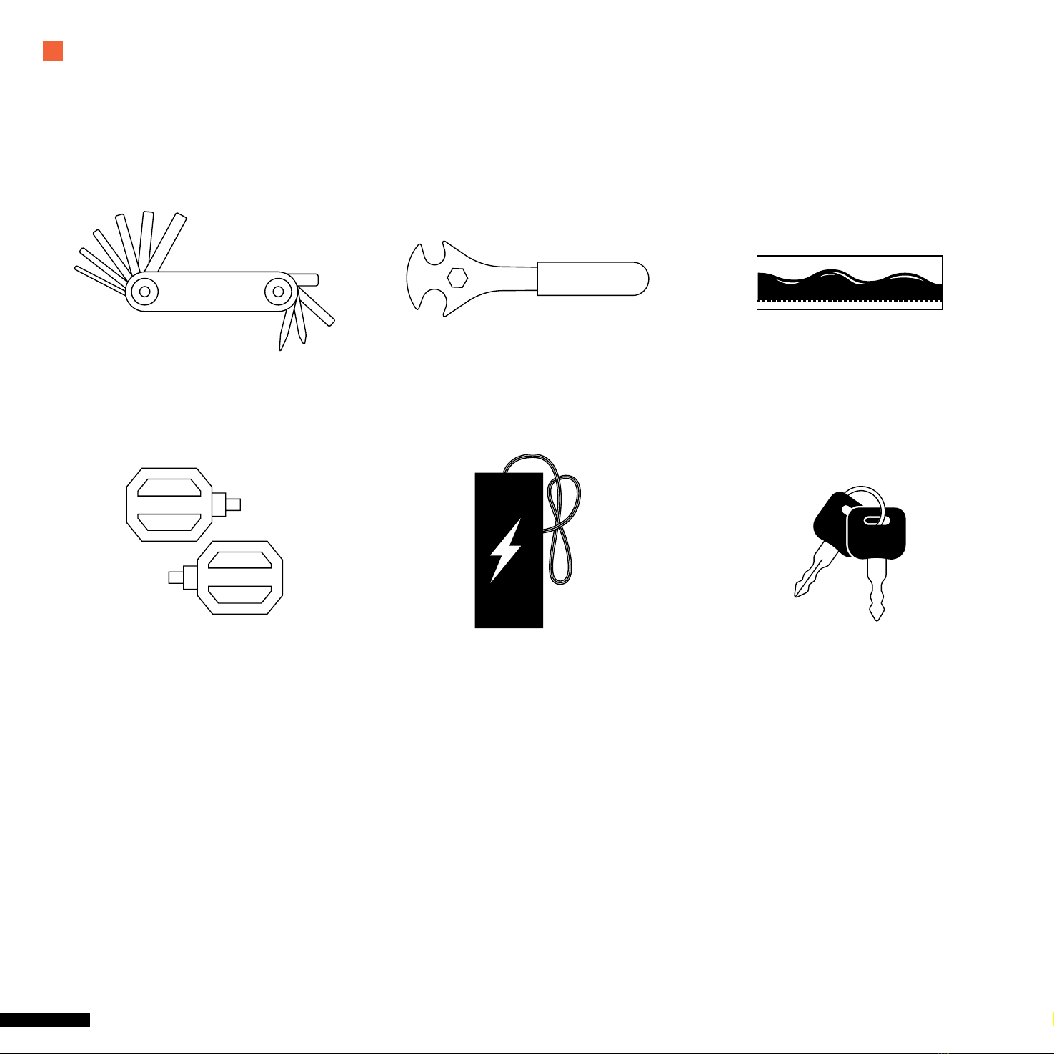
WHAT’S IN THE BOX
The following accessories are included with your 90% pre-assembled Denago bike.
Pedal Battery Charger Battery Keys
Multi Tool Pedal / Wheel Wrench Bicycle grease packet

YOUR DENAGO BIKE IS 90% ASSEMBLED
The quickstart guide will assist you in completing the assembly
By following the directions, you will be able to get outside and start
riding your new Denago eBike in less than 30 minutes.
If you are not comfortable or confi dent, please take your
bike to your local shop and ask for assistance.

GETTING STARTED
CITY MODEL 2 9 | DENAGO
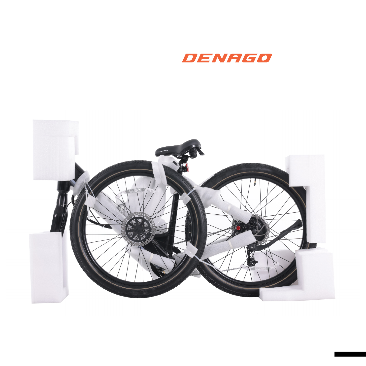
Unpack and Unwrap your eBike
10 | DENAGO QUICKSTART GUIDE
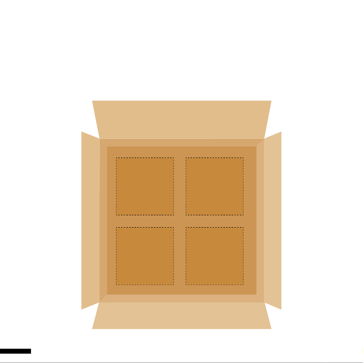
LAY OUT THE PARTS AND TOOLS
We’d like to make your assembly process a bit easier.
So we made a Parts & Tools layout inside the box.
Please lay Parts & Tools into each area.
Tool Set Front Wheel
& Parts
Pedals Other Stu

ASSEMBLY STEPS
1. HANDLEBAR
2. SEAT
3. FRONT WHEEL & BRAKE
4. PEDALS
5. MONITOR

12 | DENAGO QUICKSTART GUIDE
HANDLEBAR COMPONENTS HAS BEEN PRE-ASSEMBLED
Please tighten and secure all bolts
1. Unscrew the bolts and remove the
covers, bolts and sleeves, leaving all
washers in place.
2. Place the handlebar riser on the
front fork, tighten the bolts on the top
of the stem, and x the stem on the
front of the bicycle.
3. Loosen the xing screws between the
stem and the handlebar, and adjust
the handlebar to an angle which is
comfortable for riding.
4. Align the handlebar with the center
position, tighten and x the bolts on
both sides of the handlebar.
5. Add Top Cap to Stem Bolt. 6. Upon nal assembly, revisit this step
to conrm alignment with stem
and front wheel.
You will use the 5mm allen key on the multi tool for these steps.
ASSEMBLY | HANDLEBAR
NOTE: BRACKET ON FRONT OF STEM ARE
FOR AN AFTERMARKET FRONT HEADLIGHT.

CITY MODEL 2 13 | DENAGO
Front Reector Installation.
Remove the screw and place bracket over the handlebar on the
left side closest to the monitor, if you are sitting on the seat.
Tighten and secure the screw.
Monitor Installation.
Remove bolts and place monitor on
handlebar with a bracket on each side of the stem. Make sure
that you can clearly see the monitor while sitting the the seat.
Insert the bolts - tighten and secure.
You will need the 3mm allen key on the multi tool to install.
You will need the +/phillips screw driver in the multi tool to install.
14 | DENAGO QUICKSTART GUIDE
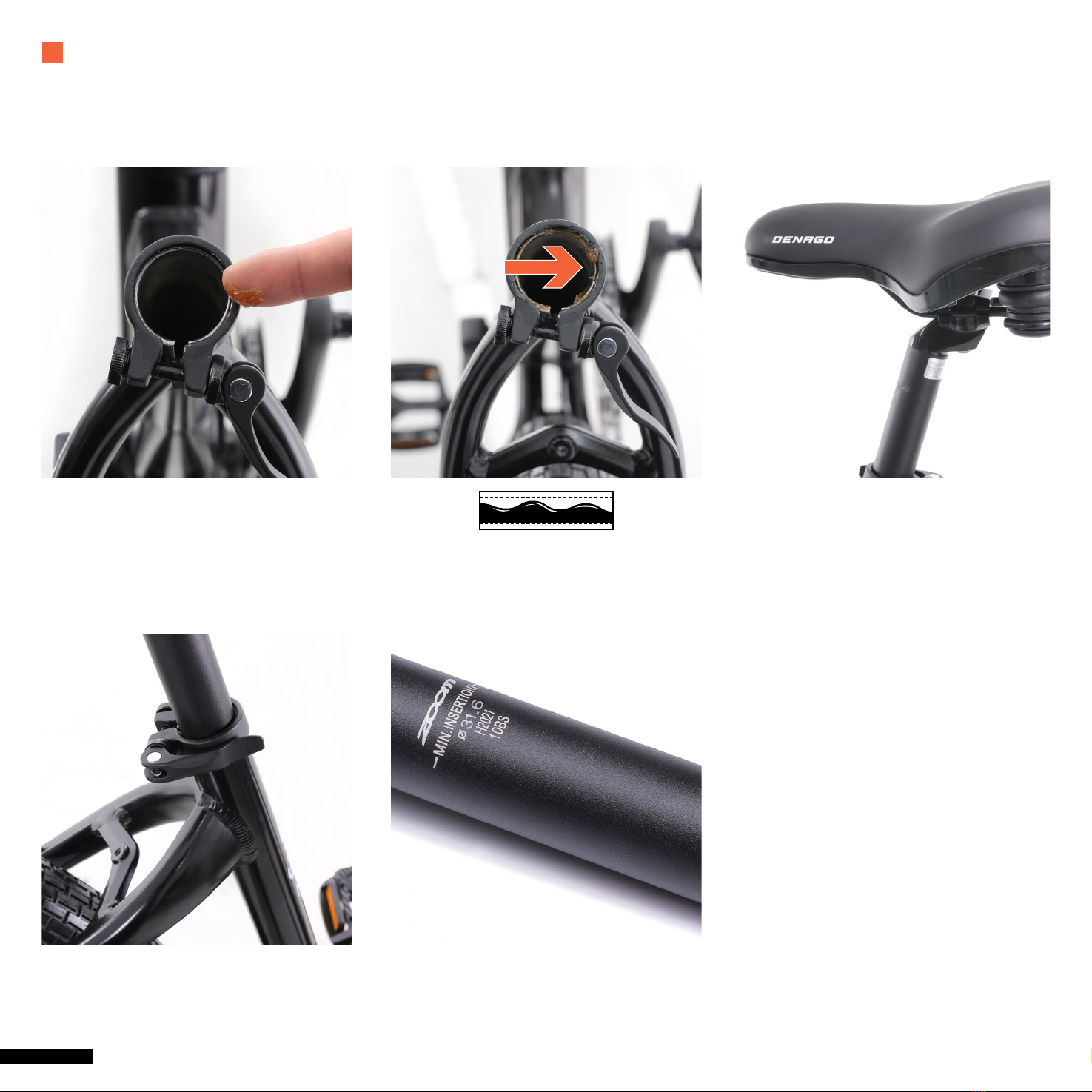
THE SEAT WAS PRE-ASSEMBLED
1. Open the seat clip and apply grease to
the inside of seat tube
3. Place Seat Post inside Seat Tube
- Insert past MIN Insertion Marking.
4. Adjust the seat height. Clamp secure/
tighten the quick release clamp.
CAUTION
Make sure seat post is
inserted to at least minimum
insertion markings are NOT visible
ASSEMBLY | SEAT
15 | DENAGO
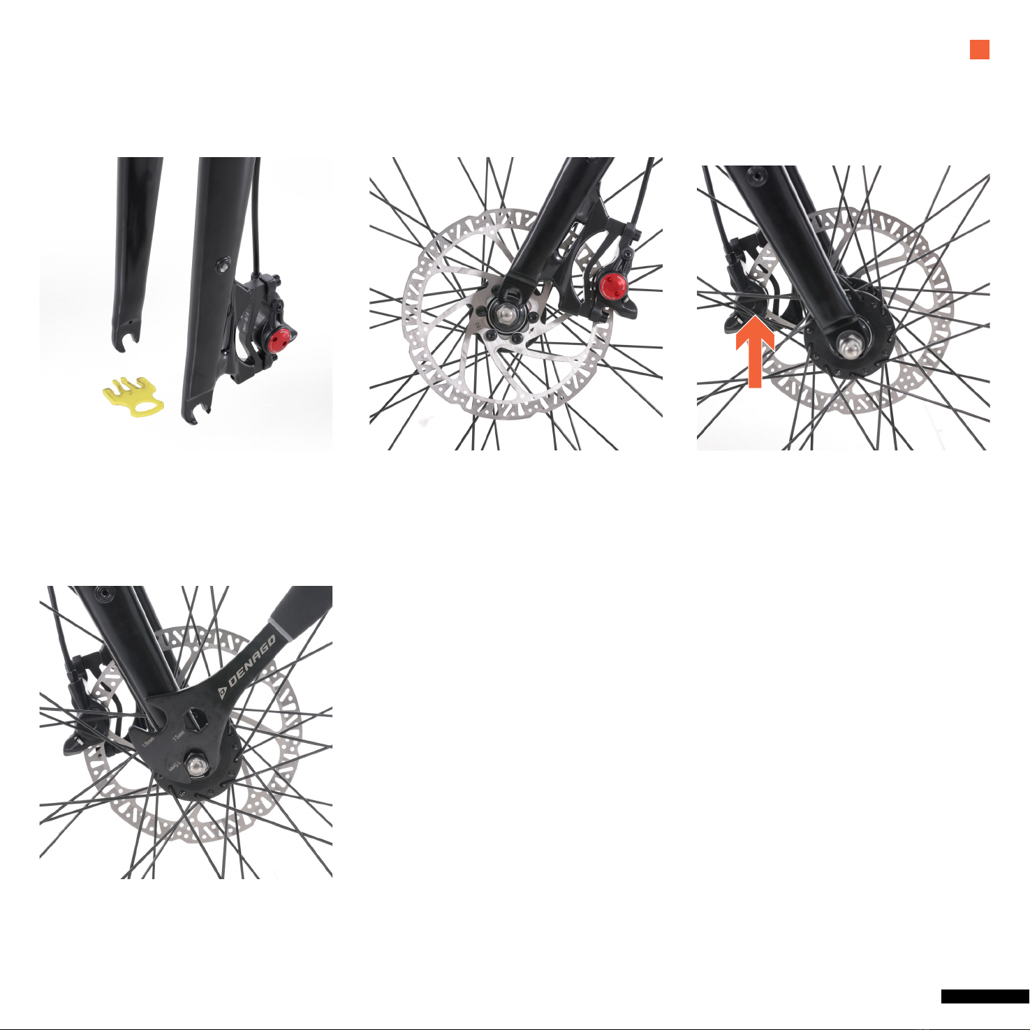
YOUR BIKE HAS A BOLT ON MECHANISM
1. Remove Packing Block from disc brake
caliper – Do Not Throw Away – Re-install
Packing Block whenever you remove
your front wheel.
2. Position the front wheel so it’s
centered between the front fork legs
with the axle resting inside
the fork drop outs.
3. Align the disc brake rotor so it is
centered in the slot of the brake caliper.
4. Tighten one axle nut part way then
tighten the other nut, repeat until both
sides are tightened securely.
Be sure that the wheel is centered
between the fork legs.
CAUTION
Tighten nuts securely to the fork dropouts
FRONT WHEEL & BRAKE | ASSEMBLY
NOTE: IF MISSING AXEL NUT CHECK THE BLACK PACKAGING DISC IT MIGHT BE STUCK INSIDE

Do NOT touch the brake rotor, especially while in
motion. Be CAUTIOUS and do not allow oils to be
applied or added to the DISC/ROTOR. This can
cause squeaking and decrease braking performance.
Improper installation of the front wheel and or
handlebar stem can cause loss of control, accidents,
serious injury or death. Check regularly that the front
wheel and handlebar stem are ALWAYS properly
secure and in good working condition.
WARNING
CITY MODEL 2 17 | DENAGO
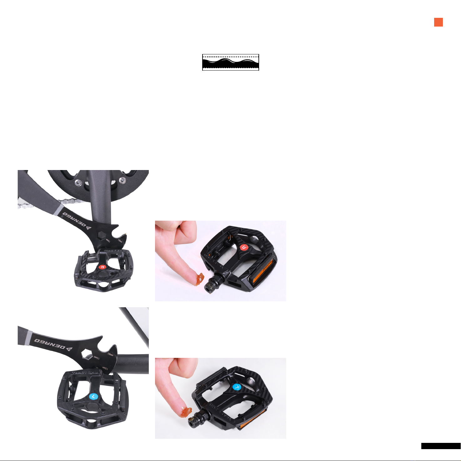
1. Drive Side of Bike select R-Right pedal
2. Apply grease to pedal threads
3. Insert Pedal into Crank/Drive side and start to turn CLOCKWISE.
4. Once hand tight apply pedal wrench to pedal and tighten and secure.
1. NON Drive Side of Bike select L-Left pedal
2. Apply grease to pedal threads
3. Insert Pedal into Crank Arm/NON- Drive side and start to turn COUNTER CLOCKWISE.
4. Once hand tight apply pedal wrench to pedal and tighten and secure.
PEDALS | ASSEMBLY
Apply grease to threads on both Left and Right Pedal.
MATCH PEDAL and CRANK ARM CAREFULLY
Right pedal is applied to drive side/side with crank and gears and threads/twist on CLOCKWISE
Left pedal is applied on NON-DRIVE side/side with disk rotors and twist COUNTERCLOCKWISE
USE PEDAL WRENCH AND CONFIRM PEDALS ARE TIGHTENED AND SECURE
Check frequently
18 | DENAGO QUICKSTART GUIDE
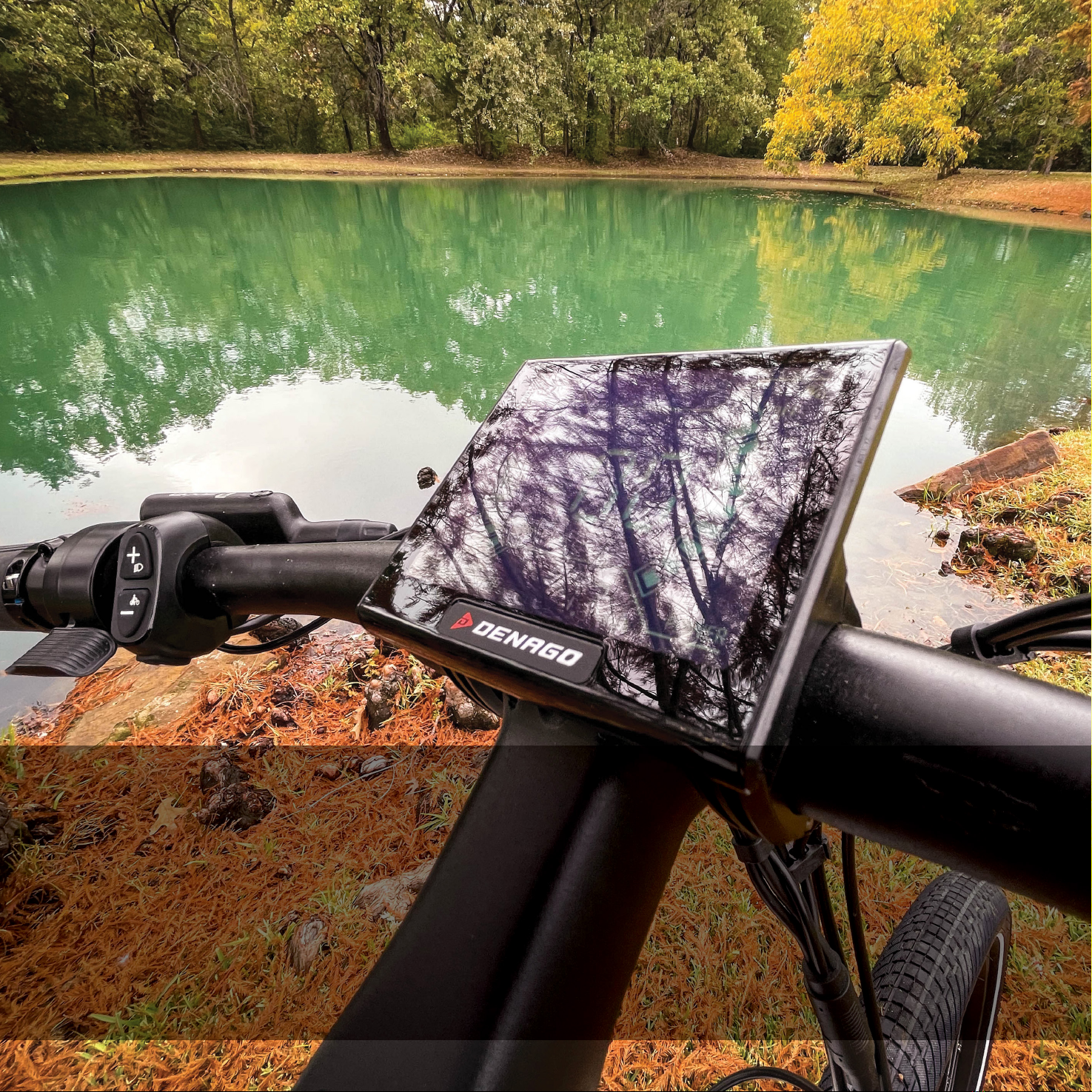
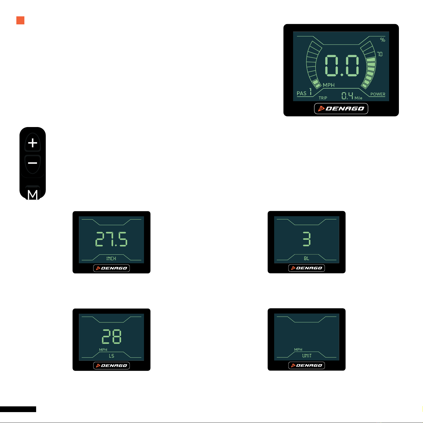
The monitor is connected in a number of ways to your eBike. It interfaces with the HMI
to adjust your PAS levels, advises if you have a problem with your brakes and alsotracks
a number of great features. Like speed, distance, MAX speed, battery level etc.
The following will show you how to conrm and make needed adjustments.
STEP 1 – Press and hold M (MODE) button until screen turns to either MAX speed or AVE speed.
STEP 2 – Press and hold + - (UP/Down)
simultaneously for 2-4 seconds until screen ashes and goes to setting interface.
You have 4 settings, use the +-to toggle thru each screen and the M to move to the next setting.
SETTING 1 – inCH: Wheel size setting.
Your Denago City 2.0 is 27.5.
SETTING 2 – LS: Limited Speed.
This is your max speed setting.
SETTING 3 – BL: This is screen brightness.
You have 3 levels.
SETTING 4 – unit: This is the speed
and distance setting MPH or KPH.
ASSEMBLY | MONITOR
RIDE READY SCREEN

CITY MODEL 2 19 | DENAGO
STEP 0 – Locate the HMI - Human Machine Interface.
STEP 1 – Press M (MODE) button to engage screen.
STEP 2 – Press + - (UP/Down) simultaneously for 2-4 seconds
until screen ashes and goes to setting interface.
STEP 3 – First screen to pop up is wheel size.
Press M (MODE) to go to next screen.
The following instructions will outline how you set the MAX Speed in Pedal Assist (PAS) level 5.
Once this is set it will adjust each of the other levels by a preset percentage.
STEP 4 – Limited Speed mode - (LS) this is where you
can adjust MAX speed.
Use the + - (UP/Down) to adjust MAX limit.
Your range is 28 –11 mph as the lowest limit.
STEP 5 – Press M (MODE) for 2 seconds
to return to main screen. You are ready to ride.

20 | DENAGO QUICKSTART GUIDE
Denago City 2.0 PAS (Pedal Assist System) comes with the ability to set your MAX speed while also adjusting your PAS level speeds.
Custom Pedal Assist Settings - The rider is able toadjust the MAX speed setting with 18 micro adjustments
• 28mph MAX down to 11mph
• With adjustment it will proportional adjust each of the other PAS levels accordingly (chart included)
• Adjustment made with 4 easy steps
• Easy to do anywhere
• Allows for better rider comfort, control, condence, and safety
• Assist in better pedal engagement when rider preferred settings are achieved
MPH PAS1 PAS2 PAS3 PAS4 PAS5
28 16.8 19.6 22.4 25.2 28
27 16.2 18.9 21.6 24.3 27
26 15.6 18.2 20.8 23.4 26
25 15 17.5 20 22.5 25
24 14.4 16.8 19.2 21.6 24
23 13.8 16.1 18.4 20.7 23
22 13.2 15.4 17.6 19.8 22
21 12.6 14.7 16.8 18.9 21
20 12 14 16 18 20
19 11.4 13.3 15.2 17.1 19
18 10.8 12.6 14.4 16.2 18
17 10.2 11.9 13.6 15.3 17
16 9.6 11.2 12.8 14.4 16
15 9.1 10.5 12 13.5 15
14 8.4 9.8 11.2 12.6 14
13 7.8 9.1 10.4 11.7 13
12 7.2 8.4 9.6 10.8 12
11 6.6 7.7 8.8 9.9 11
ASSEMBLY | MONITOR
Table of contents
Other DENAGO Bicycle manuals


