Denali DialDim DNL.WHS.20500 User manual

Instruction Rev01
0mm 10 20 30 40 50 60 70 80 90
Thank you for choosing DENALI
We know you would rather be riding your bike than wrenching on it, so we go the extra
mile to make sure our instructions are clear and as easy to understand as possible. If
you have any questions, comments, or suggestions don’t hesitate to give our experts
a call at 401.360.2550 or visit WWW.DENALIELECTRONICS.COM
Please Read Before Installing
DENALI products should always be installed by a qualified motorcycle technician. If
you are unsure of your ability to properly install a product, please have the product
installed by your local motorcycle dealer. DENALI takes no responsibility for damages
caused by improper installation. Caution: When installing electronics it is extremely
important to pay close attention to how wires are routed, especially when mounting
products to the front fender, front fork, or fairing of your motorcycle. Always be sure
to turn the handlebars fully left, fully right, and fully compress the suspension to
ensure the wires will not bind and have enough slack for your motorcycle to operate
properly.
Installation Tips
We strongly recommend using medium strength liquid thread locker on all screws and
bolts. It is also important to ensure that all hardware is tightened to the proper torque
specifications as listed in your owner’s manual. For included accessory hardware
please refer to the default torque specifications provided below. Inspect all hardware
after the first 30 miles to ensure that proper torque specifications are maintained.
Hardware Sizing Guide
Not sure what size bolt you have? Use this ruler to measure screws, bolts, spacers, etc.
Remember, the length of a screw or bolt is measured from the start of the “mounting
surface” to the end of the screw, so only include the screw head when measuring
countersunk screws.
M3 10.0 in-lbs - 1.0 Nm
M4 23.0 in-lbs - 2.5 Nm
M5 44.5 in-lbs 3.5 ft-lbs 5.0 Nm
M6 78.0 in-lbs 6.5 ft-lbs 9.0 Nm
M8 - 13.5 ft-lbs 18.0 Nm
M10 - 30.0 ft-lbs 41.0 Nm
M12 - 52.0 ft-lbs 71.0 Nm
in-lbs
ft-lbs NmBolt Size
0in 1 2 3
What’s In The Box?
DENALIELECTRONICS.COM
DialDim™ Lighting Controller
DNL.WHS.20500
Instruction Manual
(a) DialDim™ Controller.............................................................Qty 1
(b) DialDim™ Switch.................................................................Qty 1
(c) 7/8” Switch Mounting Band...................................................Qty 1
(d) M3.5x6 DIN 912..................................................................Qty 2
(e) Trigger Wire Harness............................................................Qty 2
(f) Light Extenson Cables...........................................................Qty 4
(a)
(b)
(c)
(d)
(e)

1. Device Overview
1.1 - Overview of Controller
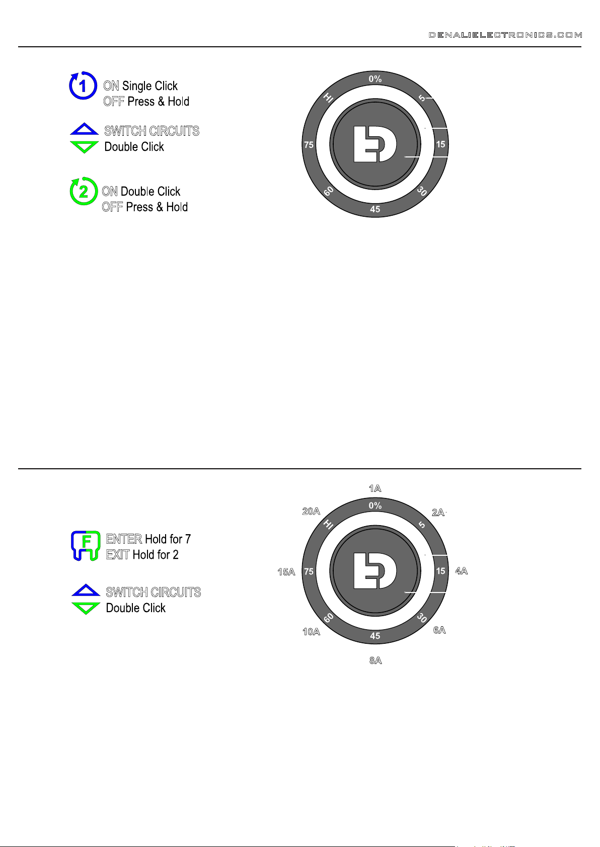
The DENALI DialDim™ Lighting Controller features a multicolor halo a
dimming switch that allows you to independently turn on/off and dim two
sets of auxiliary lights from a single consolidated wiring harness. The LED
halo switch displays your exact settings and allows for effortless dimming
on the fly. The blue halo controls light set one and the green halo controls
light set two; simply double click to switch between the two circuits.
The controller also features high beam, turn signal, and horn inputs to
unlock intelligent flash features that can cancel your auxiliary lights with
your turn signal, flash your auxiliary lights as a turn signal, or strobe your
lights when you sound your horn.
The dedicated light outputs are labeled and color coded so adding one or
two sets of lights to you vehicle couldn't be any easier. Connect your main
lights to the blue leads and your 2nd set of lights (typically fog or visibility
lights) to the green leads.
In addition to the DialDim Controller and Switch, the kit includes four 60”
plug-&-play light extensions and a 7/8” handlebar switch mount. Simply
add the light pods and you’re ready to ride!
DENALIELECTRONICS.COM
2. Features Overview
Switched Power
Circuit One Left
Circuit Two Left
Circuit Two Right
Circuit One Right
Main Fuse (30A)
High Beam
Horn
Right Turn
Left Turn
Battery Positive
Battery Negative
DialDim™
Switch
DialDim™
Controller
HI
LOW
ON
OFF
eFUSE
0-100
On/Off & Dim
Independently control two sets of lights
on/off and intensity level using the single
DialDim™ Switch. The blue halo controls
light set one and the green halo controls
light set two. Double click to switch
between the two circuits.
High/Low Sync
Your auxiliary lights will automatically
switch between your selected dim setting
to full intensity with the factory high
beam switch. Simply connect the blue
input wire to your vehicle high beam
circuit to enable this feature.
Stealth Mode
A clever 0% dim setting on the switch
allows your lights to be "off" during
normal driving conditions but will jump to
100% intensity with your vehicle high
beam switch. The lights will also react to
turn signal and horn inputs in this mode
but will remain off when no inputs are
detected.
Cancel with Turn Signal
When enabled the main lights (blue
circuit 1) will cancel in sync with your
signal to prevent "washing out" your
factory turn signal. Simply connect the
yellow and orange input wires to your
vehicle turn signal circuit to enable this
feature.
Flash as Turn Signal
When enabled your amber visibility lights
(green circuit 2) will flash in sync with
your factory turn signals. Simply connect
the yellow and orange input wires to your
vehicle turn signal circuit to enable this
feature.
Strobe with Horn
When enabled your auxiliary lights on
both circuits will strobe at 4Hz when you
sound your horn. Simply connect the
green input wire to your vehicle horn
circuit to enable this feature.
Electronically Fused Circuits
Both light circuits are electronically fused
and can be set right from the switch
itself! The halo will illuminate red to
notify you when a circuit fused is tripped.
Voltage Display Indicator
Upon vehicle startup, the switch halo will
flash green to indicate a healthy battery
voltage, or flash red to indicate a battery
voltage that is below 11.8v.
Low Voltage Cutoff
If battery voltage drops below 10.8v the
lights will not power on preventing you
from being stranded. The switch halo will
flash 4 red LEDs to indicate the low
voltage condition.

4. Mounting The Switch
DENALIELECTRONICS.COM
3. Installing The Harness
Circuit One - Left Aux Light
Circuit Two - Left Aux Light
Trigger Wires
Battery
Light Extensions
DialDim™
Switch
DialDim™
Controller
Circuit Two - Right Aux Light
Circuit One - Right Aux Light
4.1 - Handlebar Mounting
The DialDim™ Switch includes a 7/8” band for mounting to handlebars,
but also can be surface mounted. Follow the steps below for handlebar
mounting, or continue to Section 4.2 for surface mounting instructions.
Step One: Place the band around the handlebar.
Step Two: Use the two M3.5 screws and a 3mm allen key to attach the
switch to the mounting band. Continue tightening the screws until the
switch no longer rotates on the handlebar.
4.2 - Surface Mounting
The DialDim Switch is designed to be surface mounted in two different
orientations, side mounted or rear mounted.
Step One: Clean and prep the mounting surface and the bottom of the
switch using an alcohol swab. Allow surfaces to fully dry.
Step Two: Adhere the switch to the mounting surface using double
stick tape. We recommend using 3M VHB tape.
Note: To ensure a stronger bond use a heat gun to warm the tape
before applying to the surface.
3.1 - Connecting The Trigger Wires
The DialDim Controller features input trigger wires, connect them to each
corresponding circuit to unlock intelligent flash features. The simplest way to
identify each circuit is to use a test light to probe connectors/wires while
cycling the corresponding switch on the vehicle.
Required Input:
White Switched Power Trigger Wire - This trigger wire signals the controller
to power ON and OFF with the vehicle’s ignition.
Optional Inputs:
Blue High Beam Trigger Wire - This trigger wire enables “High/Low Sync”;
the auxiliary lights will automatically switch between your selected dim setting
to full intensity with the factory high beam switch.
Green Horn Trigger Wire - This trigger wire enables “Strobe with Horn”; the
auxiliary lights on both circuits will strobe at 4Hz when you sound your horn.
Orange & Yellow Turn Signal Trigger Wires - These trigger wires enable
“Cancel with Turn Signals” & “Flash as Turn Signal”; the auxiliary lights on
circuit one will cancel with the vehicle’s turn signals, the auxiliary lights on
circuit two will flash with the vehicle’s turn signals.
3.1 - Connecting To The Battery
Step One: Remove the fuse from the fuse holder.
Step Two: Access the vehicle’s battery and disconnect the negative (-)
and positive (+) terminals.
Step Three: Connect the DENALI wiring harness to the battery via the
ring terminals, be sure the red wire lead with the fuse holder in-line
goes to the positive (+) terminal of the battery.
Step Four: Re-install the fuse into the fuse holder.
Note: When possible, place the fuse holder in an easily accessible
location for convenient service in the event of a blown fuse.
Side Mounting Rear Mounting

DENALIELECTRONICS.COM
5. Light Circuit Controls
5.1 - Controlling the Lights
Our ground-breaking DialDim™ Lighting Controller features a multicolor halo dimming switch that allows you to independently turn on/off and dim two sets
of auxiliary lights from a single consolidated wiring harness. The LED halo switch displays your exact settings and allows for effortless dimming on the fly.
The blue halo controls light set one and the green halo controls light set two.
Light Set One (Blue Halo):
Single Click
ON
--> Press & Hold
OFF
Light Set Two (Green Halo):
Double Click
ON
--> Press & Hold
OFF
Increase Intensity:
Rotate Dial Clockwise
Decrease Intensity:
Rotate Dial Counterclockwise
Switch Between Circuits:
Double Click
6. Fuse Setting Controls
6.1 - Setting The Electronic Fuses
Both light circuits are electronically fused and can be set right from the
switch itself! The halo will illuminate red to notify you when a circuits
fused is tripped.
Enter Fuse Setting Mode:
7 Second hold
Increase Fuse Value:
Rotate Dial Clockwise
Decrease Fuse Value:
Rotate Dial Counterclockwise
Switch Between Circuits:
Double Click
Exit Fuse Setting Mode:
2 Second Hold
6.2 - Recommended Fuse Values
Refer to the list below for the recommended fuse value for a pair of
DENALI light pods.
DM Light Pods - 4A
D2 Light Pods - 4A
D3 TriOptic Light Pods - 10A
D3 Fog Light Pods - 10A
DR1 Light Pods - 4A
S4 Light Pods - 8A
D4 Light Pods - 10A
D7 Light Pods - 15A
For other lights not listed above, a good general rule of thumb for
choosing the correct fuse value is to multiply the power draw (Amps) by
1.5 and then rounding up or down to the closest value fuse.
LED Halo Display
Push Button / Dial
Circuit Intensity Level
LED Halo Display
Push Button / Dial
Circuit Fuse Value
Circuit One
Circuit Two

7. Reading The Switch Halo Display DENALIELECTRONICS.COM
7.1 - Start Up Flash Sequence
The switch halo doubles as a battery monitor with a low-voltage cutoff feature. Upon keying on the vehicles ignition, the halo will flash different colors to
display your current battery health. If voltage is below 10.8v the auxiliary lights will not power on, saving you enough battery power to turn the engine
over. Once the battery charges above 10.8v the lights will return to normal operation.
7.2 - Auxiliary Light Status and Control
The switch halo displays the exact intensity of both of your lights so you're never stuck guessing if your lights are on, or what intensity they're set to.
Simply double click to switch between the two circuit intensity displays, or press and hold to turn light circuits off.
7.3 - Fuse Status and Setting
Thanks to the electronically fused circuits, the halo switch can also display, and allow you to select, the fuse values for each circuit. And if a fuse trips, the
LED halo will turn red providing real time feedback and allow for resetting the fuse.
8 Flashing Green LEDs
Vehicle battery voltage above 11.8v
8 Flashing Red LEDs
Vehicle battery voltage below 11.8v
4 Flashing Red LEDs
Vehicle battery voltage below 10.8v
No LEDs
Both Circuits powered OFF
Solid Blue LEDs
Light Circuit One dimming
control and intensity display
Solid Green LEDs
Light Circuit Two dimming
control and intensity display
Solid Red LEDs
Fuse Tripped
Flashing Blue LEDs
Light Circuit One fuse setting mode
Flashing Green LEDs
Light Circuit Two fuse setting mode
Table of contents
Other Denali Cables And Connectors manuals