DencoHappel MultiMAXX HD User manual

OPERATION MANUAL
Decentral Systems Industry
MultiMAXX®HD
Powerful Heating for Mixed-Air Application

MultiMAXX HD
2PR-2007-0350-GB • Subject to modifications • R2-04/2016
1 DencoHappel product range

MultiMAXX HD Unit Type Code
PR-2007-0350-GB • Subject to modifications • R2-04/2016 3
2 Unit Type Code
Fig.1-1 Unit code Fig.1-2 Controls system Fig.1-3 Accessories
HD1 1.USAR L C.CKE I0.001.GA ZHX.XX X X
Size
1 = Size 1
2 = Size 2
3 = Size 3
4 = Size 4
Capacity stage
1 = Capacity stage 1
2 = Capacity stage 2
3 = Capacity stage 3
4 = Capacity stage 4
Air flow function
Circulating air
U = Position 1
V = Position 2
W = Position 3
X = Position 4
Y = Position 5
Mixed air
M = Position 1
N = Position 2
O = Position 3
P = Position 4
R = Position 5
Medium flow function
S = Only heating (steam)
W = Only heating
(LPWW and LPHW)
Heat exchanger
A=
Cu/Al, max. 130 °C; 1,6 MPa
C=Cu/Cu, max. 130 °C; 1,6 MPa
S=
Galvanized steel, circular finned pipe;
1,6 MPa - fin spacing 3 mm
T=
Galvanized steel, circular finned pipe;
1,6 MPa - fin spacing 6 mm
Coil connection (front view)
O = from top
R = from right
L = from left
Heat exchanger connection
A = External thread
O = Internal thread
Discharge louvres
Z=
Basic discharge ceiling, two sides, only heating
C=
Secondary air louvre, ceiling, manually adjustable
D=
Secondary air louvre, ceiling, actuator (230 V, on/off),
for DencoHappel MATRIX®
V=
Four sides discharge, ceiling
A=
Discharge nozzle, ceiling, only heating
T=
Gate nozzle, only heating
L=
Double deflection louvre, ceiling / wall, only heating
P=
Profile, ceiling / wall, only heating with ceiling installation
U=Secondary air louvre, wall installation, manual adjustment
W=Secondary air louvre, actuator (230 V, on/off) for DencoHappel
MATRIX®
B=
Basic discharge, wall
K=
Terminating flange, pressure side
O=
Without dischage, (design panel not possible)
Intake modules
20 = Mixed air module, type 1, direct
21 = Mixed air module, type 2, lateral
22 = Mixed air module, type 3, corner
23 = Fresh air shut-off damper
25 = Flexible connection/
hygiene connection frame
26 = Rectangular duct 150
27 = Rectangular duct 1000
28 = Duct connecting bend 90°, symmetrical
29 = Duct connecting bend 90°, assymetrical
31 = Air intake hood, wall
32 = Weather protection grille
34 = Roof bushing for slanted roof
35 = Air intake hood, roof
36 = Bag filter module
37 = Mat filter module
49 = Roof bushing with flat roof plinth
51 = Frame for wall connection
Ohne Auslass
Motor, speeds
C=3х400 V, 3-speed, diagonal distributor
S = 3x400 V, 3-speed, diagonal distributor upper speed range, only size 3
Electric equipment
K = Terminal box
S = Fan switch
R = DencoHappel MATRIX®
Casing
A = Heat exchanger - design steel sheet RAL 9002, plastic corners RAL 7000
B = Heat exchanger and discharge in selectable RAL
D = Heat exchanger in industrial design RAL 7000
Size
1 = Size 1
2 = Size 2
3 = Size 3
4 = Size 4
Material
0 = Steel sheet, plastic
8 = In accordance with VDI 6022
Actuators for louvers and mixed air modules
0 = Actuator by others
1 = Manual adjustment
2 = Actuator 230 V, on/off
3 = Actuator 230 V, on/off + potentiometer
4 = Actuator 230 V, on/off
+ final position switch
5 = Actuator 230 V+ spring return
6 = Actuator 24 V, on/off
7 = Actuator 24 V, continuous control
Filter class / electrical equipment
0=without
2 = G2/ without differential pressure switch
3 = G3/ without differential pressure switch
4 = G4/ without differential pressure switch
5 = G2/ with differential pressure switch
6 = G3/ with differential pressure switch
7 = G4/ with differential pressure switch
8 = F7/ without differential pressure switch
9 = F7/ with differential pressure switch
Additional modules and suspensions
55 = Modular (for wall mounting)
56 = Ceiling (for ceiling mounting)
Model 55 Modular suspension with types
R = Type U, M, W, O
S = Type V, N, X, P
Z = Accessory type V, N, X, P
Model ceiling suspension set:
57 for type U, V, W, X, M, N, O, P
58 for type Y, R
0 = Installation without threaded rod
1 = Kit with threaded rod 1 m
2 = Kit with threaded rod 2 m
3 = Kit with threaded rod 3 m
Controller type
0 = Terminal box
2 = MATRIX 2000
3 = MATRIX 3000
4 = MATRIX 4000
Controls package Nr.
1-999 = Package №
001-999
Control panel
IP54;
with sensor 903454
G = MATRIX OP21I
I = MATRIX OP31I
K = MATRIX OP44I
L = MATRIX OP50I
M = MATRIX OP51I
N = MATRIX.IR
Z = without control panel
Unit type
A = Master unit with loose
control panel
C = Master unit without control
panel
D = Slave unit without control
panel

Table of Contents MultiMAXX HD
4PR-2007-0350-GB • Subject to modifications • R2-04/2016
Table of Contents
Product Type Code ...................................................................................... 3
Table of Contents ....................................................................................... 4
Technical Description and Scope of Delivery ........................................... 5
Safety and User Information ....................................................................... 7
Availability of the operation manual ................................................................... 7
Scope of the operation manual .......................................................................... 7
Used symbols ..................................................................................................... 7
Labelling of safety instructions ........................................................................... 8
Safety-conscious working .................................................................................. 9
Proper use .......................................................................................................... 9
Safety regulations and codes ............................................................................. 9
Modifications and changes ................................................................................. 9
Spare parts ....................................................................................................... 10
Disposal ........................................................................................................... 10
Personnel selection and qualification ............................................................... 10
Technical Description ............................................................................... 11
Functional description of the unit ..................................................................... 11
Unit dimensions and location of heat exchanger connecting spogots ............. 12
Range of application ........................................................................................ 18
Transportation and Storage ..................................................................... 19
Delivery ............................................................................................................ 19
Transport .......................................................................................................... 19
Storage ............................................................................................................. 19
Installation .................................................................................................. 20
Load-bearing capacity of the installation site ................................................... 20
Ceiling installation ............................................................................................ 20
Wall installation ................................................................................................ 21
Installing the unit .............................................................................................. 23
Installing unit casing ......................................................................................... 23
Medium Connections ................................................................................ 26
Electrical Connections .............................................................................. 28
Connection diagrams ....................................................................................... 28
Terminal box or electrical switch box ............................................................... 29
Connecting switch unit MC 300 or regulator by others .................................... 30
Overview of the DencoHappel MATRIX®control electronics ........................... 32
Installing control panel ..................................................................................... 38
Electrical connection with DencoHappel MATRIX® ...................................................... 39
Network and shielding connection ................................................................... 49
Commissioning .......................................................................................... 56
Terminating resistors ........................................................................................ 58
Setting address ................................................................................................ 60
Setting limitation functions ............................................................................... 62
Switching the unit ............................................................................................. 64
Checking data connection ................................................................................ 65
Checking control inputs and outputs ................................................................ 66
Functional possibilities ..................................................................................... 68
Cleaning and Maintenance ....................................................................... 73
Cleaning ........................................................................................................... 73
Maintenance ..................................................................................................... 73
Troubleshooting ........................................................................................ 75
Dismantling and Disposal ......................................................................... 76
Dismantling ...................................................................................................... 76
Disposal ........................................................................................................... 76
MultiMAXX HD Technical Description and Scope of Supply
PR-2007-0350-GB • Subject to modifications • R2-04/2016 5
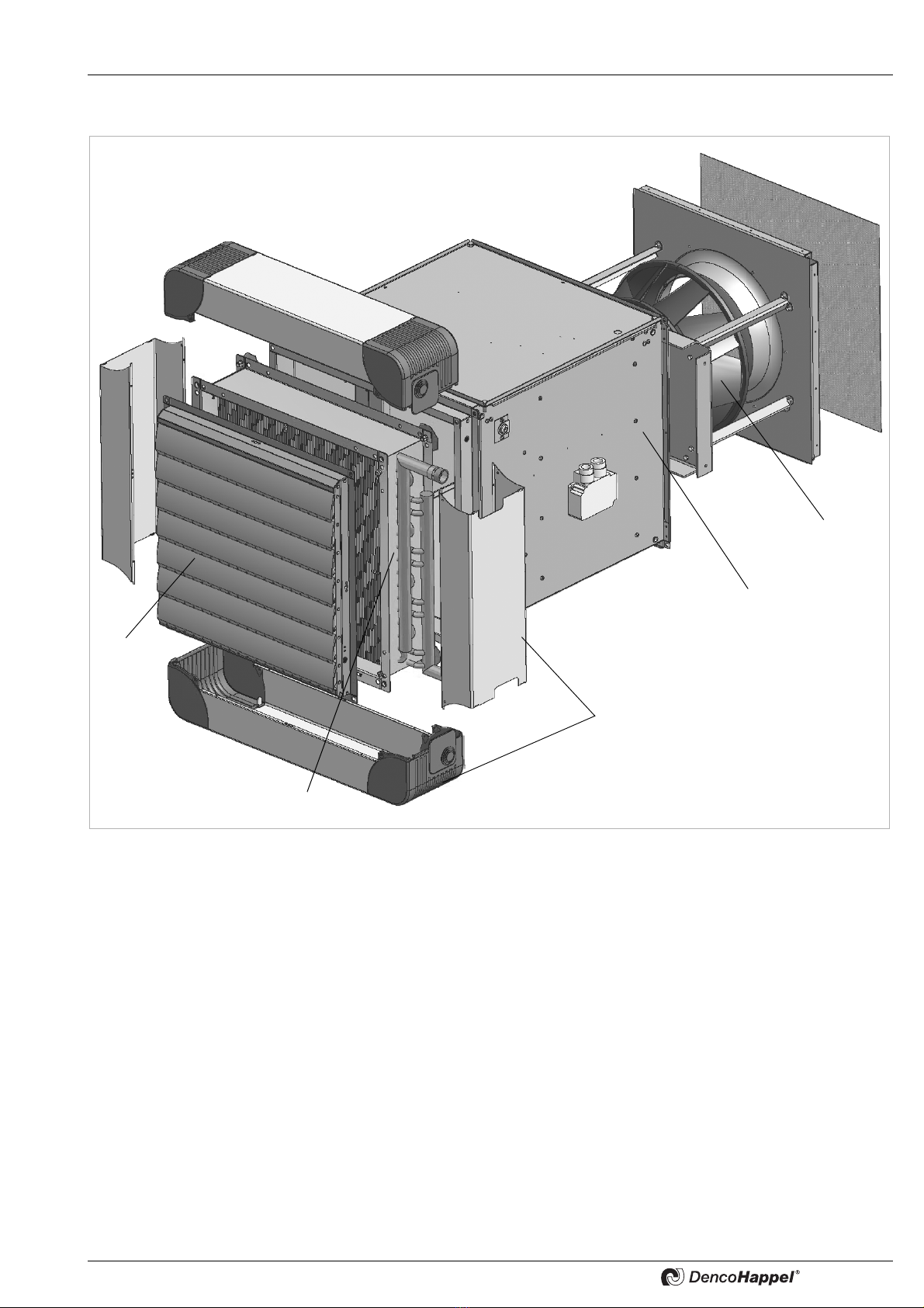
3 Technical Description and Scope of Supply
Fig. 3-1: Unit componets
1: Air discharge louvres
2: Heat exchanger
3: Fan module with inlet nozzle and terminal box
4: Fan with contact protection grille
5: Unit casing with plastic corners
1
2
3
4
5
Technical Description and Scope of Supply MultiMAXX HD
6PR-2007-0350-GB • Subject to modifications • R2-04/2016
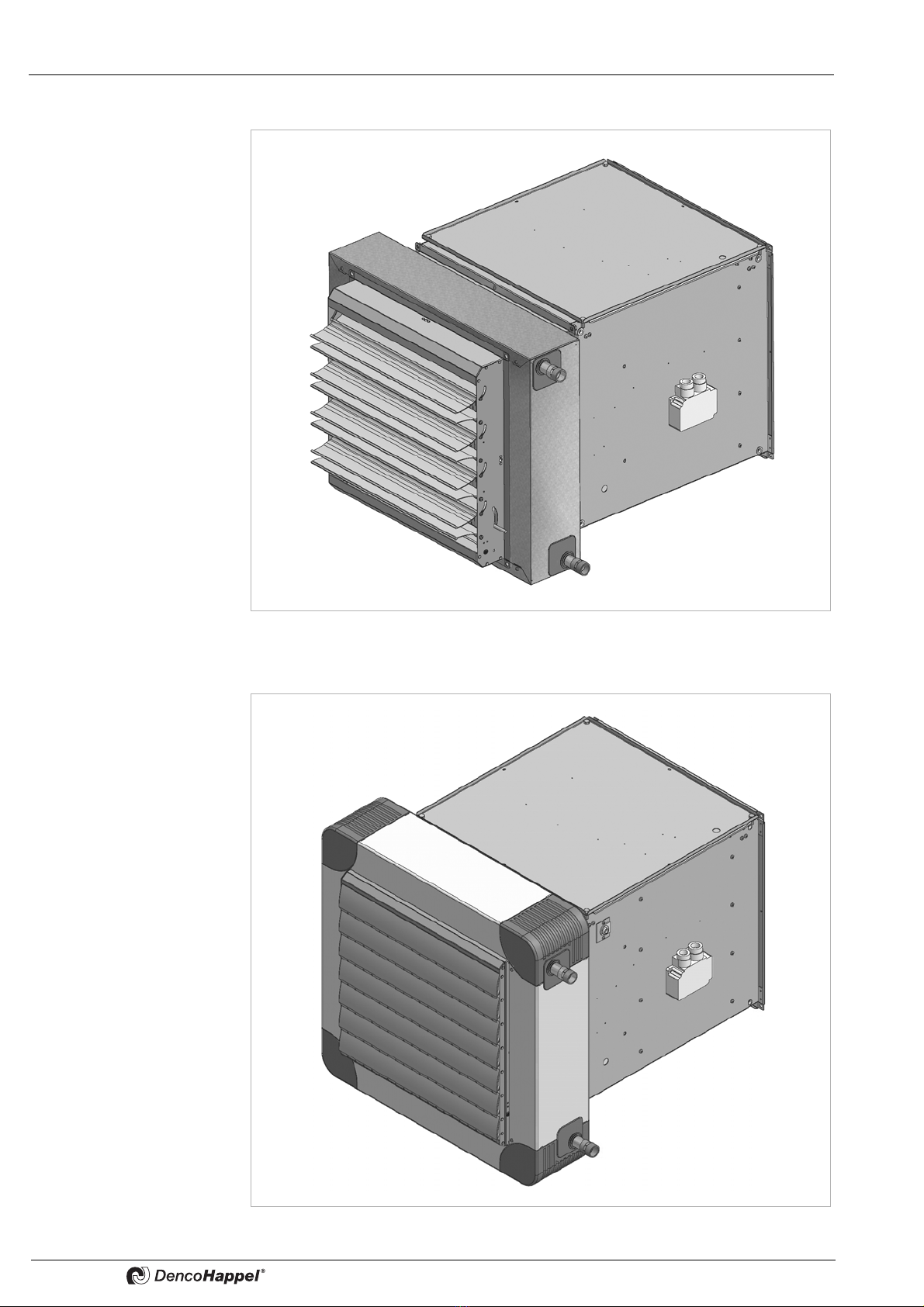
Unit in industrial casing
Unit in design / decorative casing
Fig. 3-2
Fig. 3-3

MultiMAXX HD Safety and User Information
PR-2007-0350-GB • Subject to modifications • R2-04/2016 7
4 Safety and User Information
The unit heaters MultiMAXX HD are developed and manufactured in
accordance with the state-of-the-art technological standards and established technical
safety codes and regulations. The unit heaters MultiMAXX HD comply with the EU
Machinery Safety Directive.
The unit heaters MultiMAXX are reliable and satisfy strict quality standards. This
product range combines advanced technology with a high level of user friendliness and
ease of maintenance. However, all unit heaters inevitably pose residual risks of injury
to the user or third parties or material damage to the unit or other objects. For this
reason, you should take into account and follow all safety instructions. Ignoring these
safety instructions is connected with risks to your health and safety, can lead to the
environmental damage and/or extensive material damage. Observing the safety
instructions in the operation manual will help you to avoid risks, ensure economical
operation of the unit and enjoy full benefits of the product. The safety aspects covered
by this chapter are valid for the entire operation manual.
4.1 Availability of the operation manual
The accompanying operation manual includes important information about the safe
and correct operation of the unit MultiMAXX HD.
This manual must always be available at the site where unit is in operation. Every per-
son working with or around the unit must read and apply the information contained in
the manual, paying particular attention to the safety instructions.
The operation manual is intended for use by fitting and installation companies, building
services engineers, technical personnel or trained persons as well as electrical and air-
conditioning engineering specialists.
4.2 Scope of the operation manual
This operation manual provides you with the necessary information about the following
subjects:
– Transportation and storage
– Assembly
– Installation
– Electrical connection
– Medium connection
– Commissioning and operation
– Maintenance
– Cleaning and disposal
4.3 Used symbols
The following symbols are used in this manual:
– This symbol is used to indicate normal lists.
•This symbol indicates instructions to follow.
9This symbol denotes the results of an action.
NOTE!
This symbol denotes additional information on use of the MultiMAXX HD.
RECYCLING!
This symbol indicates proper procedure for recycling of package material and disu-
sed unit components. These components need to be separated according to the
material type (e.g. metal, plastic etc.)
Safety and User Information MultiMAXX HD
8PR-2007-0350-GB • Subject to modifications • R2-04/2016
4.4 Labelling of safety instructions
PROTECTIVE SHOES!
This symbol indicated that you must wear protective shoes.
PROTECTIVE GLOVES!
This symbol indicated that you must wear protective gloves.
PERSONAL INJURY!
Here you will find special information as well as rules as restrictions for preventing
personal injury.
ELECTRICAL HAZARD!
This symbol indicates that there is a risk of electrical shock that can result in personal
injury including death and material damage.
HOT SURFACE HAZARD!
Here you can find special information as well as rules and restrictions for the
prevention of personal injuries due to hot surfaces.
DANGER – SHARP CUTTING EDGES!
Here you will find special information as well as rules and restrictions for the
prevention of personal injuries due to cutting on thin metal fins.
HIGH PRESSURE HAZARD.
Here you can find special information as well as rules and restrictions for the
prevention of personal injuries due to high pressure.
DANGER OF OVERHEAD LOADS!
This symbol indicates a hazardous location with a risk of personal injury
including death and material damage.
DANGER OF INFLAMMABLE MATERIALS
Here you can find special information as well as rules and restrictions for the
prevention of personal damage due to risk of fire.
ENVIRONMENTAL DAMAGE.
This symbol warns you against damage to the environment and turns your attention
you to all existing national environmental protection regulations.
DAMAGE TO THE UNIT!
Here you will find special information, rules and restrictions regarding the
prevention of damage to the MultiMAXX HD.
DANGER OF DAMAGE DUE TO STATIC DISCHARGE!
While carrying out connections or adjustments on the MultiMAXX make sure that you
discharge yourself statically before touchning PC boards and electrical
components.

MultiMAXX HD Safety and User Information
PR-2007-0350-GB • Subject to modifications • R2-04/2016 9
4.5 Safety-conscious working
To ensire your own safety consider the following safety instructions:
•Fluctuations and deviations of the supply voltage may not exceed the tolerance
limits specified in the technical data, otherwise functional failures and limit states /
excess pressures can not be excluded.
4.6 Proper use
The MultiMAXX HD unit heaters are exclusively designed for heating, ventilating and
filtering of indoor and outdoor air in industrial buildings, warehouses, sales and exhibi-
tion premises. Such accessories like filters, mixed air and air intake modules, suspen-
sion sets, switch units and control devices can be supplied.
Proper use also stipulates the observance of the operation manual as well as the
inspection and maintenance intervals specified by DencoHappel.
Any use other than that described above is considered improper. The manufacturer/
supplier is not liable for any damages arising from improper use. The user alone bears
the risk.
The following accident prevention regulations apply (VBG1, BGV A2 (previously:
VBG4), VBG7w, VBG9a) and generally recognized codes for machinery and principles
of engineering, particularly DIN VDE 0100, DIN VDE 0105.
4.7 Safety regulations and codes
When carrying out installation work, commissioning, maintenance and repair of the
MultiMAXX HD units all requirements of safety regulations and codes as well as gene-
rally established technical practices shall be considered.
4.8 Modifications and changes
You must not change, add to or modify the MultiMAXX HD in any way. Any changes or
modifications of the MultiMAXX HD will render the CE conformity and all warranty
claims null and void.
ELECTRICAL HAZARD!
All power supply connections must be switched off and checked to see if they
are voltage-free and then secured against unintentional switching on.
Earth and short-circuit them and cover over any neighbouring electrically
conducting parts or block them off. Failure to do so may lead to serious injury
or death.
DANGER OF DAMAGE DUE TO STATIC DISCHARGE!
While carrying out connections or adjustments on the MultiMAXX HD make sure that
you discharge yourself statically before touchning PC boards and electrical
components.
PERSONAL INJURY AND MATERIAL DAMAGE!
It is prohibited to operate the MultiMAXX HD units in following circumstances:
– in explosion risk areas;
– in rooms where conductive dusts are present;
– in rooms where strong electromagnetic fields are present;
– in rooms with aggressive environments that may attack plastics.

Safety and User Information MultiMAXX HD
10 PR-2007-0350-GB • Subject to modifications • R2-04/2016
4.9 Spare parts
You may use only original DencoHappel spare part since DencoHappel is not liable if
any third-party spare parts are used.
4.10 Disposal
Main and operating supply materials must be disposed of according to material type in
a safe and environmentally friendly manner. Also see „Disposal“ on page 47.
4.11 Personnel selection and qualification
Every person authorised to work on or around the MultiMAXX HD must have read this
entire operation manual and understood it completely – particularly the chapter on
safety. It is too late to do this during work.
All work must only be carried out by specialists with sufficient knowledge based on pro-
fessional training and experience in the following:
– Regulations concerning health and safety in the workplace
– Accident prevention regulations
– Directives and recognized codes of practice
All skilled persons must be able to assess what the work entrusted to them entails and
must be able to recognize and avoid any associated dangers.

MultiMAXX HD Technical Description
PR-2007-0350-GB • Subject to modifications • R2-04/2016 11
5 Technical Description
5.1 Functional description of the unit
The MultiMAXX HD unit heater consists of a heat exchanger and a fan with casing. The
casing is made of galvanized steel sheet and can be supplied in RAL colour according
to customer wishes. The air discharge opening can accommodate up to 13 different
types of discharge louvres. The diagonal fan is located in a fan casing on the rear side
of the heating unit. The protection grille prevents possible contact with the fan. The unit
rear side can be supplied with an attachment for mounting air intake accessories. The
fixing possibilities for suspending the unit using the ceiling or wall suspension are loca-
ted laterally on the fan box. The components made of non-ferrous metal and galvani-
zed connection parts are not protected by paint.

Technical Description MultiMAXX HD
12 PR-2007-0350-GB • Subject to modifications • R2-04/2016
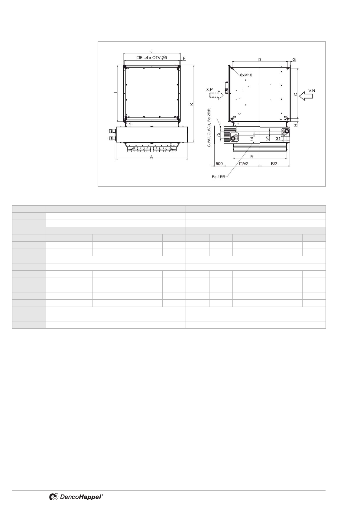
5.2 Unit dimensions and location of heat exchanger connecting spigots
5.2.1 Wall installation
Unit designation
Y, R
Fig. 5-1
Unit designation
U, M, W, O
Fig. 5-2
Space for installation and
maintenance
Space for installation and
maintenance
Size 1 2 3 4
A642 738 866 1026
B532 628 756 916
Model Model Model Model
Y, R U, M, W, O V, N, X, P Y, R U, M, W, O V, N, X, P Y, R U, M, W, O V, N, X, P Y, R U, M, W, O V, N, X, P
C473 427 427 569 523 523 697 651 651 857 811 811
D427 473 473 523 569 569 651 697 697 811 857 857
E470 566 694 854
F12 12 12 12
G3231–3231–3231–3231–
H31 32 34 31 32 34 31 32 34 31 32 34
I535 493 493 631 589 589 759 717 717 919 877 877
J493 547 494 589 643 590 717 771 718 877 931 878
K745 703 703 841 799 799 969 927 927 1129 1087 1087
L (Cu/Al, Cu/Cu) 399 447 511 591
L (Fe) 361 409 473 553
M 457 553 681 841
N300 300 400 400

MultiMAXX HD Technical Description
PR-2007-0350-GB • Subject to modifications • R2-04/2016 13
Unit designation
V, N, X, P
Fig. 5-3
Space for installation and
maintenance
Size 1 2 3 4
A642 738 866 1026
B532 628 756 916
Model Model Model Model
Y, R U, M, W, O V, N, X, P Y, R U, M, W, O V, N, X, P Y, R U, M, W, O V, N, X, P Y, R U, M, W, O V, N, X, P
C473 427 427 569 523 523 697 651 651 857 811 811
D427 473 473 523 569 569 651 697 697 811 857 857
E470 566 694 854
F12 12 12 12
G3231–3231–3231–3231–
H31 32 34 31 32 34 31 32 34 31 32 34
I535 493 493 631 589 589 759 717 717 919 877 877
J493 547 494 589 643 590 717 771 718 877 931 878
K745 703 703 841 799 799 969 927 927 1129 1087 1087
L (Cu/Al, Cu/Cu) 399 447 511 591
L (Fe) 361 409 473 553
M 457 553 681 841
N300 300 400 400

Technical Description MultiMAXX HD
14 PR-2007-0350-GB • Subject to modifications • R2-04/2016
Unit designation
Y, R
Fig. 5-4
Unit designation
V, N, X, P
Fig. 5-5
Space for installation and
maintenance
Space for installation and
maintenance
Size 1 2 3 4
A642 738 866 1026
B532 628 756 916
Model Model Model Model
Y, R V, N, X, P U, M, W, O Y, R V, N, X, P U, M, W, O Y, R V, N, X, P U, M, W, O Y, R V, N, X, P U, M, W, O
C473 427 427 569 523 523 697 651 651 857 811 811
D427 473 473 523 569 569 651 697 697 811 857 857
E470 566 694 854
F12 12 12 12
G32 31 – 32 31 – 32 31 – 32 31 –
H31 32 34 31 32 34 31 32 34 31 32 34
I535 493 493 631 589 589 759 717 717 919 877 877
J493 547 494 589 643 590 717 771 718 877 931 878
K745 703 703 841 799 799 969 927 927 1129 1087 1087
L361 409 473 553
N300 300 400 400
O41 45 49 55

MultiMAXX HD Technical Description
PR-2007-0350-GB • Subject to modifications • R2-04/2016 15
5.2.2 Ceiling installation
Unit designation
Y, R
Fig. 5-6
Unit designation
U, M, W, O
Fig. 5-7
Size 1 2 3 4
A642 738 866 1026
B532 628 756 916
Model Model Model Model
Y, R U, M, W, O V, N, X, P Y, R U, M, W, O V, N, X, P Y, R U, M, W, O V, N, X, P Y, R U, M, W, O V, N, X, P
C473 427 427 569 523 523 697 651 651 857 811 811
D427 473 473 523 569 569 651 697 697 811 857 857
E470 566 694 854
F12 12 12 12
G3231–3231–3231–3231–
H31 32 34 31 32 34 31 32 34 31 32 34
I535 493 493 631 589 589 759 717 717 919 877 877
J493 547 494 589 643 590 717 771 718 877 931 878
K745 703 703 841 799 799 969 927 927 1129 1087 1087
L (Cu/Al, Cu/Cu) 399 447 511 591
L (Fe) 361 409 473 553
M 457 553 681 841
Technical Description MultiMAXX HD
16 PR-2007-0350-GB • Subject to modifications • R2-04/2016
Unit designation
V, N, X, P
Fig. 5-8
Size 1 2 3 4
A642 738 866 1026
B532 628 756 916
Model Model Model Model
Y, R U, M, W, O V, N, X, P Y, R U, M, W, O V, N, X, P Y, R U, M, W, O V, N, X, P Y, R U, M, W, O V, N, X, P
C473 427 427 569 523 523 697 651 651 857 811 811
D427 473 473 523 569 569 651 697 697 811 857 857
E470 566 694 854
F12 12 12 12
G3231–3231–3231–3231–
H31 32 34 31 32 34 31 32 34 31 32 34
I535 493 493 631 589 589 759 717 717 919 877 877
J493 547 494 589 643 590 717 771 718 877 931 878
K745 703 703 841 799 799 969 927 927 1129 1087 1087
L (Cu/Al, Cu/Cu) 399 447 511 591
L (Fe) 361 409 473 553
M 457 553 681 841

MultiMAXX HD Technical Description
PR-2007-0350-GB • Subject to modifications • R2-04/2016 17
Unit designation
Y, R
Fig. 5-9
Unit designation
V, N, X, P
Fig. 5-10
Size 1234
A642 738 866 1026
B532 628 756 916
Model Model Model Model
Y, R V, N, X, P U, M, W, O Y, R V, N, X, P U, M, W, O Y, R V, N, X, P U, M, W, O Y, R V, N, X, P U, M, W, O
C473 427 427 569 523 523 697 651 651 857 811 811
D427 473 473 523 569 569 651 697 697 811 857 857
E470 566 694 854
F12 12 12 12
G32 31 – 32 31 – 32 31 – 32 31 –
H31 32 34 31 32 34 31 32 34 31 32 34
I535 493 493 631 589 589 759 717 717 919 877 877
J493 547 494 589 643 590 717 771 718 877 931 878
K745 703 703 841 799 799 969 927 927 1129 1087 1087
L361 409 473 553
O41 45 49 55
Technical Description MultiMAXX HD
18 PR-2007-0350-GB • Subject to modifications • R2-04/2016
Weight data are indicated for units including basic discharge and 3-speed fan motor.
5.3 Range of application
Unit heater Max. ambient temperature -20 °C to +40 °C
Power supply 3 x 400 V, or 1 x 230 V~ 50 Hz
Protection type IP 54
Power consumption See unit type plate
Heat exchanger
Cu/Al and Cu/Cu
Max. return temperature 70 °C
Max. operating temperature 130 °C
Max. medium pressure 1,6 MPa
Heat exchanger
Fe/FeZn
Max. operating temperature 180 °C
Max. medium pressure 1 row -1,6 MPa, 2 rows - 1,0 MPa
Heat exchanger
Size 1-3
Wall / ceiling units require valve regulation if the inlet temperature reaches +80 °C. The
valve shuts off the medium supply if the fan stops.
Heat exchanger
Size 4
Wall units require valve regulation if the inlet temperature reaches +130 °C (with ceiling
unit from +100 °C). The valve shuts off the medium supply if the fan stops.
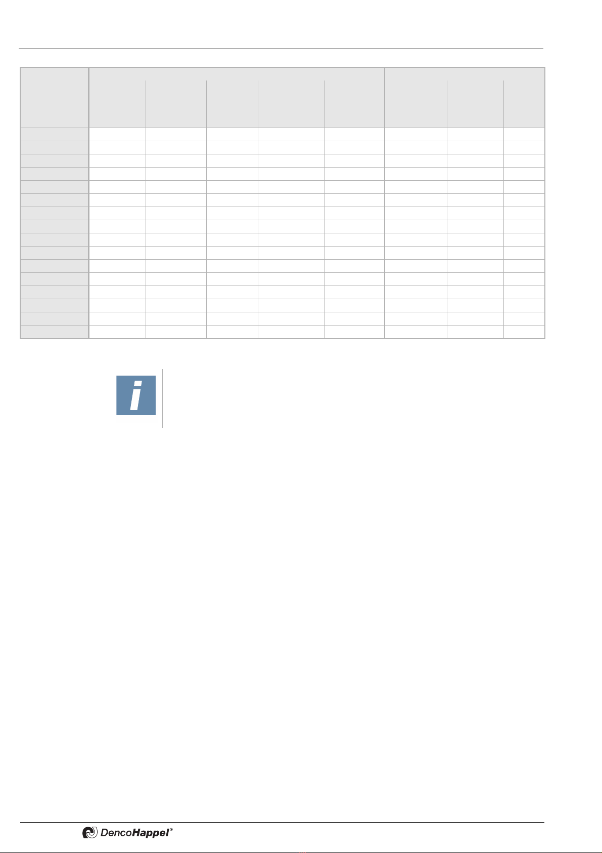
Size
Unit weight with heat exchanger Water content of heat exchanger
Cu/Al Cu/Cu Fe/Zn Fe/Zn, 6mm Fe/Fe steel Cu/Al and Fe/Zn Fe/Zn
circular pipe Cu/Cu
kg kg kg kg kg kg kg kg
(A) (C) (S) (T) (R) (A / C) (S / T) (R)
HD11 51 52 76 66 70 1,0 3,8 2,5
HD12 51 55 96 – 82 1,7 7,2 3,2
HD13 53 58 – – – 2,5 – –
HD14 55 61 – – – 3,2 – –
HD21 72 73 105 90 94 1,3 5,2 3,2
HD22 74 78 132 – 113 2,4 10,1 4,3
HD23 76 82 – – – 3,4 – –
HD24 78 86 – – – 4,3 – –
HD31 97 100 146 126 130 1,8 7,4 4,3
HD32 100 106 185 – 158 3,5 14,4 6,0
HD33 104 113 – – – 5,3 – –
HD34 107 119 – – – 6,3 – –
HD41 150 155 219 189 197 3,0 10,7 5,8
HD42 155 165 273 – 235 5,6 20,9 8,3
HD43 160 174 – – – 8,4 – –
HD44 166 184 – – – 9,9 – –
NOTE!
All other important information about unit capacity, weights, connections and sound
power can be found in the „Data and Facts MultiMAXX HD - New Generation“.

MultiMAXX HD Transportation and Storage
PR-2007-0350-GB • Subject to modifications • R2-04/2016 19
6 Transportation and Storage
6.1 Delivery
When transporting and storing the unit the manuafacturer’s instructions must be
adhered to (see specification on the packaging).
•After the MultiMAXX HD is delivered, check that the delivery is correct according to
the delivery note, and also check for completenes (see “Technical Description and
Scope of Supply” on page 5).
•It is necessary to take photographs of all visible transit damage.
6.2 Transport
•Only use lifting gear with sufficient load carrying capacity.
•Ropes/chains should not be knotted and/or be exposed to sharp edges.
•Never use damaged lifting equipment.
•Pay attention to equal weight distribution.
– For your own safety wear gloves and safety footwear when transporting the unit.
6.3 Storage
Protect the MultiMAXX HD unit from humidity and dirt. Store the unit on premises of
class IE12, in accordance with the requirements EN 60 721-3-1.
Permitted storage conditions / permitted air condition for units which have not yet been installed
Air temperature: -25 °C to +40 °C
Air humidity: up to 85 % (relative humidity with no condensation)
NOTE!
Missing parts or damage in transit can only be claimed with the transport insurance
if the damage has been confirmed by the carrier.
NOTE!
We recommend that you transport or store your MultiMAXX HD in its original pack-
aging. Remove the original packaging only before installation. The packaging must
be disposed of in accordance with the relevant regulations and must be kept out of
reach of children due to potential asscociated risks. Protect the unit from the build-
up of dust and dirt. Be aware of damage during storage until the unit is ready for com-
missioning.
DANGER DUE TO OVERHEAD LOADS.
Never stand beneath suspended loads.
PERSONAL INJURY!
Do not use damaged transport devices.
Use a fork lift truck only if the unit is located on a pallet.
DAMAGE TO THE UNIT!
When transporting / moving the unit never use heat exchanger connections and
spigots as this may result in damage to the MultiMAXX HD.
Installation MultiMAXX HD
20 PR-2007-0350-GB • Subject to modifications • R2-04/2016
7 Installation
7.1 Load-bearing capacity of the installation site
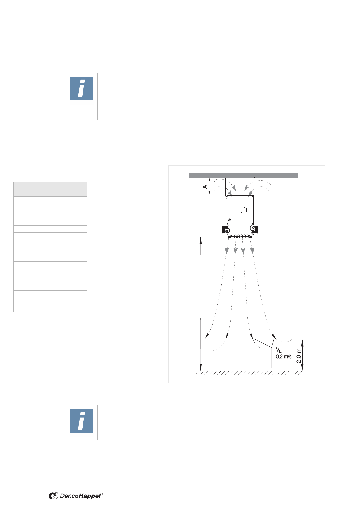
7.2 Ceiling installation
It is necessary to consider the suspension height, the distance between the units and
minimum distance from the ceiling.
Minimum distance from ceiling A (see Fig. 7-1)
It is necessary to keep the minimum distance to allow sufficient air intake and provide
sufficient access for maintenance.
NOTE ON UNIT ASSEMBLY AND INSTALLATION!
The assembly site must be vibration-free and suitable for permanently supporting the
weight of the unit heater. If necessary, the approval of a structural engineer or archi-
tect has to be received.
For fixing the unit there are two sets of 4 M10 nuts on the fan module - see
figure 5-1 and 5-10. The fixing material is enclosed with suspensions.
The suspension height of the unit is given in the table
The data in the chart are approximate and apply to the discharge temperuture if the
latter exceeds room temperature by 15 - 20 K
Fig. 7-1: Unit installation height with ceiling mounting
NOTE!
The maximum height of the unit ceiling installation varies depending on the
discharge temperature, lower speed and smaller air volume flow due to accessories.
Vertical configura-
tion of air louvres
Unit installation
height
Unit model Max. height
of installation (m)
HD11 11,5
HD12 9,8
HD13 9
HD14 7,5
HD21 14
HD22 13
HD23 12
HD24 11
HD31 13
HD32 12
HD33 11
HD34 10
HD41 14,5
HD42 13
HD43 12
HD44 11
Table of contents
Popular Heater manuals by other brands


Jaga
Jaga STRADA HYBRID MM Installation and operation manual

MILL
MILL Invisible & Glass Series Assembly and instruction manual

ELECTROTEK
ELECTROTEK ET-QH01 instruction manual

Clatronic
Clatronic HL 3378 instruction manual

RESTAURANTDOORS.COM
RESTAURANTDOORS.COM AIR-PRO AP-2-36-1-S S installation instructions

Toyoset
Toyoset Radiant 101 Operation and maintenance instructions


