Denlar D100 Manual

10 Denlar Dr., Chester, CT 06412 LAB-110073 Rev. 2.7 d
D1000 Installation and Service Manual 1
Home LAB-110073 Rev. 3
WARNING CAUTION
G
READ AND SAVE THESE INSTRUCTIONS
TO REDUCE THE RISK OF FIRE, ELECTRIC SHOCK, OR
INJURY TO PERSONS OBSERVE THE FOLLOWING:
1. Use this unit only in the manner intended by the
manufacturer. If you have any questions, contact the
manufacturer at the address or telephone number listed
on the front cover of this manual.
2. Before servicing or cleaning unit, put the unit into
Maintenance mode and disconnect power which will
prevent the unit from being powered ON accidentally.
When the Maintenance disconnect cannot be locked,
securely fasten a prominent warning device, such as a
tag, to the Maintenance panel.
3. Installation work and electrical wiring must be done by a
qualified person(s) in accordance with applicable codes
and standards, including fire-rated construction codes
and standards.
4. Sufficient air is needed for proper combustion and
exhausting of gases through the flue (chimney) of fuel
burning equipment to prevent back drafting. Follow the
HVAC equipment manufacturer’s guidelines and safety
standards such as those published by the National Fire
Protection Association (NFPA) and the American
Society of Heating, Refrigeration and Air Conditioning
Engineers (ASHRAE), and the local code authorities.
5. When cutting or drilling into wall or ceilings do not
damage electrical wiring and other hidden utilities.
6. To reduce the risk of fire or electric shock, do not use
this range hood with an additional speed control device,
unless provided by Denlar Fire Protection.
7. Ducted fans must always be vented outdoors.
8. To reduce the risk of fire, use only metal ductwork, or
follow local code.
9. Use with approved wiring only.
10. This unit must be grounded.
TO REDUCE THE RISK OF A RANGE TOP GREASE FIRE:
1. Never leave surface units unattended at high settings.
Boil-overs cause smoking and greasy spillovers that
may ignite. Heat oils slowly on low or medium settings.
2. Always turn fan ON when cooking at high heat or when
cooking flaming foods.
3. Clean ventilating fans and filters frequently. Grease
should not be allowed to accumulate on fan or filter.
4. Use proper pan size. Always use cookware appropriate
for the size of the surface element.
TO REDUCE THE RISK OF INJURY TO PERSONS
IN THE EVENT OF RANGE TOP GREASE FIRE
OBSERVE THE FOLLOWING: *
1. SMOTHER FLAMES with a close-fitting lid,
cookie sheet, or metal tray; then turn off the
burner. BE CAREFUL TO PREVENT BURNS. If
the flames do not go out immediately,
EVACUATE AND CALL THE FIRE
DEPARTMENT.
2. NEVER PICK UP A FLAMING PAN – You may
be burned.
3. DO NOT USE WATER, including wet dishcloths
or towels – violent steam explosion will result.
4. Use an extinguisher ONLY if:
A. You know you have a Class K extinguisher
and you already know how to operate it.
B. The fire is small and contained in the area
where it started.
C. The fire department is being called.
D. You can fight the fire with your back to an
exit.
*Based on “Kitchen Fire Safety Tips published by
NFPA
To Reduce General Risk
1. For general ventilating use only. Do not exhaust
hazardous or explosive materials and vapors.
2.
To avoid motor bearing damage and noisy and/or
unbalanced impellers, keep drywall debris,
construction dust, etc. way from hood.
3. For best capture of cooking impurities and
performance of fire extinguisher, your range hood
should be mounted so t
hat the bottom of the hood
is 24-36” above the cooking surface, depending
on model.
4. Please read Datasheets provided by Denlar Fire
Protection for further information and
requirements.
DISCLAIMER
:
DENLAR Fire Protection shall not be liable for errors contained in this Manual or for incidental,
consequential damages in connection with the furnishing, performance or use of this information. DENLAR Fire
Protection makes no warranty of any kind with regard to this information, including, but not limited to the implied
warranties of merchantability and fitness for a particular purpose.
D1000 Installation and Service Manual 2
Home LAB-110073 Rev. 3
TABLE OF CONTENTS
INSTALLATION:
1. System Anatomy
2. Sample Elevations
3. Preparing the Installation location
4. NFPA101 - Front/Rear Fan Installation
5. Range Element Disconnect Install
6. Handicap Accessible Controls
7. Installing the D1000
8. Fire Alarm System Connections
9. Manual Pull Station Installation
10. Ducting and Airflow
11. Electrical Schematic
12. Electrical Schematic Table
13. Maintenance Position and Maintenance
Mode
14. Tank and Link Replacement
15. Troubleshooting the D1000 System
16. Self-Monitoring System
17. Maintenance
18. Operating the Hood
19. After an Actuation
20. Common Parts List
Page 3
Page 4-5
Page 6-9
Page 10-11
Page 12-14
Page 15-16
Page 17
Page 18
Page 19-20
Page 21
Page 22
Page 23
Page 24
Page 25-26
Page 27
Page 24-25
Page 26-28
Page 29
Page 30-31
Page 32
D1000 Installation and Service Manual 3
Home LAB-110073 Rev. 3
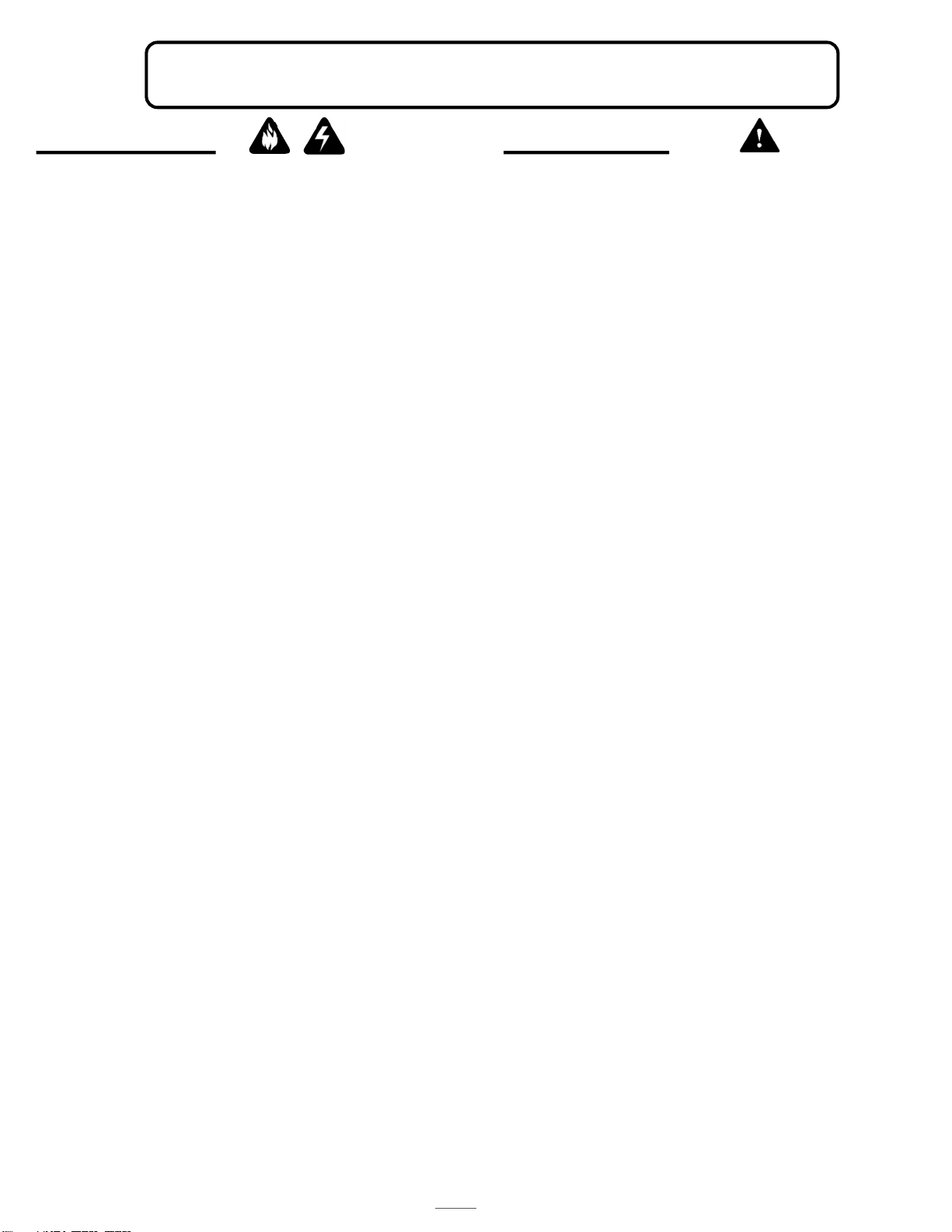
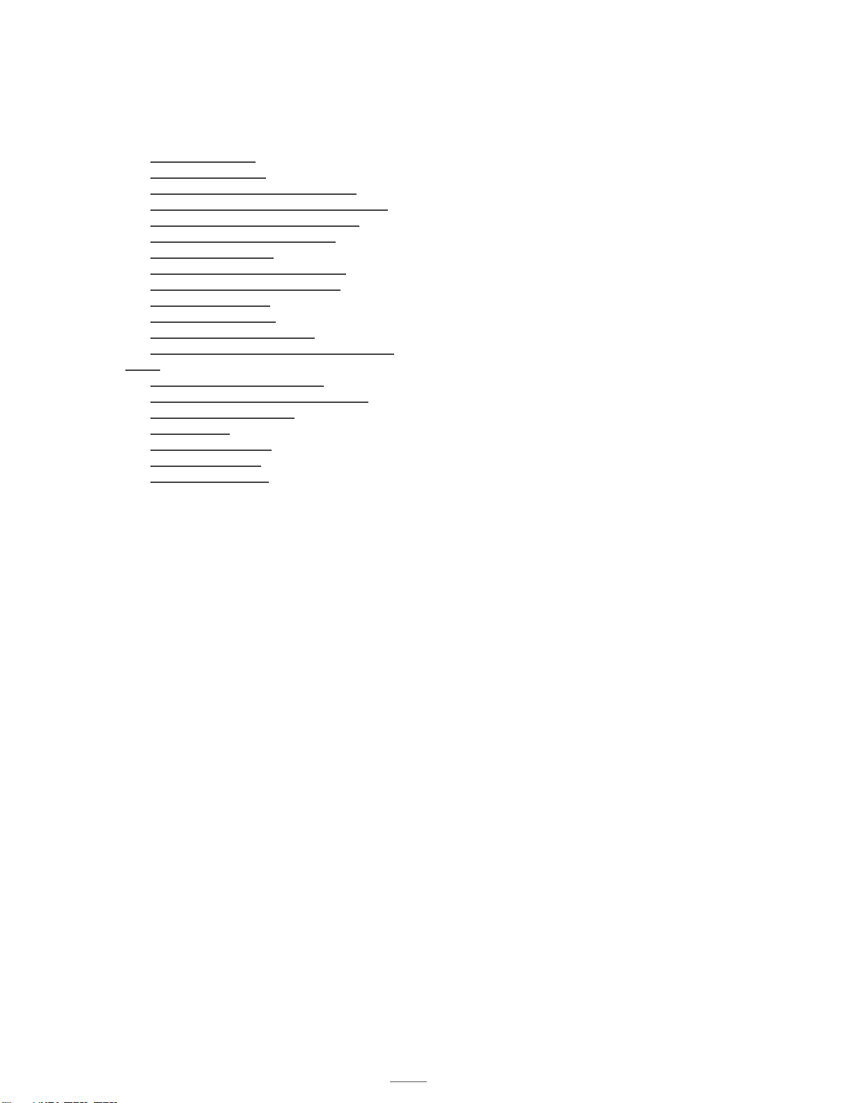
SYSTEM ANATOMY
Quarter Turn Screw (on
recirculating models) to remove
vent
Reset Switch
Thermostat
Thermostat
Thermostat
Filter
One 120 VAC 5-15P power cord input
14-2 MC Cable Output (with Black Tape marker)
Status LED
D1000 Installation and Service Manual 4
Home LAB-110073 Rev. 3
SAMPLE ELEVATIONS
D103X-F
D103X-R
D103X-F-NFPA
D103X-R-NFPA

D1000 Installation and Service Manual 5
Home LAB-110073 Rev. 3
SAMPLE ELEVATIONS
D103X-I-WM
D103X-I-WM-NFPA D103X-I-DF
D103X-I-DF-NFPA
D103X-I-RF
D103X-I-RF-NFPA

D1000 Installation and Service Manual 6
Home LAB-110073 Rev. 3
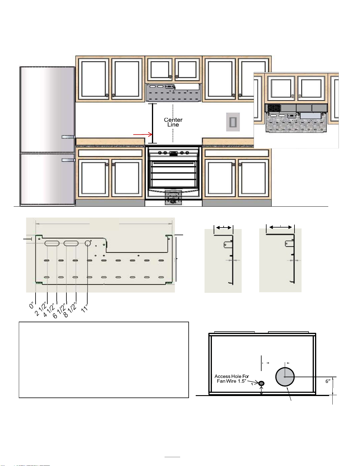
PREPARING THE INSTALL LOCATION
Note# 1: If cabinets are not present in the space, a Top Cover is required (option D1030 -TC I or F/R or D1036-TC I or F/R)
Note #2: Center the D1000 over the range. If the range is not in place, the center marking should be relative to its final
Position.
Note #3: Refer to the model specific engineered submittal sheet for the exact measurements which are not represented
here (available at denlarhoods.com)
Note #4: Refer to “Installing the D1000” (on page 17) for instructions on attaching the D1000 to the mounting
bracket
Note #5: Refer to option specific schematics for more details on how to connect them to the D1000
Note # 6: As indicated on page 7, allow for 4 5/8” between the top of the mounting bracket and the bottom of the
cabinet above. In order to allow the installation of the NFPA101 compliant version of the D1000-F/R, which uses an
additional Fan Box as shown attach the fan box to the bracket, and then proceed.
NOTE # 5 COMPONENTS
C
D
C
E
A
B
F
G
A. DENLAR D1000 (30” or 36”)
B. Range (for reference purposes (gas, electric or dual element, dual
receptacle)
C. Electric Power disconnect (shown)
D. Gas Power Disconnect (not shown)
E. The CLOCKBOX- range element lockout system (CLBX option) The
Touchscreen (E) is shown, the control module is not shown.
F. Handicap Accessible Control Box (ADA option)
G. Manual Pull Station (MPK option)
Note: The dual element disconnect (DED option) integrates both the
electric and gas power disconnect options.
View of Mounting Bracket Installed
D1000 Installation and Service Manual 7
Home LAB-110073 Rev. 3
(
Cabinet Bottom
View)
Access Hole for 7”
Duct
PREPARING THE INSTALL LOCATION
Min
Max
D1030
24"
30"
D1036
30"
36"
Installation Heights
4”
5 7/8”
Standard
Bracket
NFPA101
Bracket
Cabinet Front
B
B
A
A
B
C
D
28 5/8”
1/16”
1/16”
10 5/16””
1 5/8”
Mounting Bracket for D1000-F/R
(non-NFPA101)
Note # 6
Mounting Bracket
D1000 MOUNTING BRACKET
A. Center Notches
B. Critical Mounting Points (must be secured to suds or
dry wall hangers)
C. Primary Access Point for connections to hood
(options/accessories)
a. Supply lines run inside of the wall.
D. Additional Mounting Points
7 3/16”
4
”
C
D
NFPA101 “F” & “R” Rev
Install
See Pages 10 & 11 for
details
D1000 Installation and Service Manual 8
Home LAB-110073 Rev. 3
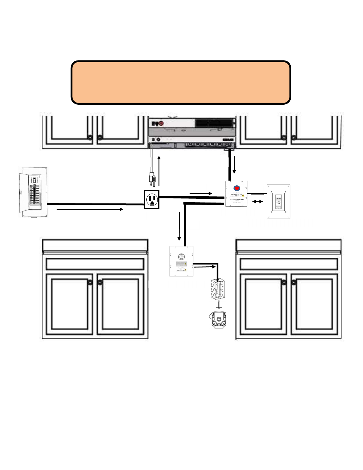
PREPARING THE INSTALL LOCATION
1
2
3
4
Electrical Disconnect
Clock Box
HMI / Touch Screen
5
5
-
15R
6
CAUTION: This should be performed by a licensed electrician. Installation
should be completed according to all applicable codes and regulations. Shut
off power at the main breaker to prevent electrical shock. Use Power Cord
(provided) or, replaced with wire specified by building codes.
7

D1000 Installation and Service Manual 9
Home LAB-110073 Rev. 3
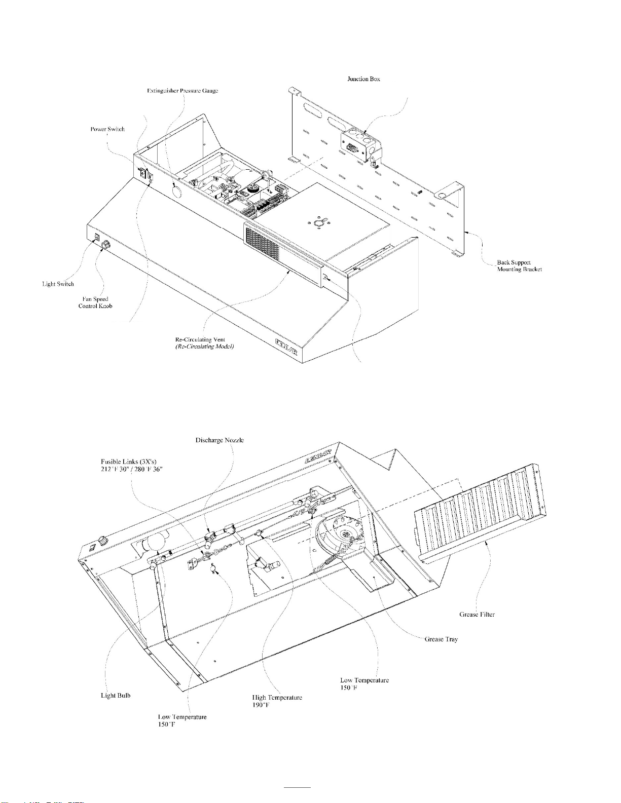
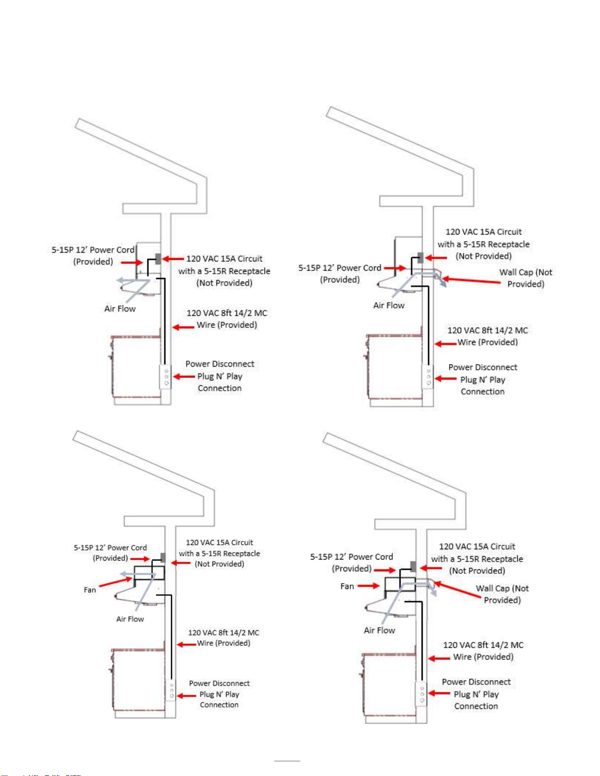
1. 120 VAC Input (not provided)
a. 120 VAC 15 Amp circuit provided by installer
b. Voltage supply from the Main Breaker Panel to the 5-15R Receptacle (not provided)
2. 120 VAC 15 Amp Plug Input to Hood (provided)
a. 12 Ft in length
b. Power Cord from the Hood and connects to the 5-15R Receptacle (not provided)
3. 120 VAC Output from Hood (provided)
a. 8 Ft in length
b. One 14/2 MC Wire
c. Cable from the Hood to the Clock Box (if applicable) or the Power Source Disconnect for the Range
(Gas or Electric)
4. 120 VAC Input (not provided)
a. 120 VAC 15 Amp circuit provided by installer
b. Voltage supply from the Main Breaker Panel to Clock Box (not provided)
5. 120 VAC Input to Power Source Disconnect for the Range (not provided)
a. 120 VAC Provided by installer
6. 5 VDC Input / Output Communication cable encased in 16 mm ENT Flexible Conduit (provided)
a. 25 Ft in length
b. One communication cable
c. Connects to the Clock Box PLC and HMI / Touch Screen
7. Power Source Disconnect (not provided)
a. 120 VAC jumper between Electric and Gas Disconnects
D1000 Installation and Service Manual 10
Home LAB-110073 Rev. 3
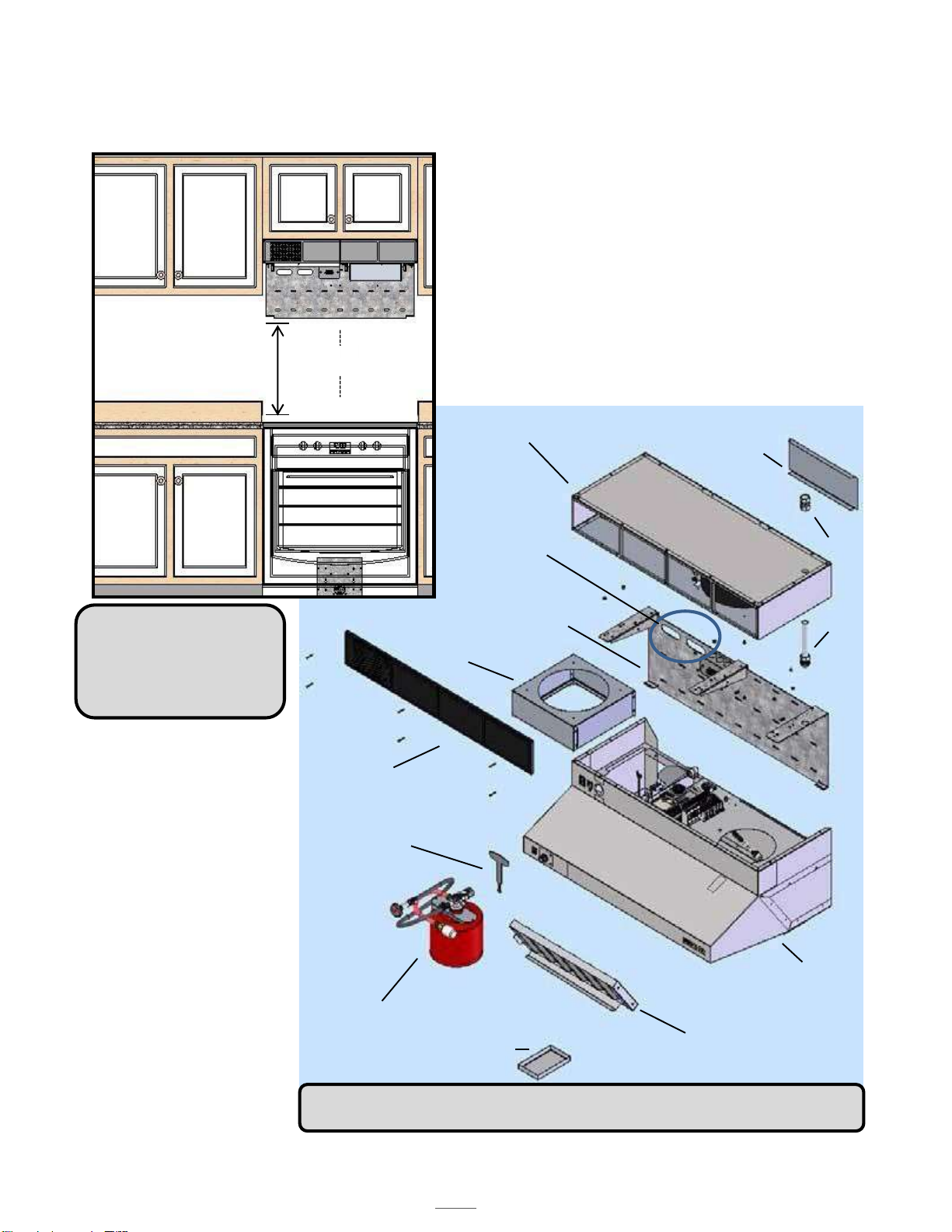
NFPA101 FRONT/REAR (F/R) DISCHARGE INSTALLATION
The NFPA101 compliant
calibration of the DENLAR
D1000 was engineered to comply with the
requirements of the NFPA Life Safety Code, related
to residential cooking appliances used in non-
production cooking environments. Due to the
specific performance requirements in the code, the
NFPA101 version of the D1000 differs slightly from
the standard calibration. Refer to this section for
NFPA101 Front/Rear version-specific information.
Fan Box
(NFPA 101)
Duct Access (Remove plate for rear
exhaust configuration)
MPK
Min
Max
D1030
24"
30"
D1036
30"
36"
Installation Heights
Mounting Bracket
Duct Collar
Front Grille
(F configuration)
Safety Key
MPK
Extinguisher Tank
D1000 Hood
Stainless Steel Grease Filter
Stainless Steel Grease Tray
The NFPA101 versions of
the D1000-F and D1000-
R are identical barring the
rear’s (R) need for
ducting to pass through
the exterior wall. Where
the (R) expels vapor
through the rear of the
hood the fascia of the fan
box is a continuous
stainless steel cover.
NOTE: The NFPA101
versions of the D1000-D
does not change the hood
as the fans are installed
remotely.
NOTE: The NFPA101 recirculating option is not approved for use in installations Group
I
-
1 and I
-
2 occupancies per section 505.3 of the 2018 version of the
IMC
.
Opening ports
Input/output supply
Wires running
inside of wall.
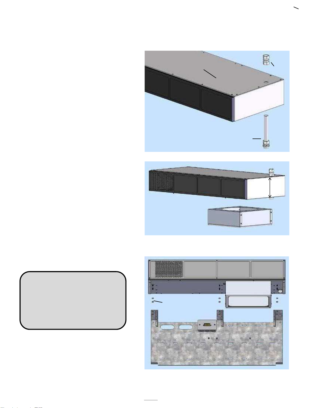
D1000 Installation and Service Manual 11
Home LAB-110073 Rev. 3
If installing under cabinets, keeping the fan
box flush to the underside will guarantee
correct spacing. Otherwise, center and
mark the installation area according to the
mounting bracket prior to hanging. Keep
4.5” below the underside of the cabinet to
allow the fan bracket to be installed later.
1. Insert/attach the top portion of the
MPK conduit through the fan box.
2. Attach the fan box to the mounting
bracket with included 8-32 nuts,
then complete the installation on
the MPK conduit and top/bottom
unions.
The fan box is 4.5” tall. If prepping a space
for install, 4.5” must be left between the
top of the mounting bracket and the
bottom of the cabinet.
The additional height of the unit should not
result in reduced range clearance.
Cabinets should be installed approximately
5” higher to accommodate the additional
size of the NFPA101 fan box assembly.
NFPA101 FRONT/REAR DISCHARGE INSTALLATION
Fan Box
Conduit
Coupler
Fitting
MPK
Conduit
4 ½”
NOTE: The NFPA LSC (101) requires
500CFM of airflow in a 300A hood and
suppression system. This amount of
airflow, through a recirculating hood, will
create inefficiencies within the system
resulting in additional noise production.
Fan Box
8-32 Nuts
Mounting Bracket
D1000 Installation and Service Manual 12
Home LAB-110073 Rev. 3
RANGE ELEMENT DISCONNECT INSTALLATION
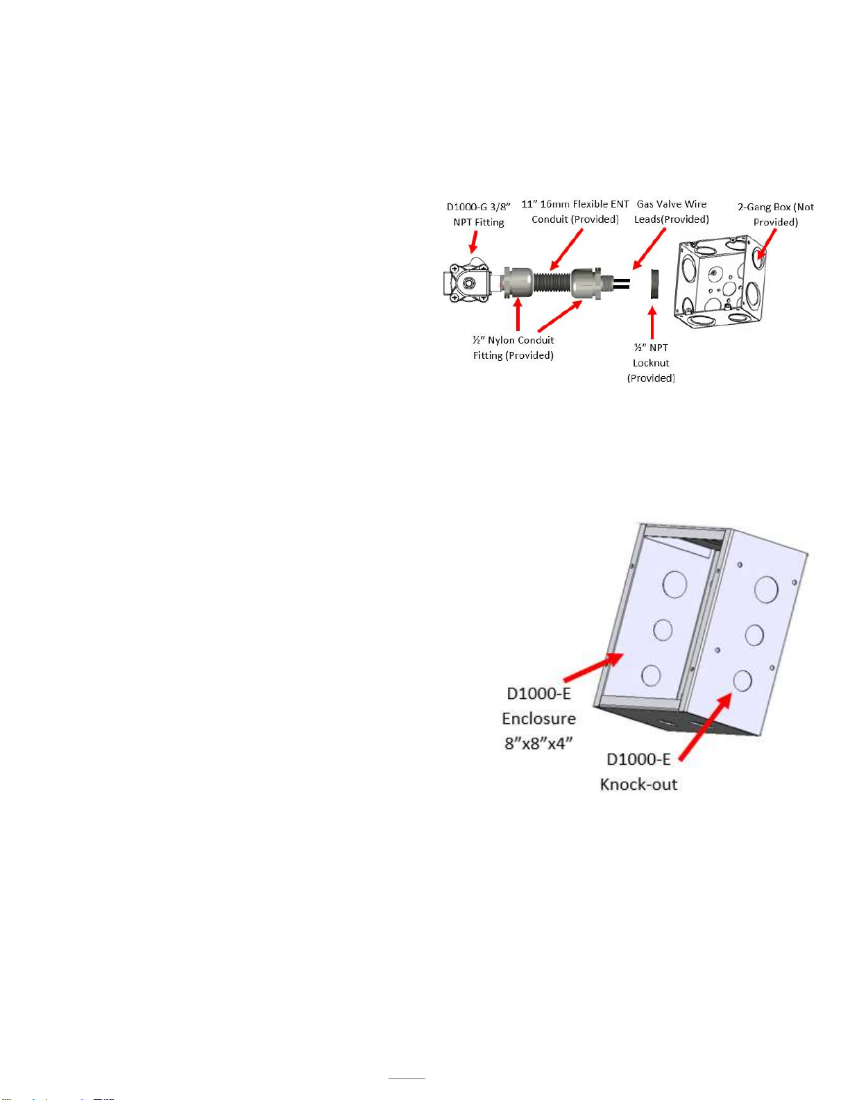
D1000-G Installation
1. Secure the gas line input and output to the D1000-G.
The fittings are 3/8” NPT. Note the direction of the flow,
there is an arrow on the bottom of the D1000-G.
2. The D1000-G has an 11” 16mm Flexible ENT Conduit
with the wire leads inside. Install the 11” 16mm Flexible
ENT Conduit attached with a plug into the 2-Gang Box.
Secure the Box.
3. Run the120 VAC 8 ft 14/2 MC Wire (Provided) from the
hood’s junction box location found on the mounting
bracket, to the power disconnect location.
4. Install the cover for the 2-Gang Box.
Note: The Coil voltage cannot be used to power the
electronics in the range (clock, ignitors, etc.). Doing this voids the warranty and ETL listing of the Hood, in addition to blowing
the fuses and damaging the PLC.
D1000-E Installation
1. Cut a hole in the drywall for the D1000-E Enclosure; refer to the
specification sheets for the dimensions. Be sure to note the 1 ¼”
overhang on both sides of the face plate. The cutout opening
should be about 8 3/8”. The power disconnect has been designed
to fit a standard 2” x 4” framed wall.
5. Run the120 VAC 8 ft 14/2 MC Wire (Provided) from the hood’s
junction box location found on the mounting bracket, to the power
disconnect location.
2. Run 120 VAC 15 – 20 Amps or 220 VAC 20 – 50 Amps from Main
Breaker Panel (Not Provided) to the contactor. This will provide
power to the receptacle.
3. Secure the face plate to the power disconnect.
D1000 Installation and Service Manual 13
Home LAB-110073 Rev. 3
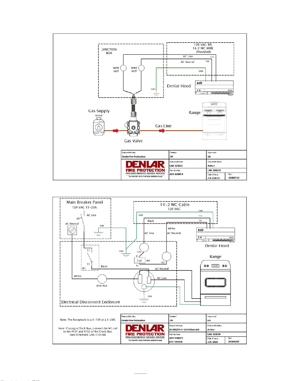
D1000-G Schematic
D1000-E-120 Schematic
D1000 Installation and Service Manual 14
Home LAB-110073 Rev. 3
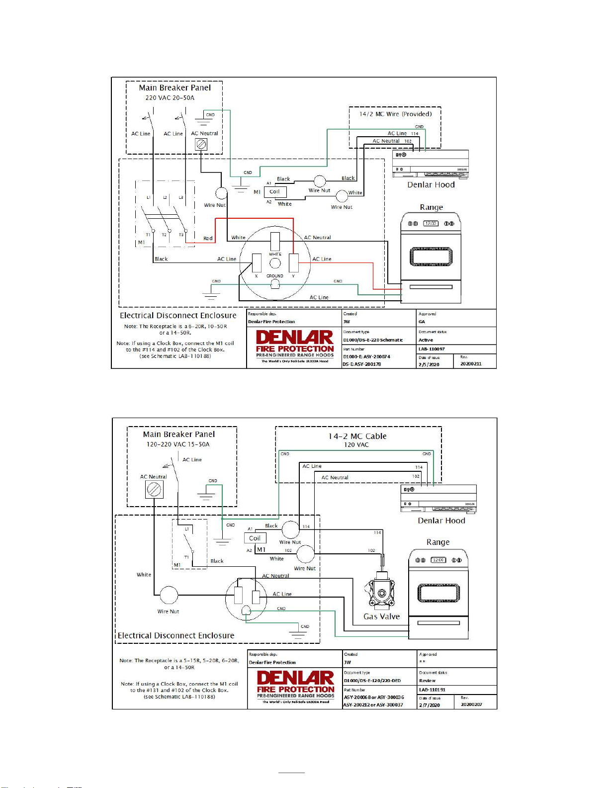
D1000-E-220 Schematic
D1000-DED Schematic

D1000 Installation and Service Manual 15
Home LAB-110073 Rev. 3
HANDICAP ACCESSIBLE CONTROLS (ADA)
COMPONENTS
ADA Wire Harness Assembly
o (2) Toggle Switches (white)
o (15’) Plenum Cable Encased in 16mm ENT Flexible Conduit
o (1) Eight Position Male Connector (Plug-N-Play)
o (1) 2-Gang White Switch Cover
o (2) Mounting Brackets
PREPARATION
Turn OFF the main 110-120 VAC power (at the panel) to the Hood or
unplug the Six Position connector at the Handy Box (Hood) labeled Power
Input/Output. Remove the ADA Wire Harness Assembly from the packing.
INSTALLATION
1. Unscrew the two switches from the Metal 2-Gang Enclosure.
2. Mount the Metal 2-Gang Enclosure to the desired wall using the mounting
brackets in accordance with local building codes and electrical codes.
3. Screw the two switches back to the Metal 2-Gang Enclosure.
4. Install the 2-Gang White Switch Plate on the Metal 2-Gang Enclosure.
5. Run and secure the Plenum Cable Encased in 16mm ENT Flexible
Conduit. Plug the Eight-Position male and female connectors together,
labeled ADA Plug.
6. Ensure electrical connections are tight.
7. Turn the power on for the Hood.
8. The switch on the left of the Metal 2-Gang Enclosure with the Red and
White wires connected to it is for the fan function. Turning on this switch,
enables the fan to run at High Speed only. There is no speed control with
this switch.
Note: In order to turn the fan OFF, both the ADA toggle
switch and the speed control at the hood need to be OFF.
9. The switch on the right of the Metal 2-Gang Enclosure with Black and
White wires connected to it is for the light function.
Note: In order to the turn the light OFF, both the ADA toggle
switch and the light switch at the hood need to be OFF.
Handicap Accessible
Controls

D1000 Installation and Service Manual 16
Home LAB-110073 Rev. 3
HANDICAP ACCESSIBLE CONTROLS
D1000-ADA Schematic

D1000 Installation and Service Manual 17
Home LAB-110073 Rev. 3
INSTALLING THE D1000
1. Line unit up to the secured D1000 mounting
bracket and seat lower tabs into slots in the back of
the hood.
3. Connect the power to the junction box.
4. On the tank, remove the safety pin-identified
with the yellow flag “caution” from the trigger
on top of the extinguisher bottle.
Safety Pin
5. Remove the safety key from the actuator arm by
rotating and lifting the key straight upwards.
THE SYSTEM WILL NOT ACTUATE
WITHOUT COMPLETING STEPS 4 & 5.
Safety Pin
NOTE: The system is
armed after steps 4
& 5 are completed.
NOTE: Install the MPK prior to arming the system.
6. Tilt the D1000 hood towards wall and thread
the three thumb nuts to the bolts in the back-
support mounting bracket. See page 24 for
location of thumb nuts.
2. While holding the unit up, hook cable to the
chain link on the mounting bracket and screw
the nut to close the link. The hood is now in
maintenance position.
Yellow Caution Flag
Safety Key
D1000 Installation and Service Manual 18
Home LAB-110073 Rev. 3
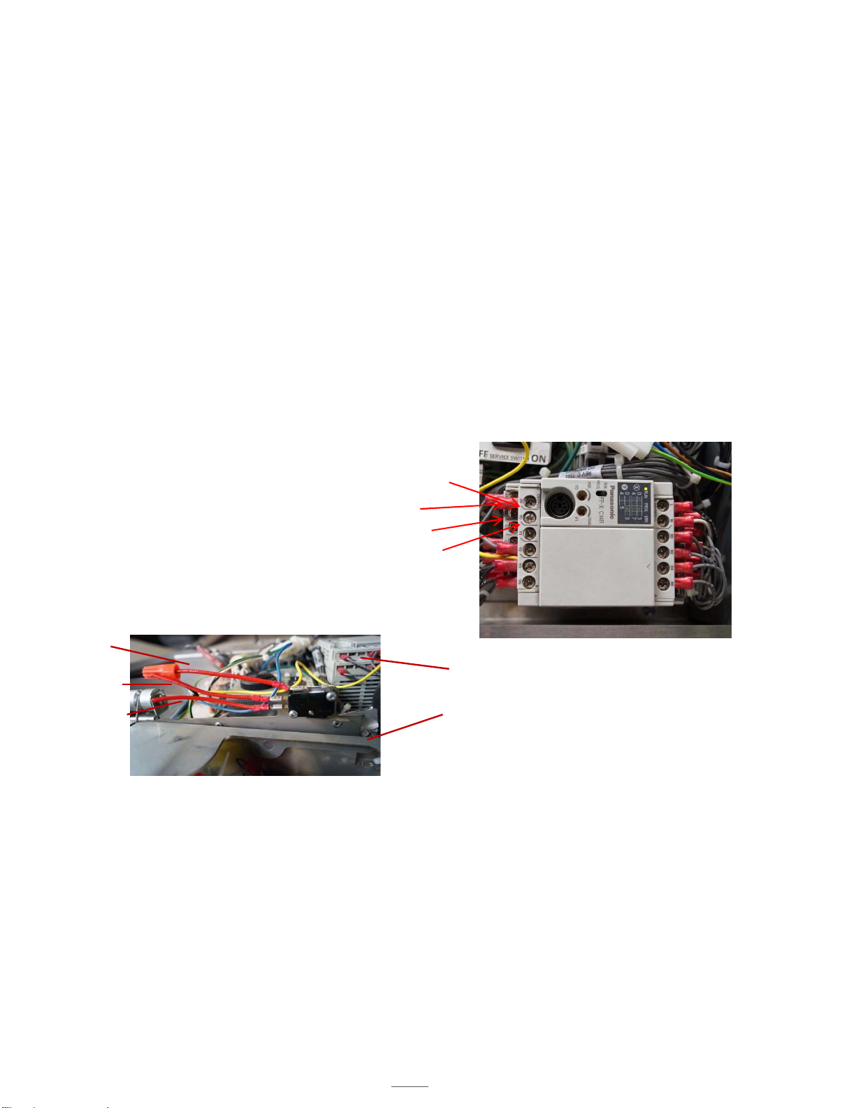
FIRE ALARM CONNECTIONS
The D1000 has three fire alarm connections (discrete switches), each independent from each other. Two are controlled by
the PLC and one is mechanical.
A connection is made to one output (Y#) and one common (C#) at the PLC. The output labeled YO is triggered by
a fault from Hi-Temp, 190F, pressure switch or hose switch. A buzzer in the unit will sound and the power
disconnect will turn off.
Output, Y1, is triggered by a high temperature switch, 190F, and a low-pressure fault in the extinguisher tank
(the fire suppressant has discharged). When there is a fault, a buzzer in the unit will sound and the power
disconnect will turn off.
PLC CONTROLLED ALARMS-REQUIRE POWER TO THE HOOD
Local Alarm Connection: Connect to output Y0 and common C0
Remote Alarm Connection: Connect to output Y1 and common C1
To connect to the alarms, it is recommended that you use a 3.22mm spade fork connector (not supplied), however a
stripped wire is acceptable.
Either one of the connections may be used depending on the needs of the job site.
Connecting the alarm system in configurations described above results in a normally open connection.
Common
Normally Open
Normally Closed
Fire Alarm Switch
Figure 14.2
MECHANICAL SWITCH – NOT POWERED
This connection does not require power to be supplied to the hood in order to function. The alarm switch is located above
the actuator arm, next to the PLC assembly. The alarm switch is tripped when the actuator arm is released.
Wire the alarm to the common connector and normally open, or normally closed connection as shown, depending
on what the on-site alarm requires.
Actuator Arm
PLC Assembly
Y0
C0
C1
Y1
D1000 Installation and Service Manual 19
Home LAB-110073 Rev. 3
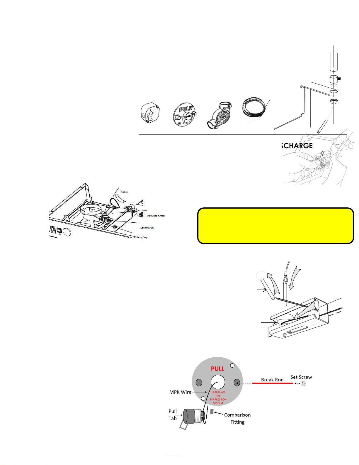
MANUAL PULL STATION (MPK) INSTALLATION
STEP 1: INSTALLING CONDUIT
Mount the pull box in an appropriate location according to local building codes. The MPK supplied with
twenty-five feet of wire rope cable and three elbow pulleys as our listing requires.
Install ½” conduit (not provided) between the unit and the pull box, using the pulleys as
needed.
Pull the wire rope cable through the conduit and allow 8-12” of slack to be left at the hood unit
end.
Be sure to abide by all local building and fire codes when installing the conduit.
STEP 2: PLACE UNIT IN MAINTENANCE MODE TO HELP PREVENT ACCIDENTAL DISCHARGE
Ensure that the unit is in Maintenance mode (see Page 20).
CHECK THE FOLLOWING:
The safety pin is in its slot at the top of the extinguisher tank. See figure 14.3 Tank Safety
Pin
The safety key is in its slot in the actuator arm.
STEP 3: INSTALL ACTUATION CABLE AND PIN TO CLEVIS
Thread the actuation cable through the conduit, with the pin reaching the unit.
Remove the grease baffle.
There is a turnbuckle attached to the link cable, located in the plenum. Turn the
turnbuckle to release tension on the link cable
In the upper corner, locate the two pulleys (see Figure 14.4 Pulley-Unit)
Hold the rear-most pulley in place.
From the top of the unit, replace the existing clevis pin with the one on the wire rope cable.
Push the pin through the pulley until it clicks in place.
Re-attach the actuation cable onto the actuator arm.
STEP 4: INSTALL WIRE ROPE CABLE TO PULL FACE
While the unit is still in Maintenance position, attach the wire rope cable to the pull
face by crimping a sleeve in the wire rope cable through the back side of the handle.
Ensure the wire rope cable is securely crimped
to withstand at least 40 lbs. of pull force.
Leave no more than 12” of slack in the line on
the pull face end but maintain 8-12” of slack.
Remove the MPK handle by loosening the set
screw in one of the studs and sliding the red
plastic rod out.
Attach the pull face to the pull box that is
already mounted to the wall, collecting any
slack into the pull box.
Pull Box (X1) Pull Face (X1)
Elbow Pulley (X3)
Wire Rope Cable
crimped with sleeve
and Pin (25ft)
Figure 14.3
Tank Safety Pin
WARNING: You must allow for 8-12” of slack in the
wire rope cable to sit at the pull face. Failure to do so
will cause the unit to discharge the next time the unit is
lowered into its service position.
Conduit Attachment
mounting bracket
Figure 14.4
Pulley-Unit
Clevis Pin
Rear most
Pulley
Table of contents
Other Denlar Ventilation Hood manuals


