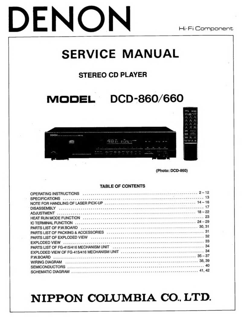
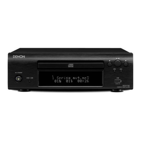
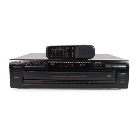
Denon DCD-3520 User manual

DENON
SERVICE
MANUAL
Hi-Fi
Component
4
STEREO
CD
PLAYER
MODEL
DCD-3520
PARTS
LIST
OF
FG-621MECHA
UNIT...
0...
ee
40
PWeBOARD?:
pinto
Sota
ado
dewstal
wale
giatkot
nae
oe
ata
d
bod
ds
Beet
ee
ate
aed
41
~
43
WIRING
DIAGRAM
...
20.0
1.
ce
eect
nes
44
SEMICONDUCTORS»
sc.0
6
bee
8
ae
ch
Aken
ed
oe
G
Aas
Sida
a
alee
4
45,
46
SCHEMATIC
DIAGRAM
..
1...
ee
eee
eae
47,
48
NIPPON
COLUMBIA
CO.
LTD.

IMPORTANT
TO
SAFETY
WARNING:
TO
PREVENT
FIRE
OR
SHOCK
HAZARD,
DO
NOT
EXPOSE
THIS
APPLIANCE
TO
RAIN
OR
MOISTURE.
CAUTION:
1.
Handle
the
power
supply
cord
carefully
Do
not
damage
or
deform
the
power
supply
cord.
If
it
is
damaged
or
deformed,
it
may
cause
electric
shock
or
malfunction
when
used.
When
removing
it
from
wail
outlet,
be
sure
to
remove
by
holding
the
plug
attachment
and
not
by
pulling
the
cord.
2.
Do
not
open
the
top
cover
In
order
to
prevent
electric
shock,
do
not
open
the
top
cover.
lf
problems
occur,
contact
your
DENON
DEALER.
3.
Do
not
place
anything
inside
Do
not
place
metal
objects
or
spill
liquid
inside
the
CD
player.
Electric
shock
or
malfunction
may
result.
Please,
record
and
retain
the
Model
name
and
serial
number
of
your
set
shown
on
the
rating
label.
Model
No.
DCD-3520
Serial
No.
RISK
OF
ELECTRIC
SHOCK
O00
NOT
OPEN
CAUTION:
TO
REDUCE
THE
RISK
OF
ELECTRIC
SHOCK,
DO
NOT
REMOVE
COVER
(OR
BACK).
NO
USER
SERVICEABLE
PARTS
INSIDE.
REFER
SERVICING
TO
QUALIFIED
SERVICE
PERSONNEL.
The
lightning
flash
with
arrowhead
symbol!
within
an
equilateral
triangle
is
intended
to
alert
the
user
of
the
presence
of
uninsulated
“dangerous
voltage”
within
the
product's
enclosure
that
may
be
of
sufficient
magnitude
to
constitute
a
risk
of
electric
shock
to
persons.
The
exclamation
point
within
an
equilateral
triangle
is
intended
to
alert
the
user
of
the
presence
of
A
important
operating
and
maintenance
(servicing)
instruction
in
the
literature
accompanying
the
ap-
pliance.
IMPORTANT
(BRITISH
MODEL
ONLY)
The
wires
in
this
mains
lead
are
coloured
in
accordance
with
the
following
code:
Blue:
Neutral
Brown:
Live
The
colours
of
the
wires
in
the
mains
lead
of
this
apparatus
may
not
correspond
with
the
coloured
markings
identifying
the
terminals
in
your
plug
proceed
as
follows.
The
wire
which
is
coloured
blue
must
be
connected
to
the
terminal
which
is
marked
with
the
letter
N
or
coloured
black.
The
wire
which
is
coloured
brown
must
be
connected
to
the
terminal
which
is
marked
with
the
letter
L
or
coloured
red.
NOTE:
This
CD
player
uses
the
semiconductor
laser.
To
allow
you
to
enjoy
music
at
a
stable
operation,
it
is
recommended
to
use
this
in
a
room
nf
§°C
-
35°C.
LABELS
-
CAUTION
DEWON
AMERICA
INC
CERTIFICATION
122
MEW
ROAD,
THIS
PRODUCT
COMPLIES
WITH
DBRS
RULES
PARSIPPANY,
W
).
DICER
SUBCHAPTER
|
APPLICABLE
AT
DATE
OF
02054
USA
CAUTION:
q
USE
OF
CONTROLS
OR
ADJUSTMENTS
OR
REFORMANCE
OF
PROCE-
DURES
OTHER
THAN
THOSE
SPECIFIED
HEREIN
MAY
RESULT
IN
HAZARDOUS
RADIATION
EXPOSURE.
THE
COMPACT
DISC
PLAYER
SHOULD
NOT
BE
ADJUSTED
OR
REPAIRED
BY
ANYONE
EXCEPT
PROPERLY
QUALIFIED
SERVICE
PERSONNEL.
NOTE:
This
unit
may
cause
interference
to
radio
and
television
reception
if
you
do
not
operate
it
in
strict
accordance
with
this
OPERATING
q
INSTRUCTIONS.
This
unit
complies
with
Class
B
computing
device
rules
in
accord-
ance
with
the
specifications
in
Sub-part
J
or
Part
15
of
the
FCC
Rules,
which
are
designed
to
provide
reasonable
protection
against
such
interference
in
a
residential
installation.
If
the
unit
does
cause
interference
to
any
radio
or
television
reception,
try
to
reduce
it
by
one
or
more
of
the
following
means:
a}
Turn
the
other
unit
to
improve
reception
b)
Move
this
unit
c)
Move
this
unit
away
from
others
4
d)
Plug
this
unit
respectively
into
a
different
AC
outlet
*
This
is
note
in
accordance
with
Section
15.838
of
the
FCC
Rules.
VAROITUS:
|SUOJAKOTELOA
El
SAA
AVATA.
LAITE
SISALTAA
LASERDIODIN,
JOKA
LAHETTAA
NAKYMATONTA
SILMILLE
VARRALLISTA
LASERSATEILYA.
ADVARSEL:
USYNLIG
LASERSTRALING
VED
ABNING
NAR
SIKKERHEDSAFBRYDERE
ER
UDE
AF
FUNKTION.
UNDGA
UDSAETTELSE
FOR
STRALING.
VARNING:
OSYNLIG
LASERSTRALNING
VID
AVLAGSNANDE
AV
APPARATENS
HOLJE.
UNDVIK
EXPONERING
AV
LASERSTRALNING.
“CLASS
1
LASER
PRODUCT”

SAFETY
INSTRUCTIONS
FOR
AUDIO
SET——-
pa
aie
@
iNSTALLATION
3.
Select
a
place
so
that
the
location
or
position
does
not
interfere
with
the
1.
Operate
the
set
only
from
a
power
source
which
is
indicated
on
the
proper
ventilation
of
the
set
for
releasing
heat
generated:
during
rating
label
(indication)
at
the
back
of
the
set.
operation.
2.
Frayed
cords
and
broken
plugs
may
cause
a
fire
or
shock
hazard
¢
Select
a
flat
and
level
surface
allowing
enough
space
for
setting
up
and
Do
not
damage
the
power
cord.
operation
«
Do
not
cut
and
splice
the
power
cord.
e
Never
block
the
bottom
ventilation
holes
placing
the
set
on
a
bed,
sofa,
e
When
removing
the
power
cord
from
wall
outlet,
be
sure
to
unplug
by
tug,
ete.
holding
the
plug
attachment
and
not
by
pulling
the
cord.
e
Never
place
the
set
in
a
“built-in”
enclosure
unless
proper
ventilation
is
Do
not
hold
the
plug
with
wet
hands.
provided.
‘
e
Call
your
service
technician
for
replacement
of
damaged
cords
and
e
Never
place
the
set
near
or
over
a
radiator,
heat
register
or
stove.
Avoid
plugs.
locations
where
the
set
is
exposed
directly
to
the
sun
light.
r
T
lr
Check
voltage.
Do
not
pinch
power
cord.
Do
not
splice
power
cord.
Avoid
heat.
m
USE
Do
not
expose
the
set
to
rain
or
water
(liquid).
Do
not
spill
liquid
or
insert
metal
objects
inside
the
set.
Rain,
water
or
liquid
such
as
cosmetics
as
well
as
metal
my
cause
electric
shorts
which
can
result
in
fire
or
shock
hazard.
If
anything
gets
inside,
unplug
the
power
cord
and
have
a
DENON
service
technical
check
your
set
—
before
further
use.
2.
Neverleave
your
set
switched
on
when
leaving
the
house.
For
added
protection
of
your
audio
system
during
lightning
storm
or
when
the
set
is
to
be
left
unused
for
a
long
period
of
time,
be
sure
to
unplug
the
power
cord
from
the
wail
outlet.
3.
Take
care
so
that
the
set
is
not
dropped
to
avoid
damaging
the
cabinet
which
defeats
safeguards
or
injuring
yourself,
tf
the
set
has
been
dropped
or
the
cabinet
has
been
damaged,
unplug
the
set
and
have
it
checked
by
a
DENON
service
technician
to
restore
the
safeguards.
@
SERVICING
1.
The
servicing
of
the
set
must
not
be
attempted
by
yourself
beyond
that
described
in
the
operating
instructions.
In
case
of
problems
that
cannot
be
settled
by
referring
to
your
operating
instructions,
unplug
the
power
cord
and
contact
your
DENON
dealer.
No
user-serviceable
parts
are
inside
the
set.
Only
qualified
service
technician
can
service
inside
your
set.
2.
Refer
to
the
operating
instructions
for
maintenance
and
cleaning.
Do
not
drop.
No
user-serviceable
parts
inside.
4
FEATURES
The
DCD-3520
Compact
Disc
Player
incorporates
DENON’s
Super
Linear
(4)
Audio
Output
System
with
Balanced
Outputs
Converter
which
prevents
deterioration
of
sound
quality
in
PCM
playback
The
DCD-3520
is
equipped
with
balanced
cannon
connector
Outputs.
systems.
This
assures
accurate
reproduction
of
the
digital
signals
recorded
There
are
total
of
three
output
systems,
two
fixed
output
systems
_
compact
discs
no
matter
whether
they
are
pure
studio
recordings
or
(one
unbalanced
and
one
balanced)
and
one
unbalanced
variable
live”
performance
recordings.
All
Parts
making
up
this
CD
player
have
output
system,
thus
providing
more
than
sufficient
options
even
for
been
selected
with
the
greatest
care
in
order
to
produce
high
quality
professional
use.
realistic
playback
of
the
full
musical
content
on
compact
discs.
(5)
Digital
Outputs,
Including
an
Optical
Output
The
data
on
the
compact
disc
can
be
output
in
digital
format
to
an
external
digital
processor
or
D/A
unit
for
playback.
Aside
from
the
two
coaxial
output
systems,
the
DCD-3520
also
includes
an
optical
output
which
improves
sound
quality
and
eliminates
noise
interference.
(6)
Simple
Design
The
DCD-3520
has
a
simple,
high
quality
design,
with
functions
not
often
used
tucked
behind
a
door
or
on
the
remote
control
unit.
{7}
Quick
Time
Search
Function
The
time
search
function
makes
it
possible
to
indicate
a
point
from
the
beginning
of
a
track
in
units
of
seconds,
making
for
simple
use
for
reference
or
professional
purposes.
(8)
Originat
Linear
Motor
A
linear
motor
with
smooth,
rapid
operation
greatly
reduces
access
time
and
improves
tracking
resolution
for
greatly
fidelity
in
pta
yback.
(9)
Wireless
Remote
Control
Aside
from
the
regular
functions
such
as
play,
stop,
and
track
buttons,
the
remote
control
unit
also
includes
a
numeric
keypad
forthe
direct
search,
direct
program,
and
time
search
functions.
These
remote
control
functions
greatly
enhance
the
operability
of
the
DCD-3520.
3
(1)
Real
20-bit
New
Super
Linear
Converter
and
8fs
Digital
Filter
The
use
of
a
pure
20-bit
D/A
converter
and
8-times
oversampling
digital
filter
greatly
improves
playback
resolution.
Also,
in
addition
to
MSB
correction
for
reduction
of
zero
cross
distortion
of
the
D/A
converter
which
Denon
has
used
from
the
start,
the
number
of
bits
corrected
has
also
been
increased,
further
improving
the
D/A
converter
linearity,
and
making
for
sound
field
reproduction
with
rich
musical
expression.
(2)
Thorough
Anti-Vibration
Structure
The
optical
pickup,
which
requires
extremely
high
tracing
precision,
is
installed
on
a
BMC
(Bulk
Mold
Compound)
with
high
internal
loss
and
excellent
vibration
absorption,
and
the
interior
of
the
optical
pickup
mechanism
is
also
floated
using
rubber
with
low
repellence
elasticity
and
coil
springs.
The
entire
mechanism
is
installed
on
a
BMC
chassis
giving
it
a
thorough
anti-vibration
structure.
(3)
Exclusive
Audio
Power
Transformers
In
addition
to
the
power
transformer
for
the
digital
servo
circuit,
a
independent
transformer
is
used
exclusively
for
the
audio
circuitry,
combining
with
the
high
capacity
power
capacitor
to
provide
stability.

NAMES
AND
FUNCTIONS
OF
PARTS
____-
42)
® 6
4)
Remote
control
sensor
Program
indicator
4
4)
600008
©
@
OPTICAL
FIX
VARIABLE
RCHANNEL
LCHAWNEL
COAXIAL}
o
®
@
Rome
Switch
(POWER)
When
the
power
is
turned
on,
“(
22
)”
appears
in
the
second
portion
of
the
TIME
display,
and
if
no
disc
is
loaded,
“(00cc0000)"
appears
in
the
digital
display
and
the
calendar
lights.
If
the
power
is
turned
on
with
a
disc
already
loaded,
the
total
number
of
tracks
on
the
disc
is
displayed
in
the
TRACK
NO.
display,
the
total
time
is
displayed
in
the
TIME
display,
and
the
numbers
of
the
music
calendar
light
up
to
the
number
of
tracks
on
the
disc,
and
playback
begins
automatically.
Disc
Holder
Open/Close
Button
(4
Place
the
disc
on
the
disc
holder
with
the
label
facing
up.
Use
the
open/close
button
(
&
OPEN/CLOSE)
@
to
open
and
close
the
disc
holder.
Press
the
play
button
(
®
PLAY),
pause
button
(
fl
PAUSE),
a
number
button,
or
the
disc
holder
directly
to
close
it.
OPEN/CLOSE)
The
disc
holder
is
opened
and
closed
by
pressing
this
button.
Press
this
button
once
to
open
the
disc
holder,
and
once
again
to
close
it.
When
the
disc
holder
is
closed
with
a
disc
loaded,
the
disc
will
rotate
for
a
couple
of
seconds
while
the
disc
contents
are
read.
The
number
of
tracks
and
total
playback
time
on
the
disc
are
then
displayed
on
the
digital
display
O.
Display
Pause
indicator
The
digital
display
is
divided
into
sections,
displays
for
track
number,
index,
playback
time
and
calendar,
as
shown
beiow.
Single
track
remaining
time
indicator
Auto
edit
indicator
Emphasis
indicator
Play
indicator
REMOTE
/
TRACK
Cea
Mm
mo
00
PAUSE
tii
oi
iNDEX
Auto
space
indicator
Time
search
indicator
Calendar
Repeat
indicator
Total
remaining
time
indicator
CAUTION
RISK
OF
ELECTRIC
SHOCK
00
WOT
OPEN
Remote
Control
Sensor
e
This
sensor
receives
the
infrared
light
transmitted
from
the
wireless
remote
control
unit.
For
remote
control,
point
the
supplied
remote
control
unit
RC-213
towards
this
sensor.
When
a
signal
is
transmitted
from
the
remote
control
unit,
the
remote
control
indicator
in
the
display
@
will
light
up
briefly.
Manual
Search
Reverse
Button
(
€4
)
Press
this
button
during
playback
for
fast
reverse
search.
As
long
as
the
button
is
kept
pressed,
music
signals
are
played
back
faster
than
normal.
Pressing
this
button
when
the
pause
mode
is
engaged,
you
can
quickly
reverse
the
pickup
to
a
desired
position,
three
times
faster
compared
to
manual
reverse
search
during
playback.
During
this
time,
no
sound
is
heard.
Manual
Search
Forward
Button
(
PP
)
Press
this
button
during
playback
for
fast
forward
search.
As
long
as
the
button
is
kept
pressed,
music
signals
are
played
back
faster
than
normal.
Pressing
this
button
when
the
pause
mode
is
engaged,
you
can
quickly
forward
the
pickup
to
a
desired
position,
three
times
faster
compared
to
manual
forward
search
during
playback.
During
this
time,
no
sound
is
heard.
Automatic
Search
Reverse
Button
(
I4€4@
}
Press
this
button
to
return
the
pickup
to
the
beginning
of
the
present
track.
Press
again
to
return
to
other
tracks.
By
pressing
the
button
a
number
of
times,
the
pickup
will
move
back
to
the
corresponding
number
of
tracks.
Automatic
Search
Forward
Button
(
PPI)
Press
this
button
to
move
the
pickup
forward
to
the
beginning
of
the
next
track.
Press
again
to
move
ahead
to
other
tracks.
By
pressing
the
button
a
number
of
times,
the
pickup
will
advance
to
the
corresponding
number
of
tracks.
Index
Button
(INDEX)
Press
this
button
to start
playback
from
an
index
within
a
track.
Use
the
number
buttons
®
to
specify
the
index
number.

Program/Direct
Button
(PROG/DIRECT)
e¢
Press
this
button
when
you
want
to
enter
tracks
for
program-
med
playback.
(Refer
to
page
8
for
details.)
+10
Button
(+10)
e
Press
this
button
first
when
selecting
track
numbers
over
10.
Use
it
together
with
the
number
buttons.
For
example,
to
select
track
number
15,
press
[+10
]
then
[5].
For
track
number
33,
press
[+10
|
three
times,
then
press
[3].
Number
Buttons
(1,
2,
3,
4,
5, 6,
7,
8,
9
and
0)
e
Use
these
buttons
for
the
direct
search,
time
search
and
program
memory
functions.
For
direct
search,
press
for
example
button
[3]
if
you
want
to
hear
track
number
3.
For
track
number
12,
press
[_+10_]
then
[2]
To
program
tracks,
press
the
PROG/DIRECT
button
to
set
the
CD
PLAYER
into
program
mode.
Eley
Button
(
>»
PLAY)
Press
this
button
to
start
playback
of
a
disc.
¢
When
this
button
is
pressed,
[>
PLAY]
is
displayed,
and
the
track
number
being
played
is
displayed
together
with
the
elapsed
playback
time
of
the
track.
e
Tracks
are
shown
on
the
calendar
display.
Once
a
track
has
been
played,
the
corresponding
track
number
goes
out
on
the
calendar
display.
e
With
the
time
search
function,
playback
can
be
started
from
specified
point
on
the
disc.
Pause
Button
(
Il
PAUSE)
e
Press
this
button
to
stop
playback
temporarily.
e
If
this
button
is
pressed
during
playback,
playback
is
stopped
temporarily,
the
indicator
goes
out
and
the
indicator
lights.
e
Press
this
button
or
the
play
button
(
®
PLAY)
again
to
continue
playback.
Step
Button
(
HM
STOP)
Press
this
button
to
stop
playback.
The
disc
will
stop
rotating,
and
the
number
of
tracks
and
total
playing
time
of
the
disc
are
displayed
in
the
TRACK
NO.
and
TIME
displays,
respectively.
e
In
case
programmed
playback
is
engaged
when
this
button
is
pressed,
the
number
of
tracks
and
total
playing
time
of
the
program
are
displayed.
Time
Mode
Button
(TIME)
e
This
button
is
used
to
select
the
desired
indication
in
the
TIME
display.
The
indication
of
the
display
will
change
each
time
the
button
is
pressed.
Normally,
the
elapsed
playback
time
of
the
current
track
is
displayed.
Pressing
the
button
once,
is
displayed
and
the
remaining
time
of
the
current
track
is
displayed.
Pressing
once
more,
is
displayed,
and
total
playing
time
of
remaining
tracks
is
displayed.
However,
when
program-
med
play
ts
in
progress,
the
total
remaining
time
of
the
program
is
displayed.
Press
the
button
once
again
to
return
to
the
normal
display
of
the
elapsed
playback
time
of
the
current
track.
Display
Button
(DISPLAY)
e
Press
this
button
(DISPLAY)
during
playback
to
turn
the
indicators
on
the
display
window
off.
©
When
pressed
once
during
playback,
only
the
track
number
TRACK
index
number
LINDEX
],
and
playing
time
JIME_]
will
remain
lit,
and
when
pressed
again,
all
indicators
are
turned
off.
To
set
back
to
the
normal
display,
press
either
the
DISPLAY)
button,
the
(PROGRAM/DIRECT)
button,
or
the
time
search
button.
@
When
pressed
once
in
the
stop
mode,
the
track
number
TRACK
J,
index
number
LINDEX
],
and
playing
time
[TIME
]
are
displayed,
and
when
pressed
again,
only
the
track
number
|_
TRACK
]
remains
lit.
~)
oe
@
Digital
Output
Switch
(DIGITAL
OUTPUT)
e
Use
this
switch
to
turn
the
signals
from
the
digital
output
terminals
(DIGITAL
OUTPUT)
on
and
off.
e
When
off,
no
digital
signals
are
present
on
the
output.
Volume
Control
(LINE
OUT)
«
Use
this
to
adjust
the
output
/evel
(volume)
of
the
headphones
or
the
line
output
(VARIABLE}
e
The
same
operation
is
possible
using
the
included
remote
control
unit
(RC-213)
Headphones
Jack
(PHONES)
e
For
private
listening,
you
can
connect
your
headphones
to
this
jack
(PHONES).
Do
not
raise
the
volume
level
too
much
when
listening
through
headphones.
(Headphones
are
sold
separ-
ately.)
Door
Open
Knob
e
Press
to
open
the
door.
Trap
Door
e
Opens
by
pressing
the
door
open
knob.
To
close,
press
the
right
side
of
the
door
gently.
Output
Terminal
(FIX-VARIABLE)
e
Connect
these
jacks
to
the
input
jacks
on
your
amplifier.
(Refer
to
page
6
for
details
on
the
connections.)
Output
Terminals
(BALANCED
TYPE)
These
cannon
type
connectors
are
balanced
outputs
with
an
output
impedance
of
6000.
Connect
them
to
the
balanced
input
terminals
on
the
amplifier.
e
Cannon
connector
signal
layout
(Rear
nal
terminals
...
see
Page
4-@)
sy
Pin
1
—
common
(s
5
é
|
Pin
2
-
cold
Ko
Pin
3
-—
hot
e
Connector:
Cannon
type
XLR-3-32
NOTE:
Do
not
short-circuit
the hot
or
cold
pin
with
the
common
pin.
Digital
Output
Terminals
(COAXIAL-1,
COAXIAL-2)
e
These
terminals
supply
digital
data.
e
Use
the
included
RCA
pin
cords
or
759
pin
cords
(available
in
stores)
for
connecting.
Digital
Output
Terminal
(OPTICAL)
e
This
terminal
outputs
digital
data
optically.
¢
Signals
are
output
when
the
(DIGITAL
OUT)
switch
is at
the
1,
2,
or
142
positions.
Continuous
Operation
{f
the
automatic
search
reverse
button
@,
the
automatic
search
forward
button
@,
or
the
+10
button
@
are
held
in,
the
function
of
that
button
will
be
repeated.

BEFORE
USE
—
Be
sure
to
release
the
shipping
tock.
cneme
oa
S
ne
coame.ce
e
Remove
the
two
shipping
cushions
inserted
in
the
trap
door.
«
“Shipping
lock”
The
shipping
lock
keeps
the
laser
pickup
inside
the
player
from
moving
during
shipment.
Shipping
lock
«
When
using
the
player
Before
turning
the
power
on,
set
the
player
so
that
the
front
panel
is
facing
up,
insert
the
included
mini
screwdriver
into
the
shipping
lock,
then
turn
it
counterclockwise
until
it
stops.
(APPROXIMATELY
1/2
TURN)
Do
not
use
any
tool
other
than
the
included
mini
screwdriver.
LOCK
FREE
J
Remove
the
two
shipping
cushions
inserted
in
the
trap
door.
e
Reshipping
ra
(1)
Turn
the
power
on,
open
the
disc
holder,
check
that
no
disc
is
Mini
screwdriver
loaded,
then
close
the
disc
holder.
(2)
Turn
the
power
off,
set
the
player
so
that
front
panel
is
facing
up,
then
turn
the
shipping
lock
clockwise
until
it
stops.
(APPROX-
IMATELY
1/2
TURN}
CAUTION
Be
sure
to
release
the
shipping
lock
on
the
bottom
panel
before
turning
the
power
on.
When
locking
or
freeing
the
shipping
lock,
be
sure
to
set
the
player
with
the
front
panel
facing
up,
the
back
panel
facing
down.
(Refer
to
the
diagram)
CONNECTION
(1)
Connecting
the
Output
Terminals
(FIX-VARIABLE)
{3)
Connecting
the
Digital
Output
Terminals
(DIGITAL
OUT)
Connect
the
left
(L)
and
right
(R)
output
terminals
to
the
left
(L)
and
Connect
the
(COAXIAL-1)
or
(COAXIAL-2)
digital
output
terminals
to
right
(R)
(CD),
(AUX),
or
(TAPE
PLAY)
input
terminals
on
the
amplifier
the
coaxial
digital
input
terminals
on
a
digital
processor
or
D/A
unit
using
the
included
pin
cords.
using
75Q
pin
cords.
There
are
two
types
of
output
terminals,
one
variable,
the
other
fixed.
In
the
same
way,
connect
the
(OPTICAL)
output
terminal
with
the
To
vary
the
output
level,
use
the
variable
output
terminals.
optical
input
terminal
on
a
digital
processor
or
D/A
unit
using
an
optical
fiber
cord.
DCD-3520
DCD-3520
Power
outlet
2
2
(Amplifier)
=
(Amplifier)
3
——
=
DIGITAL
INPUT
1
COAXIAL
2
°
6
|
OPTICAL
;
ea
o_o
—
area
Connection
Precautions
e
Turn
the
power
for
all
equipment
off
when
connecting
or
disconnecting
(2)
Connecting
the
Output
Terminals
(BALANCED
TYPE)
the
connecting
cords.
: ;
Connect
the
left
(L)
and
right
(R)
balanced
output
terminals
to
the
left
e
Be
sure
to
connect
the
left
(L)
and
right
(R)
sides
of
the
cords
correctly.
(L)
and
right
(R)
balanced
inputs
on
the
amplifier
using
3-pin
cords.
e
Connect
to
the
amplifier’s
(CD),
(AUX),
or
(TAPE
PLAY)
terminals.
e
Note
that
not
plugging
the
pin
cords
in
securely
could
result
in
poor
connections.
DCD-3520
Power
outlet
(Amplifier)

f
is
OPENING
AND
CLOSING
THE
DISC
HOLDER
AND
LOADING
A
DISC
ree
Shes
—_
Opening
and
closing
the
disc
holder
(This
operation
only
works
while
the
power
is
on.)
1.
Press
the
power
switch
(POWER)
to
turn
on
the
power
2.
Press
the
open/close
button
(
&
OPEN/CLOSE).
How
to
load
a
disc
e
Make
sure
the
disc
holder
is
completely
open.
e
Hold
the
disc
by
the
edges
and
place
it
on
the
disc
tray.
(Do
not
touch
the
signal
surface,
i.e.,
the
glossy
side.)
e
When
using
12
cm.
diameter
discs,
make
sure
the
outer
edge
matches
the
tray
guide
circumference
(Fig.
1),
and
when
using
CD
singles
(8
cm.
diameter)
match
the
outer
edge
with
the
inner
tray
guide
circumfer-
ence.
(Fig.
2)
e
Press
the
open/close
button
(
a
OPEN/CLOSE)
to
close
the
disc
holder.
e
When
the
disc
is
loaded,
the
total
number
of
tracks
is
indicated
in
the
TRACK
display,
the
total
time
is
indicated
in
the
TIME
display,
and
the
numbers
in
the
calendar
light
up
to
the
total
number
of
tracks.
e@
When
the
disc
holder
is
open
and
a
disc
is
loaded,
you
may
also
press
the
play
(
®
PLAY)
or
pause
{
il
PAUSE)
button
to
close
the
disc
holder.
(If
the
play
button
(
®
PLAY)
is
pressed,
playback
will
start
immediately
upon
the
disc
contents
having
been
read.)
Disc
holder
open/close
button
Tray
guide
for
8
cm
disc
@
cm
disc
ICD
single}
Caution:
e
If
your
finger
should
get
caught
in
the
disc
holder
when
it
closes,
press
the
open/close
button
(
&
OPEN/CLOSE).
*
Do
not
place
any
foreign objects
on
the
disc
tray,
and
do
not
place
more
than
one
disc
on
the
tray
at
a
time.
Otherwise
malfunction
may
occur.
¢
Do
not
push
in
the
disc
tray
manually
when
the
power
is
off
as
this
may
cause
a
malfunction
and
damage
the
CD
player.
NORMAL
CD
PLAYBACK
ewe
'
(1)
Starting
Playback
Sat
boaiat
te
be
=
~
PLAY
00
(>
)
Oc1M0O
dogooo0anod
96
I
1
Press
the
power
switch
(POWER)
to
turn
on
the
power.
2
Load
the
disc
you
want
to
play.
e
When
the
disc
holder
is
closed,
the
disc
is
read
and
the
number
of
tracks
and
total
playing
time
of
the
disc
are
displayed.
3
Press
the
play
button
(
®
PLAY).
(2)
Stopping
Playback
x
(
Mi
STOP)
1
Press
the
stop
button
(
@
STOP).
e
When
all
tracks
have
been
played
on
a
disc,
playback
will
stop
by
itself.
NOTE:
e
if
no
disc
is
loaded
or
if
the
disc
is
loaded
upside*down,
“20"
appears
on
the
TRACK
display,
then
the
entire
display
window
changes
to
“90220000",
TRACK
ae
om
nA
AAA
LURE
tts
ee
e
ifthe
data
at
the
innermost
section
of
the
disc
cannot
be
read
properly
due
to
scratches,
dirt,
etc.,
the
display
window
will
be
as
shown
below.
lf
this
happens,
the
search
operation
may
take
more
time
than
usual.
7
ae
Yon
UML
ls
US
aS
8
9
2D
Normal
Data
cannot
be
read
properly
ADVANCED
CD
PLAYBACK
(1)
Playing
a
Specific
Track
Direct
Search
..............00
O00
ooogoonnnon
«0
@
OD
I
(Number
button)
e
Use
the
number
buttons
and
the
+10
button
to
input
the
number
of
the
desired
track.
For
example,
to
play
track
number
4,
press
[4],
and
to
play
track
number
12,
press
and
[2].
Playback
will
begin
from
that
tract.
[2]
Advancing
to
the
next
track
during
playback
Press
the
Automatic
search
forward
button
(
PPI)
during
playback.
«
The
pickup
will
advance
to
the
beginning
of
the
next
track
and
plwyback
will
continue.
Pressing
the
button
several
times
will
forward
thepickup
to
the
corresponding
number
tracks.

C3]
Returning
to
the
beginning
of
the
current
track
during
playback
.........0..00.0
Automatic
Search
(144)
Press
the
Automatic
search
reverse
button
(
1€4@
)
during
playback.
e
The
pickup
will
return
to
the
beginning
of
the
current
track
and
playback
will
continue.
Pressing
the
button
several
times
will
return
the
pickup
the
corresponding
number
tracks.
4]
Audible
quick
search
ooo...
ccc
cece
ceeeeseeeeeeeeeees
Manual
Search
®
Using
this
function,
you
can
cue
to
a
desired
point
within
a
track,
either
in
the
forward
or
reverse
direction.
e
Release
the
manual
search button
(
€4
or
PP
)
when
the
desired
point
has
been
reached.
Normal
playback
then
continues.
(1)
Manuat
Search
Forward
(
>>)
1.
Press
the
manual
search
forward
button
{
PP)
during
playback.
Playback
of
the
track
is
sped
up.
e
Asa
reference,
the
current
track
number
and
elapsed
playback
time
within
the
track
are
displayed.
e
Manual
search
forward
is
approximately
three
times
faster
when
engaged
during
the
pause
state
compared
to
playback.
However,
in
this
case,
no
sound
is
heard.
e
Ifthe
manual
search
forward
button
(
>>
)
is
kept
pressed
after
the
end
of
the
final
track
on
the
disc
is
reached,
(?7)
is
displayed
and
manual
search
stops.
To
return
to
another
point,
press
the
manual
search
reverse
button
(
€@
)
until
(723)
disappears.
(2)
Manual
Search
in
Reverse
(44)
1.
Press
the
manual
search
reverse
button
(
€@)
during
playback.
Reverse
playback
of
the
track
is
sped
up.
e
Asa
reference,
the
current
track
number
and
elapsed
playback
time
within
the
track
are
displayed.
e@
Manual
search
in
reverse
is
approximately
three
times
faster
when
engaged
during
the
pause
state
compared
to
playback.
However,
in
this
case,
no
sound
is
heard.
e
(f
the
manual
search
reverse
button
(
€€
)
is
kept
pressed
after
the
beginning
of
the
first
track
on
the
disc
is
reached,
(CC)
is
displayed
and
manual
search
stops.
To
return
to
another
point,
press
the
manual
search
forward
button
(
PP
)
until
(Ci)
disappears.
(5)
Playing
Specific
Tracks
in
a
Specific
Order
With
this
function,
you
can
choose
any
of
the
tracks
on
the
disc
and
program
them
to
play
in
any
order.
Programming
ts
possible
with
the
disc
holder
open.
Up
to
20
tracks
can
be
programmed.
The
programmed
tracks
are
shown
on
the
calendar
Programming
[
PROG
/
DIRECT
(Number
buttons)
Press
the
PROG/DIRECT
button
so
that
the
|
PROGRAM
|
indicator
lights,
then
use
the
number
buttons
and
the
+10
button
to
program
the
tracks.
For
example,
to
program
tracks
3,
12,
and
7,
press
|PROG/DIRECT],
[3],
[4707],
[2],
and
[7].
The
corresponding
track
number
lights
on
the
calendar
each
time
a
track
is
programmed,
the
track
number
is
displayed
in
the
TRACK
NO.
display,
the
number
of
tracks
programmed
is
displayed
in
the
INDEX
display,
and
the
total
playing
time
of
the
programmed
tracks
is
displayed
in
the
TIME
display.
A
few
seconds
after
the
last
track
has
been
programmed,
the
total
number
of
tracks
programmed
is
display-
ed
in
the
TRACK
NO.
display
and
the
total
playing
time
of
the
programmed
tracks
is
displayed
in
the
TIME
display.
The
program
will
remain
in
the
memory
for
approximately
2
days,
even
if
the
power
is
turned
off
after
setting
the
program
or
during
program
playback.
NOTE:
e
e
e
(2)
Leave
the
power
on
for
at
least
10
minutes
to
fully
charge
the
memory
power
supply.
If
the
power
is
only
left
on
a
short
while,
the
memory
will
be
cleared
that
much
sooner.
It
is
not
possible
to
program
more
than
20
tracks.
The
remaining
time
per
track
will
only
be
displayed
for
the
first
20
tracks
on
the
disc.
The
total
programmed
time
and
the
remaining
time
for
the
program
will
also
not
be
displayed
if
track
number
21
or
greater
is
programmed.
Checking
Programmed
Tracks
DIRECT
Remote
control
unit
CALL
Cs
a
OSPLAY
TIME
SEARCH
ALL
-REPEAT-1
|
cI
Co
CLEAR
TIME.
“UT0
SPACE
AUTO
ED
(om
|
3
_)
Press
the
CALL
button.
The
programmed
tracks
are
displayed
in
order
in
the
TRACK
NO.
display
each
time
the
CALL
button
is
pressed.

(3)
Correcting
Programs
ey
om me
OCOGRAN
oo
oo
HH
PAUSE
aa
Leal
DIRECT
co
co
coy
cS
|
PEs
INDEX
|}
CALL
Remote
control
unit
(om
Cc
||
Co
OSPLAY
TIMESEAAC*
ALL
REPEAT
1
cj
co Oo
Co
(CLEAR)
CLEAR
«©
TIME
a7
SPACE
auTO
EXT
5
co
Co
Co
«
To
correct
a
programmed
track,
press
the
CLEAR
button,
then
program
the
correct
track.
The
last
programmed
track
will
be
cleared
and
the
correct
track
will
take
its
place.
e
To
erase
a
programmes
track,
recall
it
with
the
CALL
button,
then
press
the
CLEAR
button
and
the
STOP
button,
in
that
order.
The
track
will
be
erased.
(4)
Playing
the
Programmed
Tracks
e
Press
the
(
®
PLAY)
button
to
play
the
tracks
in
the
programmed
order.
(5)
Clearing
the
Program
e
The
entire
program
is
cleared
when
the
PROG/DIRECT
button
is
pressed
again.
The
program
is
also
cleared
when
the
(
&
OPEN/
CLOSE)
button
is
pressed.
e
If
the
PROG/DIRECT
button
is
pressed
during
programmed
play,
the
program
is
cleared
and
playback
continues
normally
through
to
the
last
track
on
the
disc.
NOTES
e
If
programming
is
done
in
the
play
or
pause
mode,
the
track
currently
playing
is
programmed
at
the
first
position.
Other
tracks
can
be
added
to
the
program,
but the
number
of
programmed
tracks
and
the
playing
time
will
not
be
displayed.
e
Direct
search
is
not
possible
during
programmed
play.
If
the
number
buttons
are
pressed,
that
track
is
added
to
the
end
of
the
program.
e
Programming
is
possible
with
the
disc
holder
open.
Track
numbers
greater
than
the
number
of
tracks
recorded
on
the
disc
can
be
programmed,
but
will
be
automatically
cleared
before
[
playback
begins.
@
Pausing
playback
at
any
point
....
e
Playback
can
be
temporarily
halted
and
then
continued
from
the
same
point
in
the
track.
1.
Press
the
pause
button
(
PAUSE)
during
playback.
2.
To
continue
playback,
press
the
play
button
(
®
PLAY)
or
the
pause
button
(if
PAUSE)
once
more.
7]
Searching
and
Pausing
at
the
Beginning
OPS
TACK
esses
seceeaesoijsceacktsctsiasssaiaenvexetisecsacanibeedhbieacaidbeceonss
(1)
With
Direct
Search
e
In
this
case,
the
set
pauses
at
the
beginning
of
the
track
found
with
the
direct
search
operation.
(Number
buttons)
(
fl!
PAUSE)
1
Press
the
(4
PAUSE)
button.
2
Press
the
number
button(s)
for
the
desired
track.
«
To
start
playback,
press
the
(
®
PLAY)
or
(MH
PAUSE)
button.
(2)
With
Program
Search
e
Press
the
(1!
PAUSE}
button
after
the
program
search
operation
is
completed.
The
set
will
pause
at
the
beginning
of
the
first
programmed
track.
=
[index
Search
|
@
Finding
Sections
Within
a
Track
e
With
this
function,
you
can
find
and
play
from
the
beginning
of
sections
within
the
track
marked
by
index
numbers.
OOO
aonooongonno
9
O
D
at
(Number
buttons)
(INDEX)
(1)
“--""
appears
on
the
TRACK
NO.
display
when
the
INDEX
button
is
pressed.
2:
Input
the
track
number
using
the
number
buttons.
Next,
“--”
appears
on
the
INDEX
display.
Input
the
desired
index
-
number,
and
playback
will
start
from
that
index
number.
For
example,
to
start
from
index
2
on
track
number
3,
press
INDEX,
3,
then
2.
Indexes
e
indexes
are
numbers
which
are
assigned
to
sections
within
a
track.
Check
the
disc's
explanatory
notes
for
the
index
numbers.
e
If
you
input
an
index
number
not
on
the
disc,
playback
will
start
from
the
last
index
number
on
the
track.
C9}
Repeating
playback
of
ali
tracks
0.0...
cece
eee
eeeee
Repeat
All
(>
PLAY)
Remote
contro!
unit
OSALAY
TIMESEAAOH
ALL
REPEAT.
1
(or
CLEAR
TIME
AUTO
PAE
F
om
co
(ALL-REPEAT)
(1)
Press
the
repeat
all
button
(ALL).
{2}
Press
the
play
button
(
®
PLAY).
e
When
pressing
the
repeat
all
tracks
button
(ALL),
is
displayed
e
Steps
)
and
(2)
above
may
be
reversed.
e
Tocancel
repeat
playback
of
all
tracks,
press
the
repeat
all
button
(ALL)
once
more.
e
Pressing
the
repeat
all
button
(ALL)
during
programmed
playback,
playback
of
the
tracks
entered
into
the
memory
will
be
repeated.
@
Repeating
a
Single
Track
o.oo
eecreeseeeees
1-track
Repeat
e
Press
this
button
if
you
want
to
hear
a
track
repeatedly.
SPAY
ee
ee
|fonocraw
Co
co
Coco
10
PAUSE
a<
bal
DIRECT
Ca
cy
Cocoa
esr
INDEX
CALL
Ps
co
olo
Remote
control
unit
OSPLAY
TIME
SEARCH
ALL
-REPEAT-1
on
&
a)
CLEAR
TIME
AUTO
SPACE
AUTO
EDT
REPEAT;
Ca
co
co
co
i
{
”
e
When
the
1-track
repeat
button
(REPEAT-1}
is
pressed
during
payback,
only
the
number
of
the
track
currently
playing
will
remain
ti
on
the
calendar,
as
long
as
the
track
number
is
not
over
20,
and
that
rack
will
be
repeated.
e
tf
the
track
number
is
21
or
over,
the
1-track
repeat
function
wil
work,
but
nothing
will
be
lit
on
the
calendar.
9

e
When
the
1-track
repeat
button
(REPEAT-1)
is
pressed
in
the
stop
mode,
track
number
1
lights
on
the
calendar
and
the
1
track
repeat
function
is
possible.
To
start,
press
the
(
®
PLAY)
button.
«
To
cancel
1-track
repeat,
press
the
1-track
repeat
button
(REPEAT-1)
once
again.
Normal
playback
will
resume.
ri
1)
Playing
a
desired
time
or
interval
«0.00.00...
eee
Time
Search
e
With
this
function
you
can
specify
the
starting
time
and/or
ending
time
in
seconds,
allowing
playback
of
a
very
specific
section
of
a
track.
In
the
Stop
Mode
Specifying
the
starting
time
'
Press
the
TIME
SEARCH
button.
The
indicator
will
flash
on
the
display,
and
the
TRACK
display
will
read
“--”.
Use
the
number
buttons
to
set
in
order
the
track
number
and
the
time
(minutes
and
seconds).
Example:
Starting
from
2
minutes
34
seconds
into
track
3
Press
the
following
buttons
in
order:
[
TIME
SEARCH
J],
[0],
[3],
[0].
(2),
(3),
4.
NOTE:
If
a
track
number
or
time
not
on
the
disc
is
set,
the
unit
will
return
to
the
mode
it
was
in
before
the
first
buttons
were
pressed.
3)
Press
the
(
®
PLAY)
button
to
begin
playback
from
the
specified
time.
e
Specifying
the
ending
time
The
ending
time
can
be
set
before
pressing
the
play
button
while
the
L
TIME
SEARCH
|
indicator
is
flashing
using
the
following
proce-
dure:
‘4:
Press
the
TIME
SEARCH
button.
The
indicator
will
stop
flashing
and
the
TRACK
display
will
read
“--”.
(5)
Use
the
number
buttons
to
set
in
order
the
track
number
and
the
time
(minutes
and
seconds).
NOTE:
It
is
not
possible
to
set
an
ending
time
at
a
point
before
(or
the
same
as)
the
starting
time.
6)
After
specifying
the
ending
time,
press
the
(
®
PLAY)
button
to
begin
repeated
playback
between
the
two
specified
points.
(A-B
repeat
by
specifying
the
time)
W
In
the
Play
Mode
(1!
When
the
TIME
SEARCH
button
is
pressed,
the
current
track
number
and
time
(minutes
and
seconds)
are
stored
in
the
memory
and
the
indicator
begins
flashing.
(2
When
the
(
®
PLAY)
button
is
pressed,
playback
starts
from
the
starting
point
stored
in
the
memory.
To
start
playback
over
from
the
specified
point,
press
the
(
®
PLAY)
button
again.
(3)
If
the
TIME
SEARCH
button
is
pressed
again,
the
ending
time
is
stored
in
the
memory,
the
indicator
stops
flashing,
and
the
interval
between
the
starting
point
and
ending
point
is
played
repeatedly.
(A-B
repeat)
To
cancel
the
time
search
function,
press
one
of
the
following
buttons:
(1)
PROGRAM/DIRECT
(2)
DIRECT
(on
remote
control
unit)
(3)
OPEN/CLOSE
NOTE:
e
If
the
search
function
is
used
after
a
track
number
and
time
(minutes
and
seconds)
are
specified
with
the
disc
holder
open
and
no
disc
set,
playback
will
start
from
the
beginning
of
the
first
track
on
the
disc.
e
If
atime
over
the
time
on
the
disc
is
specfied,
playback
will
start
from
the
beginning
of
the
track
following
the
specified
track.
fey
10
®
inserting
blanks
between
tracks
0
ee
Auto
Space
|
(
TIMER-CONTROLLED
PLAYBACK
This
is
convenient
feature
that
will
insert
4-second
blanks
between
tracks,
which
can
be
used
when
recording
compact
discs
on
tape.
|
Pay
mee]
foROGRAN
p]}
CI
Coco
aU
PALSE
as
ee
|}
oncct
>
PLAY)
Co
Cc)
aj
[
INDEX
CALL
Ls
oo
OSPLAs
TIMESEAACR
«ALL
-REPEAT
1
co
co
oO
CLEAR
TIME.
3.70
SPACE
AuTO
EDT
Remote
cy
Co
Le
|
control
unit
(AUTO
SPACE)
Pressing
the
auto
space
button
(AUTO
SPACE)
will
cause
the
AUTO
SPACE
]
indicator
to
light.
Press
the
play
button
{
®
PLAY)
to
start
playback.
When
a
track
has
been
played
to
its
end,
a
4-second
silence
is
made
before
the
next
track
starts
playing.
Press
the
auto
space
button
(AUTO
SPACE)
again
to
cancel
the
function.
a
Operation
1.
Turn
on
the
power
of
all
system
components.
2.
Set
the
input
selector
on
the
amplifier
to
correspond
to
the
input
the
CD
player
is
connected
to.
3.
Make
sure
a
disc
has
been
loaded
in
the
disc
holder.
4.
Check
the
time
on
the
timer
and
then
set
the
desired
turn-on
time.
5.
Turn
the
audio
timer
ON.
Power
is
turned
off
automatically
in
all
components
connected
to
the
timer.
6.
When
the
preset
turn-on
time
is
reached,
power
is
turned
on
in
the
system
components,
and
CD
playback
starts
from
the
first
track.
NOTE:
The
program
will
remain
in
the
memory
even
if
the
power
is
turned
off
after
setting
the
program
or
during
program
playback,
After
approximately
two
days,
however,
the
program
memory
is
cleared,
reset
the
program,
as
necessary.
Connection
DCD-3520
Audio
Timer,
sold
separately
Power
supply
outlet
Sony
arrive
rnc
norte
ise
oa
Rey
CPST
A
ORR
ETRE
:
pore
eee
anes
ones
ree
|

THE
COMPACT
DISC
4.
Precautions
on
handling
compact
discs
e
Do
not
allow
fingerprints,
oil
or
dust
on
the
surface
of
the
compact
disc.
If
the
signal
surface
is
dirty,
wipe
it
off
with
a
soft,
dry
cloth.
Wipe
in
circular
motions
from
the
center
to
the
outside
edge.
Use
of
DENON’s
AMC-12
CD
cleaner
is
recommended.
e
Do
not
use
water,
benzene,
thinner,
record
sprays,
electrostatic
proof
chemicals,
or
silicone-treated
cloth
to
clean
discs.
e
When
handling
discs
always
take
care
to
prevent
damaging
the
surface,
in
particular
when
removing
a
disc
from
the
case
and
returning
it.
Do
not
bend
compact
discs.
Do
not
apply
heat
to
compact
discs.
Do
not
enlarge
the
hole
in
the
center
of
the
disc.
Do
not
write
on
the
disc
and
do
not
attach
any
labels.
INSTALLATION
PRECAUTIONS
¢
Condensation
will
form
on
the
disc
surface
if
it
is
brought
into
a
warm
room
from
a
cold
area,
such
as
outdoors.during
winter.
Wait
until
the
condensation
disappears.
Never
dry
discs
with
hair
dryers,
etc.
2.
Precautions
on
storage
e
After
playing
a
disc,
always
return
it
to
its
case.
«
Keep
discs
in
the
cases
when
they
are
not
to
be
played.
This
will
protect
them
from
dust
and
dirt
and
prolong
their
service
life
e
Do
not
store
discs
in
the
following
places:
1)
Places
exposed
to
direct
sunlight
for
a
considerable
time.
2)
Places
subject
to
accumulation
of
dust
or
high
humidity.
3)
Places
exposed
to
high
temperatures,
such
as
close
to
heater
outlets.
The
CD
player
uses
a
microcomputer
for
controlling
internal
electronic
circuits.
In
the
event
that
the
player
is
used
while
a
near-by
tuner
or
TV
is
turned
on,
although
unlikely,
interference
could
occur
either
in
the
sound
from
the
tuner
or
the
picture
of
the
TV.
To
avoid
this,
please
take
the
following
precautions.
e
Keep
the
CD
player
as
far
away
from
the
tuner
or
TV
set
as
possible.
e
Keep
the
power
cable
and
connecting
cable
of
the
CD
player
separate
from
the
antenna
wires
of
the
tuner
and
TV.
e
Interference
is
particular
likely
to
occur
when
an
indoor
antenna
or
a
300-ohm
feeder
cable
is
used.
Thus,
use
of
an
outdoor
antenna
and
75-ohm
coaxial
cable
is
strongly
recommended.
or
300-ohm
feeder
cable
75-ohm
coaxial
cable
PLAYBACK
USING
THE
REMOTE
CONTROL
UNIT
The
accessory
RC-213
remote
control!
unit
can
be
used
to
control
the
CD
player
from
a
convenient
distance.
(1)
Inserting
the
dry
cell
batteries
1.
Remove
the
battery
cover
on
the
back
of
the
remote
control
unit.
2.
Insert
two
SUM-4
(standard
size
AAA)
dry
cell
batteries
with
correct
polarity
as
indicated
inside
the
battery
compartment.
3.
Replace
the
battery
cover.
(2)
Directions
for
Use
e
Operate
the
remote
control
unit
while
pointing
it
towards
the
remote
control
sensor
on
the
CD
player
(see
below).
Remote
control
indicator
i
Remote
control
sensor
Left
30°
Right
30°
Notes
on
the
Batteries
e¢
The
remote
contro!
unit
uses
standard
size
AAA
dry
cel!
batteries.
e
The
batteries
will
need
to
be
replaced
approximately
once
a
year.
Replacement
may
be
necessary
earlier
depending
on
how
much
the
remote
control
unit
is
used.
e
If,
in
less
than
a
year
from
the
time
new
batteries
were
inserted,
the
remote
control
fails
to
operate
the
CD
player
from
a
near-by
position,
it
is
time
to
replace
the
batteries.
e
Insert
the
batteries
properly,
following
the
polarity
diagram
inside
the
battery
compartment,
in
other
words
make
sure
(+)
and
(-)
terminals
are
properly
aligned.
e
Batteries
are
prone
to
damage
and
leakage.
Therefore:
e
Do
not
combine
new
batteries
with
used
ones.
e
Do
not
combine
different
types
of
batteries.
e
Do
not
jumper
opposite
poles
of
the
batteries,
expose
them
to
heat,
break
them
open
nor
expose
of
them
in
open
fire.
e
If
the
remote
control
unit
is
not
to
be
used
for
a
long
period
of
time,
remove
the
batteries
from
the
unit.
e
Ifthe
batteries
have
leaked,
remove
any
traces
of
battery
fluid
from
the
battery
compartment,
wiping
thoroughly
with
a
dry
cloth.
Then
insert
new
batteries.
When
a
remote
control
signal
is
received,
the
remote
contro!
indicator
on
front
of
the
CD
player
lights
briefly.
e
The
remote
control
unit
can
be
used
at
a
distance
up
to
8
meters
ina
straight
line
from
the
CD
player.
This
distance
is
decreased
if
there
are
obstructions
blocking
the
signal
path
or
when
the
remote
control
unit
is
operated
at
an
angle
from
the
remote
control
sensor.
e
The
buttons
on
the
remote
control
unit
have
identical
functions
with
those
on
the
CD
player.
However,
the
following
functions
cannot
be
remote
controlled:
Power
ON/OFF,
Digital
output
switching
and
Trap
door
opening.
Cautions
on
Use
e
Do
not
press
the
operation
buttons
on
the
main
unit
and
on the
remote
control
unit
simultaneously,
as
this
will
result
in
malfunctson.
e
The
remote
control
unit
may
not
operate
properly
if
the
remote
control
sensor
is
exposed
to
direct
sunlight
or
strong
artificial
lighting,
or
if
there
is
an
object
between
the
remote
control
unit
and
the
remote
control
sensor.
11

12
REMOTE
CONTROL
UNIT
RC-213
Track
number
buttons
(0
to
9
and
:10)
Press
the
+10
button
to
indicate
track
numbers
over
10.
Press
twice
for
20,
etc.
Setting
to
the
Program
Mode
e
For
program
search,
press
the
PROGRAM
button
then
the
number
buttons
(0
through
9
and
+10).
e
The
remote
control
unit
is
normally
set
to
the
direct
mode.
}
e
For
the
time
search
function,
first
press
the
Automatic
search
forward
button
{
DPI
)
Automatic
search
reverse
button
(
14€@
)
TIME
SEARCH
button
then
press
the
track
number
buttons.
Manual
search
forward
button
(
PP
)
Manual
search
reverse
button
(
44
)
Play
button
(
B®
PLAY)
Pause
button
(
i!
PAUSE}
Stop
button
(
™@
STOP)
Display
button
(DISPLAY)
Time
search
button
(TIME
SEARCH)
Program
button
(PROGRAM)
Direct
button
(DIRECT)
Index
button
(INDEX)
Call
button
(CALL)
Repeat
button
(ALL-REPEAT)
Repeat
button
(REPEAT-1)
Auto
edit
button
(AUTO
EDIT)
Clear
button
(CLEAR)
Time
mode
button
(TIME)
DENON
REMOTE
CONTROL
UNIT
AC-213
Auto
space
button
(AUTO
SPACE)
Volume
buttons
(VOLUME)
Prarie
tod
e
Direct
Search
Normaily,
direct
search
is
possible
simply
by
pressing
the
desired
number
buttons.
e
Program
Search
(programming
is
not
possible
during
playback)
Press
the
PROGRAM
button,
then
press
the
number
buttons.
For
example,
to
program
tracks
number
3,
11,
and
5,
press
PROGRAM
~—
3
-
+10
and
1
—
5.
To
cancel
the
program,
press
the
DIRECT
button.
e
Inputting
the
Track
Numbers
For
track
numbers
below
9,
simply
press
the
corresponding
button.
For
track
numbers
of
10
and
greater,
press
the
+10
then
the
number
buttons.
For
example,
for
track
number
22
press
+10
twice
then
2.
¢
Volume
The
volume
control
on
the
unit
will
operate
when
the
volume
buttons
are
pressed.
The
volume
can
be
checked
by
looking
at
the
position
of
the
control.
If
the
DIRECT
button
is
pressed
during
program
playback,
the
program
is
cleared
and
normal
playback
resumes
from
the
track
currently
playing
through
the
last
track
on
the
disc.
Auto
Edit
Button
(AUTO
EDIT)
*
The
tracks
on
a
CD
are
automatically
split
into
two
halves,
Side
A
and
Side
B,
like
an
analog
disc,
with
the
division
at
the
place
between
tracks
which
is
closest
to
1/2
the
total
playing
time,
and
with
the
tracks
remaining
in
the
same
order.
*
When
this
button
is
pressed
in
the
stop
mode,
the
total
playing
time
for
the
first
half
and
the
track
numbers
on
the
calendar
are
displayed
for
approximately
2
seconds.
Next,
the
same
is
done
for
the
second
half,
after
which
the
unit
is
automatically
set
to
the
pause
mode
at
the
beginning
of
the
first
track.
When
the
PLAY
or
PAUSE
button
is
pressed,
playback
begins,
and
the
unit
is
automatically
set
to
the
pause
mode
at
the
beginning
of
the
first
track
of
the
second
half
which
was
previously
displayed.
When
the
PLAY
or
PAUSE
button
is
pressed
again,
playback
begins,
and
the
unit
is
automatically
set
to
the
stop
mode
at
the
end
of
the
last
track
on
the
disc.
*
This
function
will
only
work
for
discs
with
a
total
of
20
tracks
or
less.
Also,
when
this
function
is
used
the
mode
is
automatically
set
to
the
program
mode,
so
direct
search
is
not
possible.
*
The
auto
edit
function
is
cleared
when
the
STOP
or
DIRECT
button
is
pressed.
*
The
data
for
the
total
playing
time
recorded
on
the
disc
and
the
actual
total
playing
time
of
the
tracks
differ,
so
there
may
be
a
difference
between
the
time
displayed
in
the
stop
mode
(the
total
playing
time)
and
the
total
of
the
times
of
the
first
and
second
halves
in
the
auto
edit
mode
(about
2
seconds).

e
TROUBLESHOOTING
na
if
the
CD
player
does
not
seem
to
be
functioning
properly,
check
the
following:
Disc
holder
does
not
open
or
close.
e
ls
the
power
on?
When
a
disc
is
loaded,
0
cc
32u0
is
displayed.
e
Is
the
disc
loaded
properly?
.................
....
See
page?
e
Has
the
shipping
lock
been
released?
..
See
page
6
When
the
play
button
(
®
PLAY)
is
pressed,
playback
does
not
start.
e
Is
the
disc
dirty
or
scratched?
0.0.0.0...
eee
See
page
11
There
is
no
sound,
or
it
is
distorted.
e
{s
the
output
cord
properly
connected
to
the
amplifier?
..
See
page
6
e
Have
the
amplifier
controls
been
set
correctly?
A
specific
section
of
the
disc
will
not
play.
e
tsthe
disc
dirty
or
scratched?
...............
cee
See
page
11
Programmed
playback
does
not
work.
*
Have
programming
been
properly
done?
.....
See
pages
8
and
12
Index
search
does
not
work.
(only
1
displayed)
e
ts
the
index
search
option
proper?
20...
See
page
9
«
Check
whether
there
are
2
or
more
index
numbers
for
that
track.
Incorrect
operation
when
buttons
on
the
remote
control
are
pressed.
e
Is
the
remote
control
unit
being
operated
too
far
from
the
CD
player?
oo...
cece
eeeeeeee
See
page
11
e
Are
there
obstacles
blocking
the
ray?
e
is
the
remote
control
sensor
exposed
to
strong
light?
e
Are
the
batteries
exhausted?
SPECIFICATIONS
AUDIO
SECTION
Number
of
channels:
2
PICKUP
Frequency
response:
2~20,000
Hz,
+0.2
dB
Type:
Objective
lens
driving
type
optical
pickup
Dynamic
range:
100
dB
or
greater
Objective
lens
driving
S/Nratio:
118
dB
(1
kHz)
method:
Two-dimensional
parallel
driving
Harmonic
distortion:
0.0015%
(1
kHz)
Light
source:
Semiconductor
laser
Separation:
110
dB
(1
kHz}
Wavelength:
780
nm
Wow/
flutter:
Below
measurable
limits
GENERAL
(+0.001%
W
peak)
Power
supply:
50/60
Hz
voitage
is
shown
on
Output
voltage:
Fixed:
2.0
Vrms
rating
label.
Balanced
type:
2
Vrms/10
kQ
load
Power
consumption:
32
W
Variable:
2.0Vrms/line
out
volume
max.
(Variable
output
voltage
with
no
600Q
load
on
balanced
type
output)
DISC
Compact
disc
Diameter:
120mm/80mm
SIGNAL
FORMAT
Sampling
frequency:
44.1
kHz
Quantization
bit:
16-bit
linear/channel
Transfer
bit
rate:
4.3218
Mb/sec.
DIGITAL
OUTPUT
SIGNAL
FORMAT
Format:
Digital
audio
interface
Coaxial
output
voltage:
0.5
Vpp,
75Q
Optical
power:
-12
dBm
Light
wavelength:
650
nm
434
(17.1
in}
(W)
x
135
(5.3
in}iH)}
x
390
(15.4
in)(D)
mm
External
dimensions:
Weight:
19
kg
FUNCTIONS
AND
DISPLAYS
Functions:
Direct
search,
automatic
search,
program
search,
repeat
play,
manual
search,
index
search,
time
search
Displays:
Track
number,
index,
time,
program
Others:
Headphones
jack
(variable
level),
digital
output
terminals
(three
systems
—
2
coaxial,
1
optical),
fixed
leveloutput
terminals
(unbalanced/balanced),
variable
fevel
output
terminals
(unbalanced)
REMOTE
CONTROL
UNIT
RC-213
Remote
control
method:
Infrared
pulse
type
Power
supply:
DC3V,
two
SUM-4
batteries
External
dimensions:
60
(W)
x
164
(H)
x
16(D)
mm
Weight:
98
g
(including
batteries)
INCLUDED
ACCESSORIES
Connection
pin
code,
mini
SCREW
DRIVER,
RC-213,
Batteries
and
Owners
Manual.
ADDITIONAL
ACCESSORIES
Wood
side
panels
ACA-58
Please
contact
your
local
DENON
dealer
for
any
additional
arcessories
you
may
need.
*
For
improvement
purposes,
specifications
and
design
are
subject
to
change
without
prior
notice.
13

|
NOTE
FOR
HANDLING
OF
LASER
PICK-UP
|
@
NAMES
OF
PARTS
+Z-axis
Direction
@
NAME
PLATE
Z-axis
Cover
KSS-I5IA
Object
Lens
OOOO0O
O
O00
Slide
Base
Year
(last
figure)
Day
Month
Quality
Control
No.
LotNo.
CO
O
O
oO
Note:
Month
indication
X,
Y,
Z
signify
10,
11,12.
lop
O
oO
O O
Nameplate
Y-axis
Controt
Letter
|
1
Figure
1st
Decimal
Place
(Tangential
Direction)
by
the
Plant
10
Figures
X-axis
(Radial
Direction)
Indication
unit
is
mA
omitted
a
decimal
point.
@
CONNECTION
DIAGRAM
OF
CONECTOR
(1)
KSS
151A
Accessory
flexible
wire
terminals.
Soldered
Short
Circuit
Portion
(A)
a
. .
No.
Description
_
Description
1
Linear
motor
_
2
_____Linear
motor
_
|___2-axis_
=F
@
CONNECTION
DIAGRAM
OF
CONECTOR
(2)
9
10
20
KSS-151A
-™
SERVO
AMP
P.W.B-™MAIN
P.W.B.
2U-1631
SERVO
AMP
PW.B
2U-1630
MAIN
P.W.B
i
i
NOTE:
In
case
of
either
detaching
the
SERVO
AMP
\/¥
23P
FFC
CABLE
P.W.B.,
or
disconnecting
the
23P
FEC
CABLE
out
4
of
the
P.W.B.,
be
sure
to
make
bridge
soldered
for
Ys
both
soldered
point
(A),
and
the
soldered
point
/
(B),
respectively,
in
both
case.
14
:

Cautions
for
Handling
the
Laser
Pick-up
The
laser
pick-up
KSS-151A
is
assembled
and
precisely
adjusted
using
a
sophisticated
manufacturing
process
in
our
plant.
Do
not
disassemble
or
attempt
to
readjust
it.
Please
keep
the
following
instructions
carefully
in
handling
pick-
up.
1.
Handle
with
Care
(1)
Storage
Do
not
store
the
pick-up
in
dusty,
high-temperatured
or
high-humidity
environments.
(2)
Please
take
care
for
preventing
from
shock
by
falling
down
or
careless
handling.
2.
Laser
Diode
(LD)
(1)
Protect
your
eyes
The
laser
beam
may
damage
the
human
eye,
since
the
intensity
of
the
focused
spot
may
reach
7
x
10°
W/
cm?
even
if
the
intensity
at
the
objective
lens
is
400
uW
maximum.
As
the
light
beam
spreads
after
focused
through
the
objective
lens,
it
does
not
effect
you
in
the
place
as
far
as
more
than
30
cms.
However,
do
not
look
at
the
laser
light
beam
either
through
the
objective
lens
directly
nor
another
lens
or
a
mirror.
(2)
Poison
of
As
Since
the
LD
chip
contains
As
(Arsenic),
as
GaAs
+
GaAlAs,
as
Known
as
the
poison,
although
the
poison
is
relatively
weak,
in
comparing
with
others,
e.g.
As,O;,
AsCl,
etc.,
and
the
amount
is
small,
avoid
putting
the
chip
in
acid
or
an
alkali
solution,
heating
it
over
200°C
or
putting
it
into
your
mouth.
(3)
Avoid
surge
current
or
electrostatic
discharge
The
LD
may
be
damaged
or
deteriorated
by
it’s
own
strong
light
if
a
large
current
is
supplied
to
it,
even
if
only
a
short
pulse.
Make
sure
that
there
is
no
surge
current
in
the
LD
driving
circuit
by
switches
or
else.
Be
careful
to
handle
pick-up
as
it
may
be
damaged
in
a
moment
by
human
electrostatic
discharge.
The
pins
of
the
LD
are
short-
circuited
by
solder
for
protection
during
shipment.
For
safety
handling
of
an
LD,
grounding
the
human
body,
measuring
equipments
and
jig
1s
strongly
recom-
mended.
And
still
it
is
further
desirable
to
make
use
of
mat
on
the
platform
and
floor
for
handling
the
LD.
To
open
the
short
circuit,
remove
the
soldering
quickly
with
a
soldering
iron
whose
metal
part
is
grounded.
The
temperature
of
the
soldering
iron
should
be
less
than
320°C
(30W).
3.
Actuator
(1)
The
performance
of
the
actuator
may
be
effected
if
magnetic
material
is
located
nearby,
since
the
actuator
has
a
strong
magnetic
circuit.
Do
not
permit
dust
to
enter
through
the
clearance
of
the
cover.
(2)
Cleaning
the
lens
It
may
change
the
specifications
by
attaching
dust
or
ash on
the
object
lens.
Clean
the
lens
with
a
cleaning
paper
dampened
a
little
water,
not
pressing
lens
with
so
much
strength
by
the
cleaning
paper.
4.
Metal
Bearing
As
the
metal
bearing
of
Cu-compound
sintered
alloy
is
impregnated
with
FROIL946P(*Part
No.
529
0054
007),
never
fail
to
supply
the
bushing
with
the
same
jubricant
at
the
time
of
replacing
the
pick-up.
5.
Handling
Please
handle
the
laser
pick-up
with
holding
the
slide
base
(rosin
molded
part).
When
either
a
part
of
human
body
or
some
other
things
may
happen
to
touch
directly
with
the
circuit
part
of
P.W.
Board,
it
may
cause
deterioration,
take
careful
attention
in
handling
this
base.
6.
Deterioration
When
difficulty
occurs
either
in
focus
or
tracking
adjust-
ment
nor
able
to
adjust
the
focus
or
tracking,
it
seems
that
the
laser
pick-up
is
deteriorated.
In
these
cases,
check
a
value
of
{aser
diode
current
and
give
a
decision
for
deterioration.
7,
Fundamental
Deterioration
Decision
of
Laser
Pick-up
(1)
{if
a
voltage
value
in
between
No.
2
and No.
6
pins
of
TP102
of
the
servo
and
signal
processor
unit,
the
value
of
laser
diode
current
‘‘iop’’
can
be
found
by
a
formula
ML
22
(2)
If
an
“iop’’
exceeds
+10%
compared
with
the
!OP
indication
on
the
laser
pick-up
nameplate,
there
is
a
fair
chance
for
deterioration
when
it
is
checked
under
“iop1"
=
a
Circumambient
temperature
23°C.
(3)
When
the
circumambient
temperature
changes
=10°C,
“jop
1"
will
change
+5%.
The
“iop1”
will
also
be
changed
by
the
passage
of
time.
(4)
In
case
of
the
above
conditions
taking
into
considera-
tion
and
performed
the
adjustment
in
proper
way,
if
the
HF
level
at
pin
No.
@)
of
TP102
on
Main
Unit,
and
in
between
GND4
becomes
1V
or
lesser
values,
or
ajitter
occurs
great,
the
laser
pick-up
may
be
deterio-
rated.
15

DISASSEMBLY
1.
Top
Covers
(A)
(B)
Removal
2
Remove
6
screws
on
the
top
and
detach
the
Top
Covers
_
0P
Cover
ae
—
(A)
(B)
as
per
the
arrow
shows.
Soe
LS
:
ere
SS
.
Cover
(B
Zz
2.
Side
Panels
(L)
(R)
Removal
Unfasten
4
screws
from
the
both
sides
and
remove
the
Side
Panels
(L)
(R)
as
per
the
arrow
shows.
Side
Panel
(L)
Side
Panel
(R)
3.
Front
Panel
Removal
After
unsecure
2
screws
and
remove
the
loader
panel
as
indicated
by
the
arrow,
unfasten
6
screws
on
the
top
and
Removing
direction
of
bottom
and
detach
the
Front
Panel
as
per
the
arrow
‘ade
Panel,
shows,
Screw
Removing
direction
of
Front
Panel
sl

Ss
e@
Housing
Ass’y
Removal
Removing
4
screws
@
1,
@)
2
enables
detaching
the
4
laser
pick-up
magnet,
yoke,
turntable,
and
spindle
.
motor
as
one
assembly.
Unfastening
screws
A1,
@2
pemits
disassembling
the
parts
for
floating
as
illustration
shows.
OR
ORIVE
A
common
type
are
used
for
F
cover
and
H
damper,
i
P.W.B.
but
the
2
different
types
are
utilized
for
coil
spring
and
collar
to
keep
balance.
Remind
this
at
the
time
®!
of
assembling.
463
0515
000
433
0485
100
b
Coil
spring
(D)
Collar
(B)
|
@z
Coil
Spring
(C),
(D)
td
:
463
0514
001
433
0514
107
AR
P
Coil
spring
(C)
Collar
(C)
Reo
ven
*
Coil
Spring
(D)
(utilizing
3
each)
is
marked
in
red.
a=
H,
Damper
*
Coil
Spring
(C)
(utilizing
1
each)
is
without
marking.
[T~
*
Collar
(C)
(utilizing
1
each)
is
nickel
plated
brass.
Color
(B),
(C)
*
Collar
(B)
(utilizing
3
each)
is
black
plated
brass.
@
Laser
Pick-up
KSS-151A
Removal
L
(1)
Remove
the
housing
ass’y
in
the
first
place,
then
@
loosen
the
screw
(refer
to
‘Mechanism
Exploded
View”
)
mounting
the
turntable,
and
detach
the
turntable.
(2)
Unfasten
2
screws
®
and
detach
the
spindle
motor
ass'y.
(3)
Remove
6
screws
as
indicated
in
the
illustration
of
‘Housing
Ass’'y
Removal”.
(4)
Unsecure
2
screws
®
and
unsolder
2
places
and
detach
the
speed
detection
coil.
(5)
Remove
2
screws
©
and
unsolder
2
places
(D)
and
detach
the
drive
coil.
(6)
Pulling
out
the
shaft
in
the
portion
©
permits
detaching
the
Laser
Pick-up.
8

|
MECHANISM
UNIT
ADJUSTMENT
|
@
Turntable
Height
Adjustment
(1)
Mount
the
spindle
motor
ass’y
to
the
housing
with
2
screws.
(Refer
to
the
illustration
of
‘Laser
Pick-up
2m/m
\
Turtable
KSS-151A
Removal’)
See
Shaft
(2)
Set
the
Turntable
to
the
shaft
and
insert
the
2
mm
(Jig)
spacer
(jig)
between
the
Turntable
and
the
housing
as
illustration
shows.
(3)
While
lightly
pressing
the
Turntable
from
the
top
side,
tighten
screw
G)
with
a
hex.
wrench,
«————
Housing
@
Spindle
Motor
Adjustment
(1)
Disassemble
Mechanism
Unit
in
the
first
place,
then
detach
the
Spindle
Motor
Ass’‘y.
(2)
Connect
the
adjustment
wire
connector
(6P)
to
the
measuring
equipments
as
per
illustration
shows.
Spindle
Motor
Ass‘y
Oscilloscope
Constant
Voltage
Power
Supply
'
Input
Voltage
Adjustment
Adjustment
Wire
Connector
Volume
Control
(3)
Adjust
the
balance
volume
control
VR1
and
obtain
even
amplitude
for
vertical
(A)
and
horizontal
(B).
(Rotating
the
VR
causes
shifting
(B)
amplitude.)
CHI
(4)
In
case
using
a
dual
mode
oscilloscope
to
execute
Hbwineven
adjustment,
set
it
to
ALTER
or
CHOPPER
mode
amplitude
and
apply
a
signal
to
CH1
and
CH2.
Then
adjust
the
balance
volume
control
VR1
and
obtain
even
amplitude
for
both
waveforms
as
illustration
shows.
Note:
Be
noted
that
a
greater
input
signal
causing
the
saturation
of
waveform.
18

(e
ADJUSTMENT
Microcomputer
built
in
the
unit,
comprises
service
program
to
facilitate
servo
adjustment
by
pushing
operation
button.
1.
Start
service
program
r
Short
(1)
Turn
power
switch
OFF.
(2)
Shortcircuit
pins
@),
@
of
connector
(TP
102)
on
P.W.B.
(Main
Unit)
AA
(Caution)
Do
not
touch
other
pins.
<5
ee
(3)
Turn
power
switch
ON.
Short-Circuit
Connector
Jig
for
TP
102
’
(Service
program
starts,
and
displays
track
number
ul)
(Caution)
@
When
service
program
started
normal
operation
of
buttons
will
be
defeated.
2.
Service
program
function
Button
Function
Description
Opens
or
closes
only
when
disc
is
stopped.
Operate
other
keys
after
open
or
close
.
A
OPEN/CLOSE
Opens
or
closes
the
disc
holder.
Displays
track
number
ti
/
.
STOP
Stops
system
function.
:
¢
@
ia
Push
when
adjustment
completed,
or
do
it
again.
Starts
focus
servo
and
disc
e@
Push
when
adjust
tracking
offset.
a
turns,
e
When
completed,
displays
track
number
ae
;
Starts
focus
servo,
tracking
When
PLAY
button
is
pushed,
starts
tracking
servo
and
Hf
PAUSE
servo,
slide
servo,
spindle
slide
servo.
-
servo,
When
completed,
track
number
Liz.
Do
not
operate
buttons
other
than
above.
Other
button
No
normal
operation.
.
: ;
.
r
If
misoperated,
immediately
turn
power
switch
OFF.
(Caution)
®@
Do
not
use
remote
contro!
during
service
program
mode,
3.
Adjustment
(1)
Prior
to
start
adjustment
Before
adjusting
laser
P.U.
and
spindle
moter,
be
sure
adjust
turntable
height
at
the
time
of
turntable
assembly.
(2)
Necessary
equipment
for
adjustment
Dual
trace
oscilloscope
Reference
disk
(CA-1094)
BAIA
Oscillator
(10
Hz
~
10
kHz,
0 ~
3
Vp-p)
Input
=
33
kKQ
Output
(Main
unit)
0.001
uF
(Oscilloscope)
Frequency
counter
(readable
more
than
5
MHz)
Filter
for
measurement
Ah
wWND
=
(Filter
for
measurement)
—1F—
Mark:0.001
uF
Figure
Jig
Combination
19

ARENA
es
a.
(3)
Location
FG620
Mechanism
2U-1630
io)
;
Foe
|
LS,
FRONT
PANEL
(4)
Preset
Start
service
program.
Preset
VR101
~
104,
201,
202
as
per
left
figure.
vR201
VR104 VR103
(T.O)
(S.O)
(PLL)
&)
Center
@)
6
o'clock
@
6
o'clock
VR202
VR101
VR102
(F.O)
(T.G)
(F.G)
®)
Center
@:
o'clock
@)
6
o'clock
.
PLL
.
Slide
offset
.
Tracking
offset
.
Focus
gain
.
Focus
offset
.
Tracking
gain
.
Tracking
offset
recheck
20
Table of contents
Other Denon CD Player manuals

Denon
Denon DCM-5000 User manual

Denon
Denon DCD-1520AE User manual

Denon
Denon DCM27 - DCM 27 CD Instruction Manual

Denon
Denon DN-300C User manual

Denon
Denon DCD-735 User manual

Denon
Denon DCD-425 User manual

Denon
Denon DVM-745 Instruction Manual

Denon
Denon DCD-50 User manual

Denon
Denon DCD-1500AE User manual

Denon
Denon DCD-201SA User manual

Denon
Denon DVM-2845CI User manual

Denon
Denon DCD-F101 User manual

Denon
Denon DVM-725 - DVD Changer Instruction Manual

Denon
Denon DCD-720AE User manual

Denon
Denon DN-D9000 User manual

Denon
Denon DN-2000F User manual

Denon
Denon DCD-1700NE User manual

Denon
Denon DN-1800F User manual
Denon
Denon DCM-440 User manual

Denon
Denon DN-C680 User manual