)
I",
)
4D
Program/Direct
Button (PROG/DIRECT)
•Press
this
button
when
you
want
to
enter tracks
for
program-
med
playback. (Refer
to
page 8
for
details.)
4fJ
+10
Button
(+10)
•Press
this
button
first
when
selecting track
numbers
over
10.
Use
it
together
with
the
number
buttons. For example,
to
select
track
number
15, press
c::±:TID
then
[§J.
For track
number
33, press
c::±:TID
three times, then press [J] .
4D
Number Buttons (1, 2,
3,
4,
5,
6,
7, 8, 9and 0)
•Use these
buttons
for
the
direct
search,
time
search and
program
memory
functions.
For
direct
search, press
for
example
button
[J]
if
you
want
to
hear track
number
3.
For track
number
12, press
c::±:TID
then [2].
To
program
tracks, press
the
PROG/DIRECT
button
to
set
the
CD
PLAYER
into
program
mode.
..
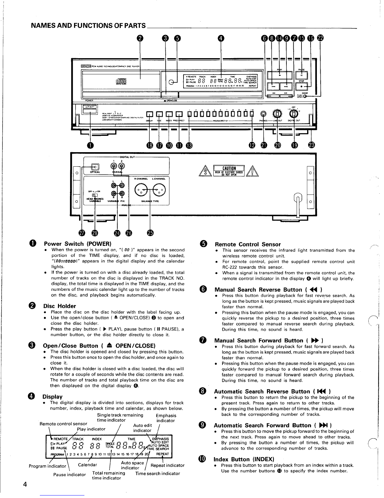
Play Button (
~
PLAY)
•Press
this
button
to
start
playback
of
adisc.
•When
this
button
is pressed, I• PLAYIis displayed, and
the
track
number
being
played
is
displayed
together
with
the
elapsed playback
time
of
the
track.
•Tracks are
shown
on
the
calendar display. Once atrack has been
played,
the
corresponding
track
number
goes
out
on
the
calendar display.
•
With
the
time
search
function,
playback can be started
from
specified
point
on
the
disc.
Gl
Pause Button (
II
PAUSE)
•Press
this
button
to
stop
playback
temporarily.
•
If
this
button
is pressed
during
playback, playback is stopped
temporarily,
the
I• PLAYI
indicator
goes
out
and
the
III PAUSE I
indicator
lights.
•Press
this
button
or
the
play
button
(
~
PLAY) again
to
continue
playback.
~
Stop Button ( • STOP)
•Press
this
button
to
stop
playback.
The
disc
will
stop
rotating,
and the
number
of
tracks and
total
playing
time
of
the
disc
are displayed in
the
TRACK NO. and
TIME displays, respectively.
•
In
case
programmed
playback is engaged
when
this
button
is
pressed,
the
number
of
tracks and total playing
time
of
the
program
are displayed.
4D
Time
Mode
Button (TIME)
•This
button
is used
to
select
the
desired indication in
the
TIME
display. The
indication
of
the
display
will
change each
time
the
button
is pressed.
Normally,
the
elapsed playback
time
of
the
current track is
displayed.
Pressing
the
button
once, tSINGLE Iis displayed and
the
remaining
time
of
the
current
track is displayed.
Pressing once
more,
ITOTAL tis displayed, and
total
playing
time
of
remaining
tracks is displayed. However,
when
program-
med
play
is in progress,
the
total
remaining
time
of
the
program
is displayed.
Press
the
button
once
again
to
return
to
the
normal
display
of
the
elapsed
playback
time
of
the
current
track.
fD
Display Button (DISPLAY)
•Press
this
button
to
change
the
brightness
of
the
display.
•Press once
to
make
the
display
2/3
as
bright
as
normal.
•Press once again
to
make
the
display
1/3
as
bright
as
normal.
•Press again
to
turn
the
entire
display
off
during
playback and all
but
the
track
number
off
in
any
other
mode.
G>
Digital
Output
Switch (DIGITAL OUTPUT)
•Use this
switch
to
turn
the
signals
from
the
digital
output
terminals
(DIGITAL OUTPUT) on and off.
•When
off,
no
digital
signals
are present on
the
output.
~
Volume Control (LINE OUT)
•Use
this
to
adjust
the
output
level
(volume)
of
the
headphones
or
the
line
output
(VARIABLE).
•The same operation is possible
using
the
included
remote
control
unit
(RC-222).
~
Headphones Jack (PHONES)
•For private listening, you can
connect
your
headphones
to
this
jack (PHONES). Do
not
raise
the
volume
level
too
much
when
listening
through
headphones.
(Headphones
are
sold
separ-
ately.)
~
Door Open Knob
•Press
to
open
the
door.
@)
Trap Door
•Opens
by
pressing
the
door
open knob.
To
close, press
the
right
side
of
the
door
gently.
~
Output
Terminal (FIX-VARIABLE)
•Connect these jacks
to
the
input
jacks on
your
amplifier.
(Refer
to
page 6
for
details on
the
connections.)
@)
Output
Terminals (BALANCED TYPE)
•These cannon
type
connectors
are balanced
outputs
with
an
output
impedance
of
6000.
Connect
them
to
the
balanced
input
terminals
on
the
amplifier.
•Cannon connector signal
layout
(Rear
output
terminals
..
,see Page
4-@))
WPin 1 -
common
~
6Pin 2 -
cold
3
oPin 3 -
hot
•Connector: Cannon
type
XLR-3-32
NOTE:
Do
not
short-circuit
the
hot
or
cold
pin
with
the
common
pin.
~
Digital Output Terminals (COAXIAL-1, COAXIAL-2)
•These
terminals
supply
digital
data.
•Use
the
included
RCA
pin cords
or
750
pin
cords
(available in
stores)
for
connecting.
oDigital Output Terminal (OPTICAL)
•This
terminal
outputs
digital
data
optically.
•Signals are
output
when
the
(DIGITAL OUT)
switch
is at
the
1,
2,
or
1
+2
positions.
@)
Headphone/Variable Output
On/Off
Switch
•Used
to
switch
the
signal
of
the
headphone
output
jack and
the
variable
output
jack
on
and off.
•In
the
off
position
the
signal is
not
output
to
the
headphone
output
jack
or
the
variable
output
jack.
Continuous Button Operation
If
the
automatic
search reverse
button
0,
the
automatic
search
forward
button
0,
or
the
+10
button
eEl
are held in,
the
function
of
that
button
will
be repeated.
5