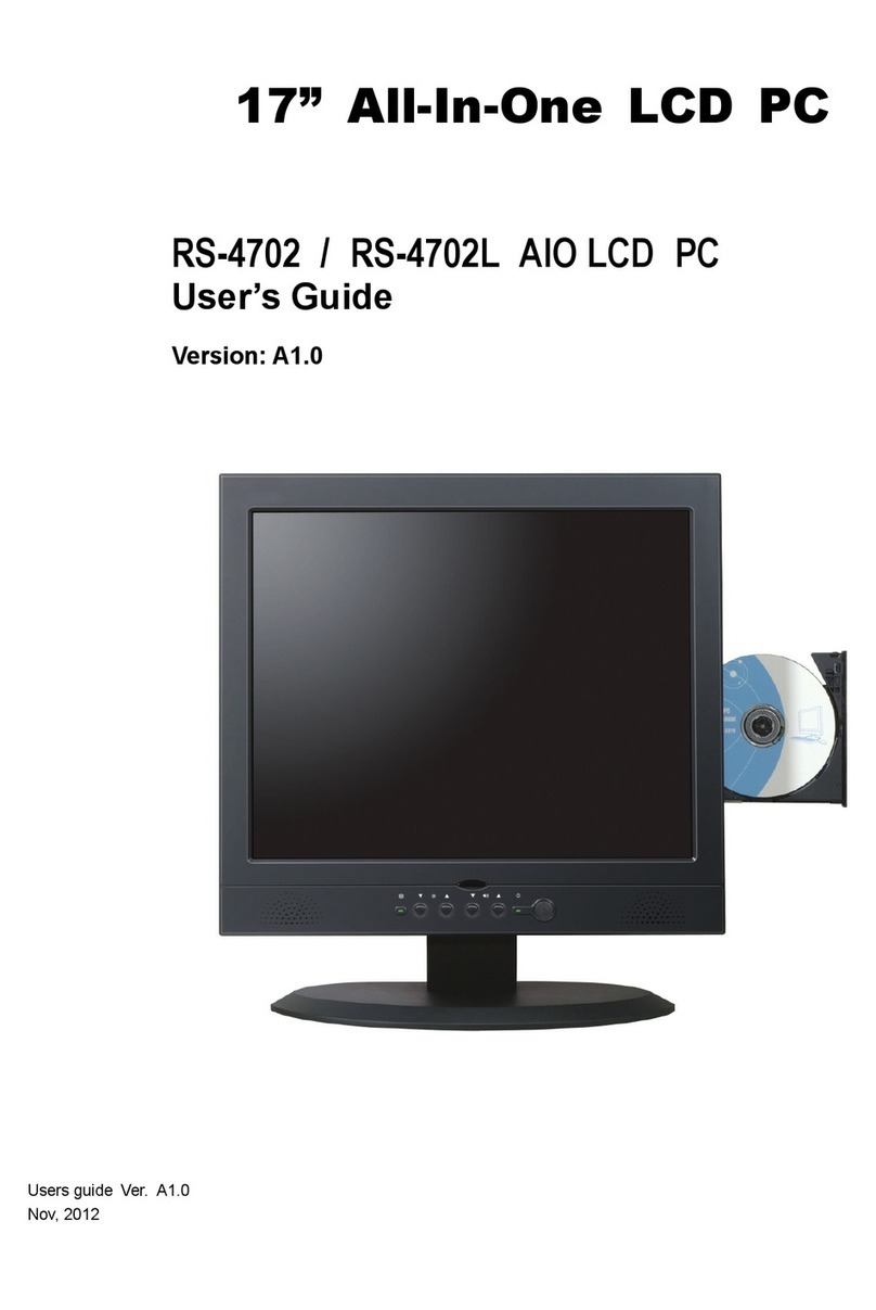
Densitron CASSIUS C3600 User manual

TCF/DCL/01/002 rev1 2/2/2001 PD
Appendix 4 Instruction Manual

G
ETTING
S
TARTED AND
R
EFERENCE
G
UIDE
C
ASSIUS
PC

ii Cassius PC Getting Started and Reference Guide
The contents of this manual and the associated software are the property of Densitron Corporation and are copyrighted.
Any reproduction in whole or in part is strictly prohibited.
Densitron Corporation have prepared this manual. It is furnished on the condition that the customer will use it solely for
the purpose of supporting the operation, service and maintenance of Cassius PC. The rights of the customer with respect
to this document will be governed by mutually acceptable provisions of the contract with Densitron Corporation or its
authorised distributor. This document shall not be duplicated by the customer, released, disclosed or used in whole or
part, for any purpose other than that stated herein, without the express written permission of Densitron Corporation.
Although every effort has been made to ensure that the contents of the document are accurate, Densitron Corporation and
its authorised distributor assume no responsibility for any errors contained herein.
Intel, Pentium and Celeron are registered trademarks of Intel Corporation. Microsoft and Windows are registered
trademarks of the Microsoft Corporation in the United State and/or other countries. PS/2 is a registered trademark of the
IBM Corporation. Cassius PC is a registered trademark of Densitron Corporation. Other company, product, or service
names may be the trademarks or service marks of others.
All other trademarks, trade names, and product names are trademarks or registered trademarks of their respective holders.
Information in this document is subject to change without notice.
Copyright© 2000 Densitron Computers Ltd.
Published November 2000.
Document number (DEN-CAS-1.00-GR-1.00A-UK)
Version 1.0 C3600 Cassius
Document Revision History
Revision Date Comments
1.0 7/12/2000 First release

Contents
About This Guide..................................................................................................................................v
Documentation Available vi
Typographical Conventions vi
C H A P T E R 1 1–1
Getting Started..................................................................................................................................1–1
What’s in the Box? 1–2
Getting to Know your Cassius PC 1–3
Cordless Keyboard and Mouse 1–11
Safety Precautions 1–15
Switching On 1–18
Windows 2000 Emergency Repair Diskette (where applicable) 1–20
C H A P T E R 2 2–1
Using your Cassius PC......................................................................................................................2–1
Introduction 2–2
Remote Control 2–2
TV Tuner 2–4
FM Radio Tuner 2–6
DVD Player 2–7
C H A P T E R 3 3–1
Maintaining your Cassius PC ..........................................................................................................3–1
Introduction 3–2
Cleaning your Cassius PC 3–2
Memory Expansion 3–2
System Battery Replacement 3–4
PC Card Slot 3–6
Other Queries 3–7
C H A P T E R 4 4–1
Reinstalling Software........................................................................................................................4–1
Reinstalling Drivers 4–2

iv Cassius PC Getting Started and Reference Guide
Obtaining New Drivers 4–2
Reinstalling Programs 4–2
C H A P T E R 5 5–1
Bios Setup ..........................................................................................................................................5–1
The BIOS Setup 5–2
Using the Bios Setup 5–2
Changing your Bios Settings 5–3
C H A P T E R 6 6–1
Troubleshooting................................................................................................................................6–1
Problems Switching On 6–2
Problems with your Keyboard and Mouse 6–4
A P P E N D I X A A–I
Regulatory Statements and Battery Disposal.................................................................................A–I
CE Symbol A–II
FCC Part 68 A–II
FCC Part 15 A–III
Laser Compliance Statement A–IV
Disposing of the System Battery A–V
Liquid Crystal Display Warning A–V
Macrovision Copy Protection A–VI
Japanese Telecommunication Business Law A–VI
A P P E N D I X B B–1
Overview........................................................................................................................................... B–1
Computers Explained B–2
Your Cassius PC B–5
Index.........................................................................................................................................................

About This Guide
This section describes the contents and conventions of this guide and provides
a list of available Cassius PC documentation.
The Cassius PC Getting Started and Reference Guide contains the chapters
and appendix shown below.
Chapter 1: Getting Started — Describes how to start using your Cassius PC.
Chapter 2: Using Your Cassius PC — Describes ways you can use your
Cassius PC.
Chapter 3: Maintaining Your Cassius PC — Describes how to maintain and
upgrade your Cassius PC.
Chapter 4: Reinstalling Software — Describes how to reinstall software on
your Cassius PC.
Chapter 5: Bios Setup — Describes the bios setup facility.
Chapter 6: Troubleshooting – Describes how to resolve problems with your
Cassius PC.
Appendix A: Regulatory Statements and Battery Disposal — Describes the
CE symbol, the FCC statements to which your Cassius PC conforms and how
to dispose of your system battery.
Appendix B: Overview – Provides a specification of your Cassius PC and a
brief explanation of some computer terminology.

vi Cassius PC Getting Started and Reference Guide
Documentation Available
The Cassius PC documentation set consists of:
Cassius PC Getting Started and Reference Guide — Describes how to set up
and use your Cassius PC.
www.cassiuspc.com and www.cassiuspc.co.uk — Provides online information
about your Cassius PC.
Typographical Conventions
This guide uses the typographical conventions shown below.
Convention Used
Italic For cross-references.
Bold For features, buttons, menu
options and field names.
> To indicate a menu option.
For example, Select
File > Exit.
! Bullets For lists and instructions.

C H A P T E R 1
Getting Started
This chapter describes how to start using your Cassius PC.
In This Chapter
! What’s in the Box
! Getting to Know your Cassius PC
! The Cordless Keyboard and Mouse
! Safety Precautions
! Switching On
! Windows 2000 Emergency Repair Diskette

1–2 Cassius PC Getting Started and Reference Guide
What’s in the Box?
Your Cassius PC comes with the equipment listed below.
! Main unit, including a stand.
! Cordless keyboard and wrist rest.
! Cordless mouse.
! Batteries for the keyboard and mouse.
! Hardware drivers on the Cassius PC Software CD.
! Software disks and licence documentation for the operating system.
! AC power cord.
! Cassius PC Getting Started and Reference Guide.
! FM antenna (Cassius Intertainment Only).
! Remote control handset (Cassius Intertainment Only).

Chapter 1 Getting Started 1–3
Getting to Know your Cassius PC
Front View of your Cassius PC
The front view of your Cassius PC is shown below.
Each feature is described below.
Item Description Function
A Stand Supports your Cassius PC.
B 15” Flat Screen Provides a sharp, flicker free display.
C Button Panel Refer to Button Panel, page 1–7.
D Integral Speakers Outputs stereo audio.

1–4 Cassius PC Getting Started and Reference Guide
Rear View of your Cassius PC
The rear view of your Cassius PC is shown below.
Each feature is described below.
Item Description Function
A Power Socket Connect your AC power cord to this port.
B Connection Block 1
(Intertaiment Only) Refer to Connection Block .
C Connection Block 2 Refer to Connection Block 2.
D Heat Vents Used to help keep the system cool. DO NOT
BLOCK.
E Memory Door Used to access the memory bay for upgrading
memory and replacing the CMOS Battery.

Chapter 1 Getting Started 1–5
Item Description Function
F VESA Mounting
Plate Attaches your Cassius PC to any VESA
Standard mounting arms or stands.
Side View of your Cassius PC
The side view of your Cassius PC is shown below.
Each feature is described below.
Item Description Function
A Floppy Disk Drive
(3½ inch). The eject button
is at the top of the drive.
For use with 3.5” floppy disks. Insert
floppy discs with the label towards
the front of your Cassius PC.

1–6 Cassius PC Getting Started and Reference Guide
Item Description Function
B DVD Drive (Intertainment)
or CD ROM Drive (Pro) The DVD drive accepts all CDs and
DVDs. The CD drive will accept
CDs only. The eject button only
operates with power. After ejecting
the tray, draw it out fully. Insert disc
firmly, pushing at centre until it
clicks in place over the spindle with
the label visible. If the unit is
switched off, you can eject the
CD/DVD tray by inserting a
straightened paper clip into the hole
beside the eject button.
Bottom View of your Cassius PC
The bottom view of your Cassius PC is shown below.
The table below describes each feature.
Item Description Function
A USB Socket Allows you to connect external USB
devices.
B Rotary Volume Control Sets volume level for the built-in
speakers.

Chapter 1 Getting Started 1–7
Item Description Function
C Headphone Socket Allows you to connect headphones.
Speakers become mute when you
connect headphones.
D PCMCIA Socket Allows you to connect Type I and
Type II PC Cards. Either the blank
card supplied or your PCMCIA card
should be in this socket. The socket
should not be left empty.
Button Panel
The button panel of your Cassius PC is shown below.
The table below describes each feature.
Item Description Function
A Internal
Microphone Allows you to provide audio input.
B LCD Brightness
Control Buttons Brightness setting remains the same when the
system is switched off.
C USB Socket Allows you to connect external USB devices.
D Rotary Volume
Control Sets volume level for the built-in speakers.
E Headphone Socket
Allows you to connect headphones. Speakers
become mute when you connect headphones.
F Infrared Window
For use with the remote control and IrDA
function. Keep this window clean.

1–8 Cassius PC Getting Started and Reference Guide
G Three LEDs and a
button for the
internal wireless
keyboard.
The left LED indicates Caps Lock; the centre
LED indicates Num Lock; the right LED and
the button are for connection, refer to the
manual for the keyboard. These LEDs only
show the status of the wireless keyboard. If an
external keyboard is plugged into the purple
external keyboard socket on the rear of your
Cassius PC the status of Num Lock and Caps
Lock will be indicated by LEDs on the
external keyboard.
H Disc Drive Activity
LED Flickers when data is transferring between
drives.
I Standby Button
Allows you to put your Cassius PC into
standby mode.
J Power Switch Allows you to switch on or off your Cassius
PC.
K Power LED LED Status Meaning
Off No power
Orange Closed down
Flashing Orange Standby mode
Flashing green Sleep mode
Green Operational.
L Hardware Reset
Button Use a straightened paper clip to press this
button if the Cassius PC stops responding.
Rear Connection Blocks
The two connection blocks at the rear of your Cassius PC are shown below.
Connectors that are only present on the Cassius Intertainment are indicated in
the text below.

Chapter 1 Getting Started 1–9
Connection Block 1
Connection block 1 at the rear of your Cassius PC is shown below.
The table below describes each feature.
! Ext. KBD/MS (RF DIS.) — RF device switch. Allows you to enable or
disable the wireless keyboard and mouse. Your Cassius PC is supplied
enabled (switch down). If you want to use a conventional PS/2 keyboard
and mouse, move this switch up to disable RF keyboard and mouse.
! Mouse (green) — External PS/2 mouse port. To enable this port, move
the RF DIS switch up.
! Keyboard (purple) — External PS/2 keyboard port. To enable this port,
move the RF DIS switch up.
! Printer (red) — Parallel printer port.
! COM1 (dark green) — Serial (RS-232) port.
! VGA (blue) — External VGA video port to connect an external analogue
monitor. This allows the system to drive two displays simultaneously.
! LAN (top) — Connector for a 10/100Base-T Ethernet LAN connection.
Use a category five LAN cable for this port. Two LEDs above the port
indicate successful connection (yellow) and data flow (green).
! USB (bottom) — Two USB ports for connecting external USB devices.
! GAME (yellow) — Game port for connecting a joystick or MIDI device.
(Intertainment)
! LINE OUT (green) — Line out audio jack connector. Colour coded in
accordance with the Intel Microsoft PC 1999 specifications.

1–10 Cassius PC Getting Started and Reference Guide
! LINE IN (blue) — Line in audio jack connector. Colour coded in
accordance with the Intel Microsoft PC 1999 specifications.
! MIC (red) — Microphone jack connector. Colour coded in accordance
with the Intel Microsoft PC 1999 specifications.
Connection Block 2
Connection block 2 at the rear of your Cassius PC is shown below.
Each feature is described below.
! MODEM — Modem socket.
! FM AERIAL — FM radio antenna connection. (Intertainment)
! VHF RF AERIAL — TV antenna connection or satellite/cable
connection. (Intertainment)
! SVIDEO OUT — S-video output for connection to external television and
video devices. (Intertainment)
! COMP OUT — Composite video output socket for connection to external
television and video devices. (Intertainment)
! SVIDEO IN — S-video input to display video from an external source.
(Intertainment)
! COMP IN — Composite video input to display video from an external
source. (Intertainment)
! S/PDIF OUT — S/PDIF output socket to stream digital audio from DVD
discs. You can use this to connect to an external digital decoder.
(Intertainment)

Chapter 1 Getting Started 1–11
! POWER IN — IEC three-pin power input connector.
Cordless Keyboard and Mouse
This section explains how to:
! Install batteries in the keyboard and mouse.
! Switch your Cassius PC to using a normal keyboard and mouse using the
Ext. KBD/MS switch on the back of your Cassius PC.
Keyboard
The side view of your keyboard is shown below.

1–12 Cassius PC Getting Started and Reference Guide
Mouse
The top view of your mouse is shown below.
The table below describes each feature.
Item Description Function
A Left Mouse Button Allows you to select buttons, menus and other
software features.
B Mouse Wheel Allows you to scroll through some
applications.
C Right Mouse
Button Allows you to use context sensitive menus and
other software features.

Chapter 1 Getting Started 1–13
The bottom view of your mouse is shown below.
The table below describes each feature.
Item Description Function
D Connect Button
Used for manually connecting RF mouse to
your Cassius PC. Refer to Manually
Connecting the Cordless Keyboard and Mouse
below.
E Mouse Ball If mouse operation is unreliable, this may need
cleaning.
The cordless keyboard and cordless wheel mouse require batteries. A set of
batteries is supplied.
The keyboard requires two AA alkaline batteries and the mouse requires two
AAA alkaline batteries.
You should replace the batteries when prompted by the computer. Use alkaline
batteries for best performance; other battery types are acceptable, but do not
mix types.
Table of contents
