DENT-X ROTOGRAPH PLUS User manual
Release 4 December 2006 (Rev. 0)
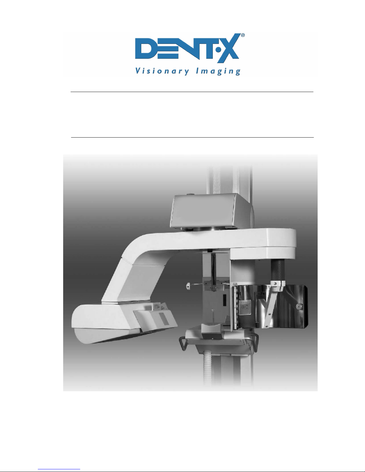
ROTOGRAPH PLUS
ROTOGRAPH PLUSROTOGRAPH PLUS
ROTOGRAPH PLUS
(120V version)
(120V version)(120V version)
(120V version)
Service manual
Service manualService manual
Service manual

SERVICE MANUAL
Contents
(Rev. 0) RTG PLUS (120V)
i
Contents
1. INTRODUCTION 1-1
1.1 Icons appearing in the manual ............................................................ 1-1
2. SAFETY INFORMATION 2-1
2.1 Warnings ............................................................................................. 2-2
2.2 Environmental risk and disposal ......................................................... 2-3
2.3 Symbols used ...................................................................................... 2-4
3. DESCRIPTION 3-1
3.1 Identification labels ............................................................................. 3-1
3.2 Description .......................................................................................... 3-3
4. TECHNICAL FEATURES 4-1
4.1 Standards and regulation .................................................................... 4-4
4.2 X-ray tubehead curves ........................................................................ 4-5
4.2.1 Tube "CEI - OPX/105" (0.5x0.5)........................................................4-5
4.3 Technical factors measuring method ................................................... 4-7
4.4 Overall dimension................................................................................ 4-8
5. PRE-INSTALLATION 5-1
5.1 Electrical requirements ....................................................................... 5-2
5.2 Environmental condition ..................................................................... 5-3
5.3 Unpacking ........................................................................................... 5-3
5.4 Space requirements............................................................................. 5-4
5.4.1 PAN versions....................................................................................5-4
5.4.2 CEPH version ...................................................................................5-5
6. INSTALLATION 6-1
6.1 Panoramic version with legs ................................................................ 6-2
6.2 Panoramic version - wall mounted (no legs)......................................... 6-7
6.3 Panoramic version with CEPH ........................................................... 6-11
6.4 Converting from “CEPH” configuration to “Prepared for CEPH”.......... 6-12
7. CHECKOUT AND ADJUSTMENTS 7-1
7.1 Power up ............................................................................................. 7-1
7.2 Set-up ................................................................................................. 7-2
7.2.1 Activation of the set-up programs .....................................................7-2
7.2.2 Modification of the values of the "Software DIP-Switches" ..................7-3
7.2.3 Non-volatile memory reset ................................................................7-7
7.2.4 Potentiometer replacement/calibration .............................................7-8

SERVICE MANUAL
Contents
RTG PLUS (120V) (Rev. 0)
ii
7.3 Checking and adjusting the AC voltage ............................................. 7-11
7.3.1 Check of line voltage regulation ...................................................... 7-12
7.4 Checking the output current (mA) ..................................................... 7-13
7.4.1 First solution (rotating arm in movement) ....................................... 7-13
7.4.2 Second solution (rotating arm blocked) ........................................... 7-13
7.5 Checking and centering adjustment of the X-ray beam ..................... 7-15
7.5.1 Alignment of the X-ray beam for the PANORAMIC mode .................. 7-16
7.5.2 Centering of the X-ray beam for the CEPH mode ............................. 7-19
7.5.3 Adjustment of the soft tissue filter for CEPHALOMETRIC
teleradiography .............................................................................. 7-21
7.5.4 Adjustment of patient's auricular aperture centering rings in
latero-lateral cephalometric teleradiography.................................... 7-22
7.5.4.1 Projection of Horizontal Non-Concentric
Ear Centering Circles........................................................ 7-23
7.5.4.2 Projection of Vertically Non-Concentric
Ear Centering Circles........................................................ 7-24
7.6 Angle (A…) and Time (T…) control...................................................... 7-25
7.7 Changing angles and times................................................................ 7-27
7.7.1 PAN-ADULT ................................................................................... 7-28
7.7.2 PAN-CHILD.................................................................................... 7-30
7.7.3 TMJ1 and TMJ2 - ADULT and CHILD ............................................. 7-32
7.7.4 Verification of Panoramic centering and symmetry .......................... 7-36
7.8 Message on the display of remote control .......................................... 7-38
7.8.1 Line voltage too high / too low........................................................ 7-40
7.8.2 Impossible to regulate the line voltage ............................................ 7-41
7.8.3 Memory data corrupted. Call Technical Assistance.......................... 7-42
7.8.4 "NO ANSWR".................................................................................. 7-42
7.8.5 Out of Order N°1! Call Technical Assistance.................................... 7-43
7.9 Checking (safety) hardware timers..................................................... 7-44
7.10 System reconfiguration after testings ................................................ 7-45
8. MAINTENANCE 8-1
9. SCHEMATICS AND DRAWINGS 9-1
9.1 Key to general diagram of the Rotograph Plus...................................... 9-2
10. SPARE PARTS 10-1
This publication can only be reproduced, transmitted, transcribed, or translated
into any human or computer language with the written consent of DENT-X.
This manual in English is the original version.
SERVICE MANUAL
Introduction
(Rev. 0) RTG PLUS (120V)
1-1
1.
1.1.
1.
INTRODUCTION
INTRODUCTIONINTRODUCTION
INTRODUCTION
NOTE:
The present manual is updated for the product it is sold with in order to
grant an adequate reference in performing diagnostics and repair
operations normally carried out by the service engineer.
The manual may not reflect changes to the product not impacting service
operations.
ROTOGRAPH PLUS, by DENT-X, is a radiological device which allows to
carry out radiological examinations of the dento maxillo facial complex.
ROTOGRAPH PLUS is available in the following version:
• For PANORAMIC examination only (ST version)
• For PANORAMIC examination and examination of the Temporo-
Mandibular Joint (TMJ)
• The latter is also available with the CEPHALOMETRIC device in order
to carry out CEPHALOMETRIC (CEPH) examination.
This manual provides to the operator the instructions for proper and safe
use of the appliance.
The appliance must be used strictly following the procedures described
in this manual and never for activities other than those for which it was
designed.
Before using the appliance, we recommend to read carefully this manual.
Keep it in a safe place near the unit for future reference.
ROTOGRAPH PLUS is an electromedical appliance and may be used only
under medical supervision, i.e. with the supervision of highly qualified
persons with the necessary know-how regarding X-ray protection.
The user is responsible for complying with the legal requirements
regarding the installation and operation of the equipment.
1.1
1.11.1
1.1
Icons appearing in the manual
Icons appearing in the manualIcons appearing in the manual
Icons appearing in the manual
Indicates a “NOTE”; the utmost attention shall be devoted to the
reading of paragraphs marked by this icon.
Indicates a “WARNING”; paragraphs marked with this icon cover
patient and/or operator safety aspects.
*
*

SERVICE MANUAL
Introduction
RTG PLUS (120V) (Rev. 0)
1-2
THIS PAGE IS INTENTIONALLY LEFT BLANK

SERVICE MANUAL
Safety information
(Rev. 0) RTG PLUS (120V)
2-1
2.
2.2.
2.
SAFETY INFORMATION
SAFETY INFORMATIONSAFETY INFORMATION
SAFETY INFORMATION
WARNING:
Read this chapter very carefully.
VILLA SISTEMI MEDICALI and DENT-X designs and manufactures
equipment in compliance with safety requirements; moreover, it provides
all the necessary information for correct utilization as well as warnings
related to risks associated to X-ray generators.
Villa Sistemi Medicali or DENT-X shall not be responsible for:
• any use of the ROTOGRAPH PLUS different from that for which it
has been designed,
• any damage to the equipment, the operator or the patient caused
either by incorrect installation and maintenance not compliant with
the procedures contained in the relevant user’s and installation
manuals provided with the equipment, or by incorrect operation
techniques,
• any mechanical and/or electrical changes effected during or after
installation, different from those reported in the service manual.
Only qualified service personnel, authorized by DENT-X is allowed to
perform technical interventions on the equipment.
Only authorized personnel is allowed to remove the tubehead from
its support and access the internal components.

SERVICE MANUAL
Safety information
RTG PLUS (120V) (Rev. 0)
2-2
2.1
2.12.1
2.1
Warnings
WarningsWarnings
Warnings
The system has not been designed to be used in presence of vapours,
anaesthetic mixtures that are flammable with air, or oxigen or nitrous
oxide.
Ensure that water or other liquids do not get into the machine so as to
prevent short-circuits and corrosion.
Always disconnect from mains before cleaning the machine.
Where necessary, accessories such as lead-sealed aprons must be used
to protect the patient from radiations.
Only the patient and the operator may remain in the room during the
execution of the radiography examination.
ROTOGRAPH PLUS has been developed for continuous use with
intermittent load. The prescribed operating cycles to allow the heat
accumulated by the radiogenic source to be discharged must be
observed.
Although the appliance has been designed to have a reasonable degree of
protection from electromagnetic interference, it must be installed at a
certain distance from electricity transformer rooms, static continuity
unit, portable two-way hand radios and cellular phones. The latter may
only be used at a distance of over 1.5 meters from all elements of the
machine.
All instruments or equipment for professional use and used near the
machine must be in conformance to the electromagnetic compatibility
standards.
Nonconforming instruments whose low immunity to electromagnetic
fields is known must be installed at least 3 meters away from the
ROTOGRAPH PLUS and be powered via an independent electric line.
ROTOGRAPH PLUS must be switched off during the entire period of use
of ESU (Electro Surgery Units) units or similar equipment.
Clean or eventually disinfect the chin support, positioning handles,
temples clamp support, nose rest and any other part that may come in
touch with the patient.
At the end of the examination, replace the bite and the ear rods.
SERVICE MANUAL
Safety information
(Rev. 0) RTG PLUS (120V)
2-3
Although the X-ray dosage supplied by dental radiology appliances is on
average low and distributed over a relatively small surface, the operator
must take the necessary precautions and/or follow the safety procedures
for both himself and the patient during an exposure. We recommend
that the X-ray activation always be commanded from an X-ray protected
area via remote control. If it is necessary to operate the exposure near
the patient, remain at the maximum distance allowed by the remote
control cable in the direction opposite to the emission of the rays, at a
distance of at least 78 ¾ inches (2 meters) from both the radiation
source and patient.
2.2
2.22.2
2.2
Environmental risk and disposal
Environmental risk and disposalEnvironmental risk and disposal
Environmental risk and disposal
A number of machine parts contain materials and liquids that upon
completion of the machine’s life cycle must be disposed of at recovery
centers established by the local health units.
The machine contains the following materials and/or components:
• Tubehead: dielectric oil, lead, copper, iron, aluminum, glass,
tungsten, beryllium
• Control box and remote control: iron, copper, glass resin, non-
biodegradable plastic casings
• Column, rotating arm, extensions: iron, lead, aluminum, copper,
non-biodegradable plastic materials, glass resin.
WARNING:
Before disassembling the parts, lock the counterweight of the slider
inserted in the column. This is possible only after having slid the slider
all the way down and inserted a pin approximately 25cm in length and
8mm in diameter. Once the pin has been inserted, move the slider
towards the top until the counterweight rests on the pin. Remove the
tubehead and some of the parts of the rotating arm. Holding the slider
firmly, remove the pin and move the slider towards the top to the
metallic stop of the column. At this point, remove all the remaining
parts.
SERVICE MANUAL
Safety information
RTG PLUS (120V) (Rev. 0)
2-4
2.3
2.32.3
2.3
Symbols used
Symbols usedSymbols used
Symbols used
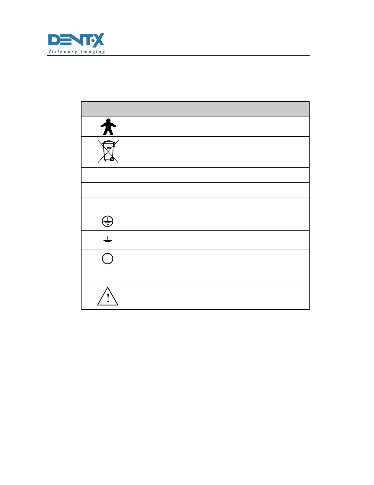
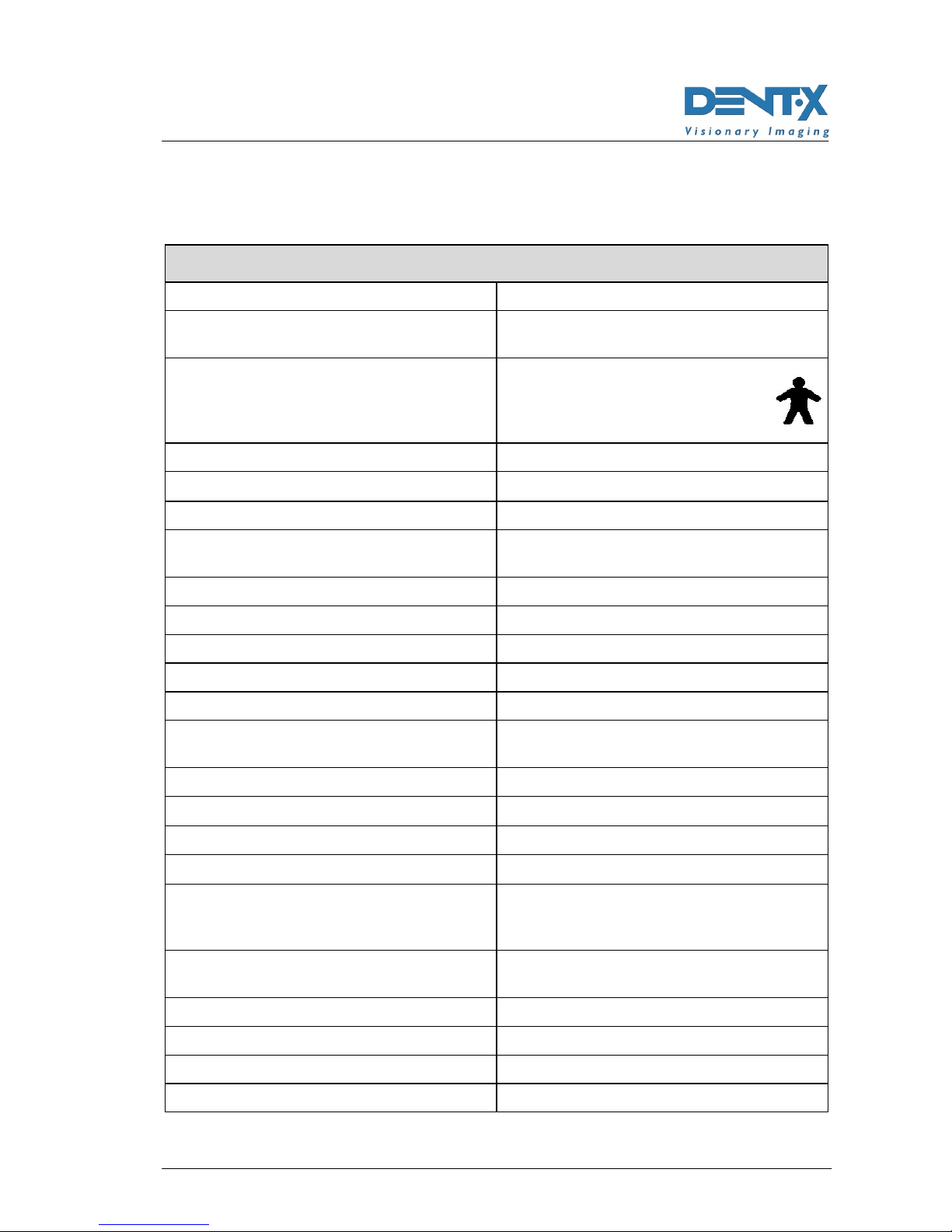
Symbol Description
Equipment with Type B applied parts (according to
IEC 601-1)
A number of machine parts contain materials and
liquids that upon completion of the machine’s life
cycle must be disposed of at recovery centers
established by the local health units
∼
∼∼
∼Alternating Current
N Connection to neutral conductor
L Connection to line conductor
Protection ground
Functional ground
OFF ; equipment not connected to power line
ON ; equipment connected to power line
Warning: read the documentation provided with the
unit
SERVICE MANUAL
Description
(Rev. 0) RTG PLUS (120V)
3-1
3.
3.3.
3.
DESCRIPTION
DESCRIPTIONDESCRIPTION
DESCRIPTION
3.1
3.13.1
3.1
Identification labels
Identification labelsIdentification labels
Identification labels
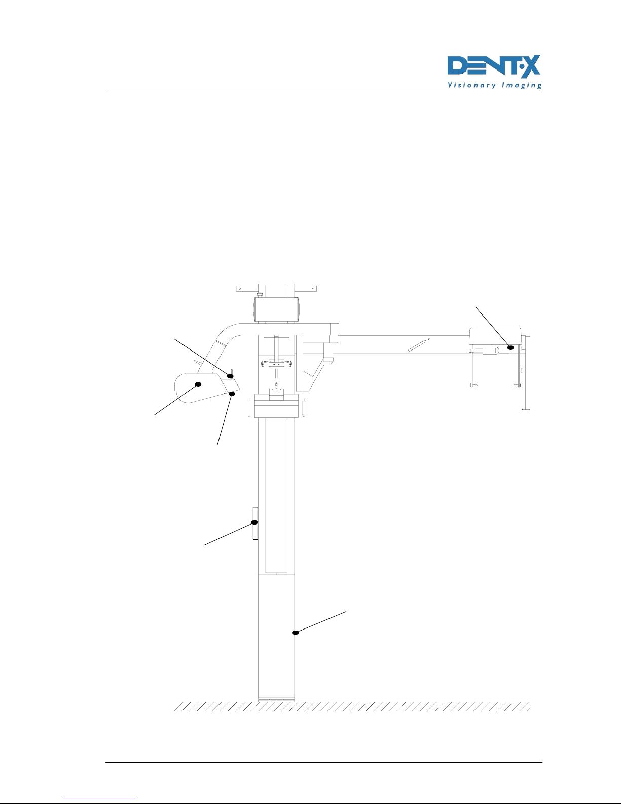
ROTOGRAPH PLUS is labeled with a set of labels identifying different
components according to the requirements of the international
standards.
The following picture shows the position of the different labels:
1
2
3
4
6
5

SERVICE MANUAL
Description
RTG PLUS (120V) (Rev. 0)
3-2
1a
ROTOGRAPH PLUS
label
1b
WARNING label
1c
ETL certification
label
2
Tubehead label
3
Collimator label
4a
Diaphgram label
(not present on “ST” version)
4b
Diaphgram label
(not present on “ST” version)
5
Remote control label
6
CEPH device label

SERVICE MANUAL
Description
(Rev. 0) RTG PLUS (120V)
3-3
3.2
3.23.2
3.2
Description
DescriptionDescription
Description
ROTOGRAPH PLUS has been designed to perform the following
examinations:
• Panoramic examination (all versions)
• "SINUS" examination of the paranasal sinus (all versions)
• Examination of the Temporo-Mandibular Joints (TMJ) with open or
closed mouth on a single film (not available on "ST" version)
• Cephalometric examinations (CEPH) of the skull (if equipped with
the cephalometric optional device; not available on "ST" version) with
65 inches (1.65 mt.) focus-film distance and 59 inches (1.5 mt.)
focus-patient distance.
All the allowed examination may be made with different parameters
according to the setting of the remote-control (please refer to the specific
chapter of this manual).
ROTOGRAPH PLUS is controlled by a soft touch console and equipped
with an alphanumeric digital display for a clear indication of the working
parameters and operative messages. The operative cycle is entirely run
by a microprocessor, controlling its different modes : from programming
of the emission parameters according to the chosen examination and
the patient's size, to the voltage fluctuation and to the notification of
possible anomalies, failures or errors.
The excellent quality radiographs thus obtained is the result of a clever
design based upon the pseudo-elliptic rotation system, the original light
beam-luminous cross pattern centering system, the use of green emiting
Rare Earth Intensifying screens and most of all the small dimension of
the focal spot.
This particular rotation system allows an orthogonal imaging of all teeth
and wide image layer with an optimum focused zone of 10 mm for the
incisors and 20 mm for the molars.
ROTOGRAPH PLUS, besides operating in the programmed mode, can
also operate in the manual personalized mode by modification of the
parameters, as described in chapter 5.
In the Panoramic and TMJ modes, with all interlock enabled, it is
possible to activate the TEST push button (31) (see Figure 7-13 at the
end of the manual).
The TEST functioning mode allows the operator to check the
functionality of the selected examination cycle or to show to the patient
the examination he will undergo (including all movements of the
machine) without emitting X-rays.

SERVICE MANUAL
Description
RTG PLUS (120V) (Rev. 0)
3-4
The TEST push button as X-RAY button is a “dead man” button, which
means thus if it is released during the examination cycle, the latter is
interrupted stopping the movements in progress. To re-start the cycle
first reset the unit by means of the key 32 (Figure 7-13), than start again
the function which was interrupted.
The following intensifying screen - film combinations are recommended
in order to obtain good quality images:
Intensifying screens Films
Type Supplier Type Supplier
KR II KONIKA MG KONIKA
KR II KONIKA MGH KONIKA
Lanex
Regular KODAK T-MAT G/RA KODAK
Curix Ortho
Regular AGFA T-MAT G/RA KODAK
T 16 3M / IMATION XDA 3M / IMATION
Medium AGFA HTA AGFA
G8 FUJI HR-G FUJI
The above listed intensifying screens are all of the Green Rare Earth
emitting type.
Use of screens and films different from those stated on the table above
requires system recalibration by an Authorized Technician.
The calibration of the above mentioned combination has only an
indicative value. The effective adjustment depends on different factors,
such as the real dose emitted by the unit, the film development system
and the user predilection for more or less devise images.
The good quality of the image does not exclusively depend on
ROTOGRAPH PLUS but a great importance is to be given to the film
developer; and dark room techniques.
Therefore, it is necessary:
• to perform developer maintenance as indicated by the manufacturer
instructions;
• to check regularly the level of the used chemical substances,
substituting them at time intervals as indicated by the manufacturer
instructions, usually a direct function of the number of radiographs
developed and chemicals concentration.
SERVICE MANUAL
Technical features
(Rev. 0) RTG PLUS (120V)
4-1
4.
4.4.
4.
TECHNICAL FEATURES
TECHNICAL FEATURESTECHNICAL FEATURES
TECHNICAL FEATURES
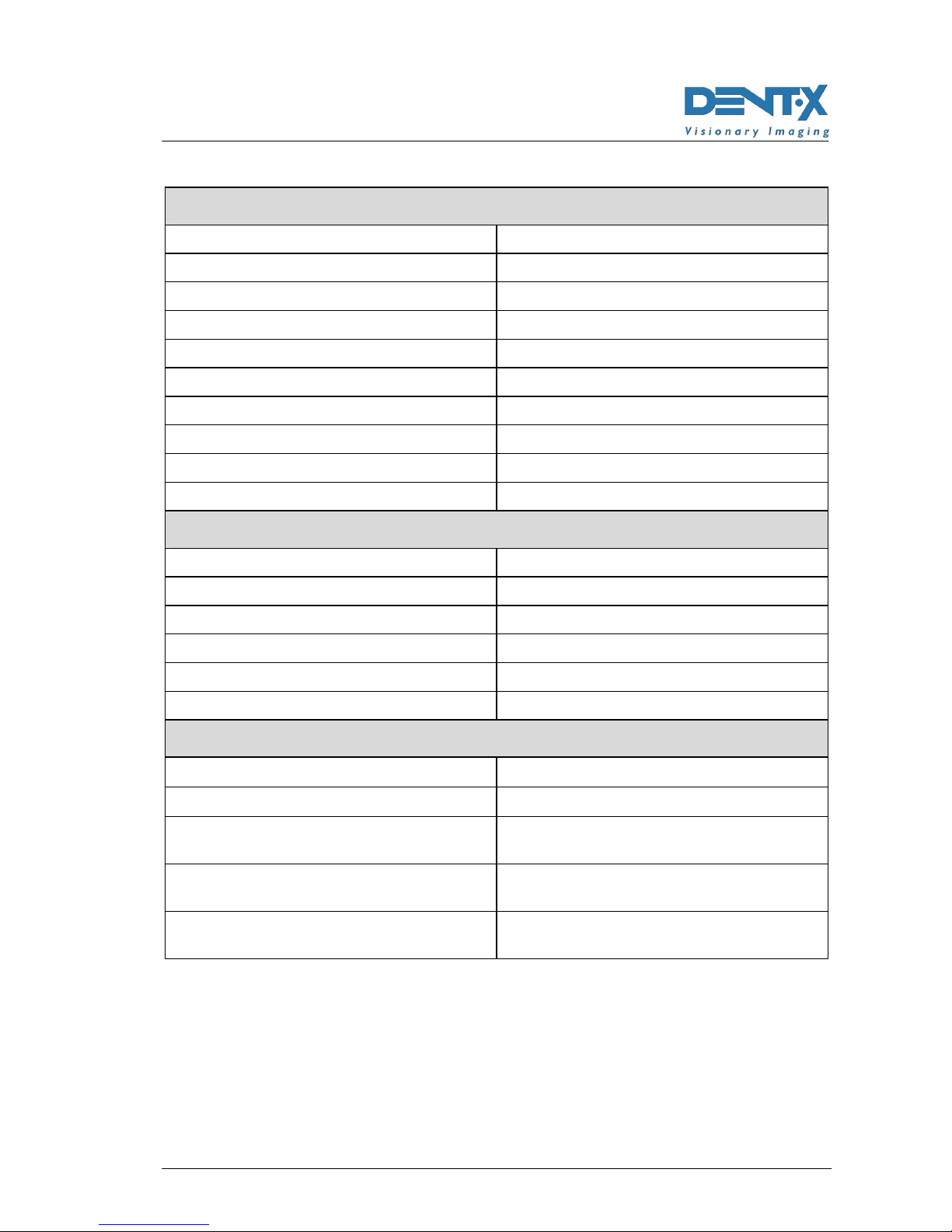
General characteristics
Equipment ROTOGRAPH PLUS
Manufacturer VILLA SISTEMI MEDICALI
Buccinasco (MI) Italy
Class Class II according to 21 CFR
sub-chapter J.
Class I with type B applied parts
according to IEC.
Degree of protection IP20
Rated line voltage 120V ±10%
Line frequency 60Hz
Max line current at 108V, 85kV, 10mA
(see Note 2)
10A rms momentary; 0.5A stand-by
Maximum power 1.15 kVA at 108V
Power fuse 10A T
Command fuse 0.5A T
Filament fuse 0.315A F
Line voltage regulation ≤3% at 108V
Compensation of the mains voltage
fluctuation
automatic
High voltage 60-85 kV (5 kV steps)
KV accuracy ±10% @ 120V ±10%
Anodic current 10 mA
Anodic current accuracy ±1.5 mA @ 120V ±10%
Exposure time (Panoramic)
(with deceleration ramp)
17s adult
14s child
15s child
Exposure time (TMJ1 + TMJ2)
(see note 1)
10.4s adult
9.4s child
Exposure interval (PAN & TMJ) 240s (1:16 duty cycle)
Film size (PAN & TMJ) 6"x12"
Image mean enlargement (PAN & TMJ) 1.2 : 1
Inherent filtration of the PAN cassette 1mm Al eq @ 70 kV

SERVICE MANUAL
Technical features
RTG PLUS (120V) (Rev. 0)
4-2
General characteristics
Exposure time (Cephalometric)
(see note 1)
0.2 ÷3s in 19 position
Exposure time accuracy (CEPH) ±10ms for times ≤0.33s0
±3 % for times ≥0.33s
Reference current time product (CEPH) 3 mAs @ 70% of the max power
Exposure interval (CEPH) 60s
Film size (CEPH) 8"x10" std.
12"x10" optional
24x30 cm optional
Focus-Patient distance (CEPH) 59" (150cm)
Focus-Film distance (CEPH) 65" (165cm)
Image mean enlargement (CEPH) 1.1 : 1
Cassette front panel filtration <1mm Al.
NOTE 1:
These examination are not available on the "ST" version; this feature
cannot be field upgraded.
NOTE 2:
Due to technology used to compensate the line voltage fluctuations, the
maximum of line current absorbed from the line is at the lowest voltage
(108V).
Tubehead features
Type MR05
Manufacturer VILLA SISTEMI MEDICALI
Buccinasco (MI) Italy
Max peak tube potential 85 kV
Nominal power 0.630 kW (85kVp, 10mA)
Total filtration 2.5mm Al eq. at 85 kV
Insulation Oil bath
Cooling Ambient
Leakage radiation at 1 m < 0.25 mGy/h
(85 kV, 10mA, 1:16 duty cycle)
Maximum power 85 kVp, 10mA
Type of circuit Single-phase, self-rectifying
*
*
SERVICE MANUAL
Technical features
(Rev. 0) RTG PLUS (120V)
4-3
X-ray tube features
Manufacturer CEI – Bologna Italy
Type CEI OPX/105
Focus 0.5 IEC 336
Inherent filtration 0.5 mm Al eq.
Anode tilt 5°
Anode material Tungsten
Nominal voltage 105 kVp
Filament maximum current 4A
Filament maximum voltage 8V
Anode thermal capacity 30 kJ
Weight of apparatus and parts
Slider net weight 123.5 pounds (56 kg)
Column net weight 106 pounds (48 kg)
Tubehead net weight 53 pounds (24 kg)
CEPH device net weight 35 pounds (16 kg)
Control unit net weight 62 pounds (28 kg)
Slider counterweights net weight 203 pounds (92 kg)
Environmental conditions
Maximum operating temperature range +50°F ÷+104°F (+10° ÷+40°)
Operating relative humidity range 30% ÷75%
Transportation and storage temperature
range
-4°F ÷+158°F (-20° ÷+70°)
Maximum transportation and storage
relative humidity
< 90% non condensing
Minimum atmospheric pressure for
transportation and storage
630 hPa

SERVICE MANUAL
Technical features
RTG PLUS (120V) (Rev. 0)
4-4
4.1
4.14.1
4.1
Standards and regulation
Standards and regulationStandards and regulation
Standards and regulation
The ROTOGRAPH PLUS equipment is manufactured according to the
following standards:
21 CFR subchapter J
General safety:
- IEC 601-1
- IEC 601-1-1
- IEC 601-2-7
- IEC 601-2-28
- IEC 601-2-32
- UL 2601
Electromagnetic compatibility
- IEC 601-1-2
Protection from radiation
- IEC 601-1-3

SERVICE MANUAL
Technical features
(Rev. 0) RTG PLUS (120V)
4-5
4.2
4.24.2
4.2
X
XX
X-
--
-ray tubehead curves
ray tubehead curvesray tubehead curves
ray tubehead curves
4.2.1
4.2.14.2.1
4.2.1
Tube "CEI
Tube "CEITube "CEI
Tube "CEI -
--
- OPX/105" (0.5x0.5)
OPX/105" (0.5x0.5)OPX/105" (0.5x0.5)
OPX/105" (0.5x0.5)
Loading chard
Anode cooling chard
SERVICE MANUAL
Technical features
RTG PLUS (120V) (Rev. 0)
4-6
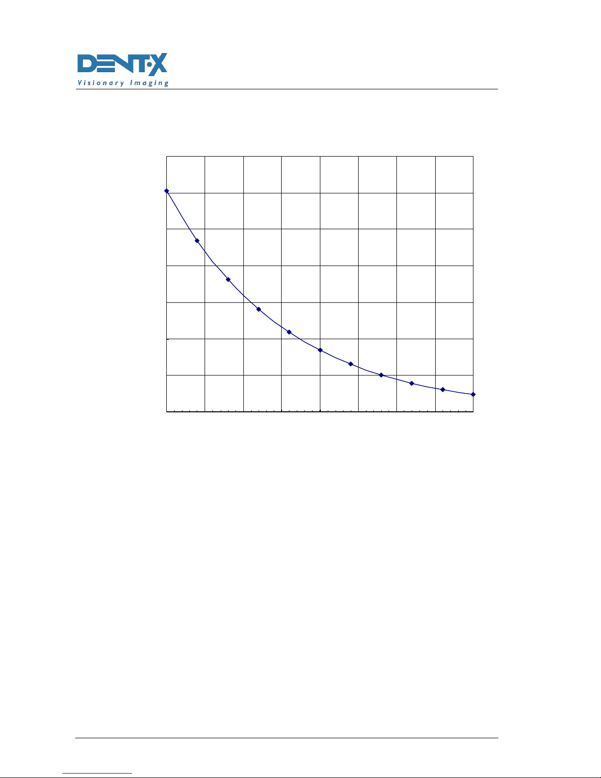
Cooling curve of tubehead
0
100
200
300
400
500
600
700
0 50 100 150 200 250 300 350 400
min
E( KJ )

SERVICE MANUAL
Technical features
(Rev. 0) RTG PLUS (120V)
4-7
4.3
4.34.3
4.3
Technical factors measuring method
Technical factors measuring methodTechnical factors measuring method
Technical factors measuring method
kVpThe peak tube potential is directly measured with a non invasive
kVp-meter, accuracy ±3kVp. When performing the measurement, make
sure that measuring probe is completely covered by the X-ray beam.
A direct measurement of the high voltage can only be carried out by
specialized technicians in a suitable testing laboratory as it requires
disassembling of the tubehead.
mA The output current is determined by measuring the voltage drop on a
resistor (1kΩ, 5%) using a digital multimeter, connected to the
corresponding plugs, as indicated on paragraph 7.4 (digital multimeter
set to VDC 20V, 1V=1mA).
tThe exposure times are determined by using a timer/counter, having an
accuracy of 0.1%, measuring the duration of part of the voltage applied
to the primary side of the tubehead, during the exposure phase.
Table of contents
Other DENT-X Medical Equipment manuals

Popular Medical Equipment manuals by other brands


Dräger
Dräger Babylog 1 HF Instructions for use

Shenzhen Mindray Bio-Medical Electronics
Shenzhen Mindray Bio-Medical Electronics DC-80S Operator's manual

Stryker
Stryker System 6 6206 Instructions for use

Bard
Bard X-Force N30 Instructions for use

miniland
miniland nasal care manual

LPG
LPG HUBER 360 EVOLUTION user guide