Seca 545 Series User manual

for seca 545
ServiceManual
5459021004
5459021124
5459021754
5459021774
5459021954
5459121004
5459121964
5459517744
5459521694
Pedal crank ergometer with electromagnetic eddy current brake, pulse detection
circuit and serial Interface RS232 for connection to ECG-machines. The
Ergometer is a medical product.
Valid as of:
29.06.2005
Variants:
Operation 17-10-05-237 c
Content:
Function diagram 30-36-00-249 b
Mechanics 30-36-00-284
Electronics 30-36-00-285
Pinning of connectors 30-36-00-283
Description of faults 30-36-00-286
Replacement 30-36-00-282 a
Calibration 30-36-00-287
Description serial Interface 30-36-00-275 b
spare parts 30-36-00-281 d
Description:
Service Manual Number
17-05-01-283-d
Manual number: 17-05-01-283-d


Service Manual
seca 545 Functional description of mechanical
equipment
25.02.99 Sievers Page 1 of 1 30-36-00-284
seca 545 Ergometer Edition: November 1998
Pedal crank ergometer with electromagnetic eddy current brake
Design
Steel frame as supporting structure, rests stably on the floor on four points.
Supporting points consisting of 2 rollers to allow the unit to be moved easily
and 2 adjusting caps for levelling out any unevenness of the floor.
Height-adjustable saddle with locking lever.
Turning handlebar with locking lever. Height-adjustable handlebar support with locking lever.
The handlebar support also carries the operating and display panel.
The testee drives the ergometer via the pedal crank.
The torque is transmitted in two stages to the disk flywheel of the eddy current brake.
In the first stage the torque is transmitted via a conventional 1/2 x 1/8 “bicycle chain
to an intermediate bearing with freewheel.
Transmission of the second stage via a toothed belt (HDT-8M).
A solenoid that works as an eddy current brake is mounted in a pendulum bearing.
A power sensor measures the brake power, a photosensor measures the speed.
From speed and brake power a braking torque is calculated which is altered by changing the
current in the solenoid. Due to this type of control the ergometer is independent of the torque
applied by the testee.
The ergometer comprises electronic circuits for open and closed loop control.

Service Manual
Ergometer 545 Description of the electronics
Description of the electronicsDescription of the electronics
Description of the electronics
10.03.1999 Panier Page 1 of 6 30-36-00-285
Ergometer electronic circuit description
( 08-01-25-211 )
Overview:
The pedal crank ergometer described below is used to subject the patient to strain with a
predetermined muscle power input and to measure the pulse frequency during this test. In order
to ensure these functions, electronics in SMD technology were developed which are described
below.
The ergometer electronics can be divided into three function blocks:
1. Digital section with µ-processor, serial interface, EEProm, reset circuit, ECG relay and several
digital control lines for controlling the display and the internal functions.
2. Sensor section with a pulse frequency sensor, a revolution sensor, a measuring amplifier with
DMS load cell for measuring the torque and a combined DA-AD converter in linear ramp
technology.
3. Power section with the power supply units for the eddy current brake ( 30V ), the digital
section ( 5V ) and the analog / sensor section with the power controller for the eddy current
brake.
Description of the digital section:
The µ-processor I9 is equipped with an integrated program memory in OTP, flash or mask
technology. It controls the display and the button functions for controlling the ergometer via the
digit and segment bus. Using the internal signals “pulse” and “speed” a software timer
determines the patient’s pulse frequency and the speed of the brake drum.
The remaining internal signals "CYCL", "SYNC", "MOMENT", "BSET" and "OSET" the DA-AD
are used to control the converter, to measure the actual torque, to set the torque setpoint and
the offset value for the measuring amplifier.
The parameters recorded during calibration such as friction losses, scale factor and various
internal parameters are stored in the EEProm I7.
In order to branch from the standard program to special modes a 4-position switch S1 is
provided. Presently it is used for setting the offset for the measuring amplifier ( S1.2 ) and for
switching to calibration mode ( S1.4 ).
Serial communication, e.g. with a control PC or the test bench, is performed by interface module
I6.
Description of the analog section:
a) The pulse frequency is measured by means of an infrared photosensor in the form of an ear
clip. The transmitter of the ear clip consists of an IR-LED which is supplied with a current of
30mA that is firmly set via R26.
The clip’s receiver is an IR-transistor which operates on a stabilized power supply T9. The
circuit’s operating point is controlled by the voltage at C6. The control voltage is generated
from the measuring signal via low-pass filter R24 / C6. The selected time constant of 100s is
long enough to ensure the measuring signal will not be corrupted. However, to allow fast
switch-on of the measurement, transistors T3 / T8 are provided to quickly correct the
operating point if the output voltage deviates by more than a base-emitter voltage from the
current voltage level at C6.
The measuring signal produced passes via the low-pass filter R18 / C4 to amplifier I5B, which

Service Manual
Ergometer 545 Description of the electronics
Description of the electronicsDescription of the electronics
Description of the electronics
10.03.1999 Panier Page 2 of 6 30-36-00-285
operates with open loop gain, and from there to the Schmitt trigger I5A.
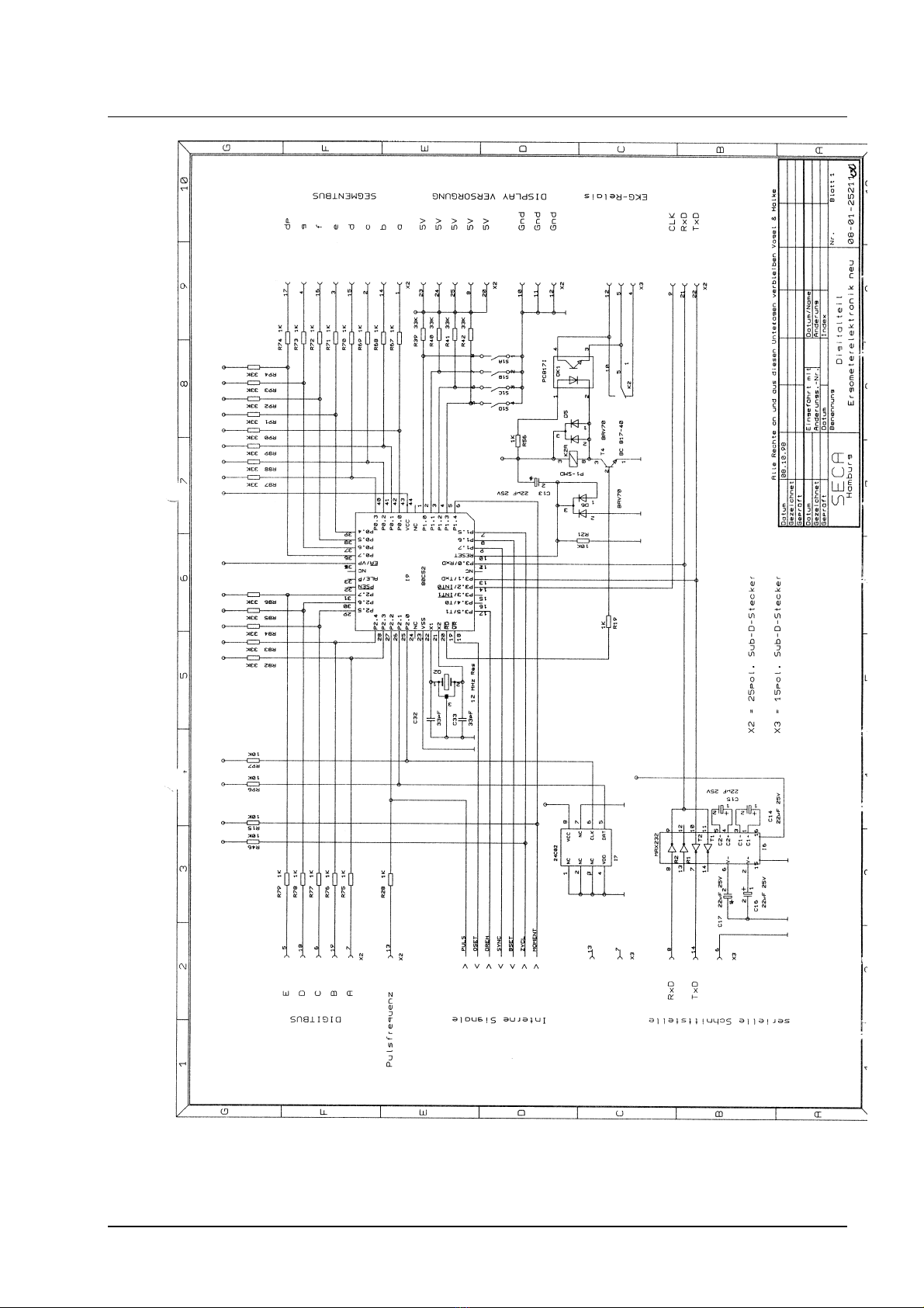
The resulting square-wave pulse signal "PULSE" is passed firstly to the pulse LED on the
display and secondly to the µ-P I9 for pulse frequency determination. For triggering the pulse
frequency measurement from an ECG plotter input X3.15 is available.
b) The speed is determined with a photosensor mounted to the ergometer brake. As the output
voltage of this photosensor is high enough, one transistor stage T12 is sufficient to form the
square-wave pulse. The output voltage is passed as a "SPEED” signal to I9 which determines
the speed.
c) The current braking torque is determined by means of the DMS load cell EF3. Its output
voltage is amplified by I4 and I10A and is passed as an analog signal "MANA" to the AD
converter and as an analog value to the torque controller I3. The measuring amplifier I4 is
adjusted to the offset parameters of the measuring cell used by means of resistors with wired
contacts R53 and R54. Coarse adjustment can be performed without taking into account the
spring pretension that will be set later, since the processor will make a fine offset adjustment
via R100 during the operation.
d) The central part of the AD/DA converter is the ramp generator consisting of I10C and I2A.
The actual measuring ramp starts at 9.5V and ends at 2.5V. The upper voltage limit is set by
the potential divider R2 and R3, the lower limit by R2 and R3//R10. Switch-over of the
reference voltages is effected by T2. The moment of switch-over is determined by I2A. The
ramp time is determined on the one hand by the two reference voltages and on the other
hand by the integrating capacitor C55 ( C3 ) together with R29 and R12. For the given
component characteristics a time of 0.45 s is used. The time for the reset ramp (start at 2.5V
and end at 9.5V) is set to 14.5ms via R12. By means of I12B, which is connected as an
inverter/level converter, the processor determines the measuring ramp time for temperature
compensation ("CYCL"). The analog switch I12A synchronizes the ramp with the µP
measuring timer ( "SYNC" ).
The analog switch I12C generates the analog setpoint for the torque controller ( "BSOLL" ).
Control is performed by the µP using ( "BSET" ). The control voltage for the measuring
amplifier offset is produced in the same way via I12D and the control signal "OSET".
Description of the power section:
a) The Mosfet T7 provides the power supply for the brake. It is controlled by square-wave pulses
at a frequency of approx. 200Hz. The pulse duty factor for these pulses can be adjusted in the
range 0 to 1 via torque controller I3A. This causes the brake current to vary between 0 and
approx. 3A, which is certainly sufficient for the required braking torques. I1B is a sawtooth
voltage generator for generating the 200Hz control voltage. The sawtooth amplitude is
approx. 5V. The variable pulse duty factor for the control voltage for the brake solenoid is
generated by comparing this sawtooth voltage with the output voltage of torque controller I3A
( comparator I1A ). Torque controller I3A is an IT1 type with an integration time constant of
0.22s. Selecting this time constant allows the torque controller to almost completely adjust the
specified torque within a DA interval. R17 and C1 are used to optimize the controller
characteristics. T11 and T10 limit the maximum controller stroke to the amplitude of the
200Hz sawtooth to prevent the I-controller “overshooting” and producing detrimental delay
times in the control loop. I3B is an inverter for the torque setpoint ( "BSOLL" ). It has an
additional time constant C54, R59 and thus ensures smooth transitions if the torque setpoint
changes suddenly. Due to the analog controller the settling time for the required braking
torque can be almost freely controlled by the processor ( > approx. 1s ).

Service Manual
Ergometer 545 Description of the electronics
Description of the electronicsDescription of the electronics
Description of the electronics
10.03.1999 Panier Page 3 of 6 30-36-00-285
b) The power supply unit produces the three required ergometer operating voltages: Power,
VCC, VCC2+.
“Power” supplies the current for the brake and for the two other power supply units. Fuse
protection is provided by fuse 4AT. VCC’s operating current can be as high as 800mA due to
the LED display. Consequently, a low loss switching controller I11 is used here. As a result of
a suitable layout and the selected components the voltage ripple is approx. 80mV, which,
among other things, keeps interfering radiation low. VCC is fuse protected by an SMD fuse
1AT.
As the current is only approx. 40 mA, the analog measuring circuit is supplied by an analog
voltage regulator I8. High accuracy or temperature stability is not required since all measuring
voltages are derived from this voltage and fluctuations are thus compensated.
The ergometer is electrically isolated from the mains by a conventional mains transformer. On
the primary side the transformer is protected by a two-phase fuse. An interference filter
prevents interference being injected into the circuit.

Service Manual
Ergometer 545 Description of the electronics
Description of the electronicsDescription of the electronics
Description of the electronics
10.03.1999 Panier Page 4 of 6 30-36-00-285

Service Manual
Ergometer 545 Description of the electronics
Description of the electronicsDescription of the electronics
Description of the electronics
10.03.1999 Panier Page 5 of 6 30-36-00-285

Service Manual
Ergometer 545 Description of the electronics
Description of the electronicsDescription of the electronics
Description of the electronics
10.03.1999 Panier Page 6 of 6 30-36-00-285


Seca
Page
1(2)
Description of faults
02.12.99- Meyer
30-36-00-286
Please read the operating instructions carefully to make sure that ergometer malfunctions
are not caused by operation faults. Should any faults occur, the following table will help
you to identify the cause of the fault.
Mechanical faults
Fault description
Possible
cause Remedy
Unsteady running,
noise, etc. •Chain drive not
correctly
adjusted
•Open the ergometer and adjust the chain
•Belt drive not
correctly
adjusted
•Open the ergometer and adjust the belt in accordance with the
replacement instructions
•Bottom bracket
bearing defectiv
•Check bottom bracket bearing and replace if necessary
•Pedal cranks
loose, knocked
out
•Check that the cranks are fixed properly to the bottom bracket
bearing pins, replace pedal cranks and / or bottom bracket
bearing if necessary
Pedals freewheeling •Power
transmission
interrupted
•Check drive (chain and belt), replace defective parts if
necessary, readjust drive
Pedals are blocked •Power
transmission
blocked
•Check drive (chain and belt) for jammed chains and / or belts,
readjust drive
Electrical / electronic faults
Fault description
Possible
cause Remedy
Ergometer not
working •Mains cable not
properly
plugged into
inlet connector
•Check connections and mains cable, replace mains cable if
necessary
•Primary mains
fuse defective •Check 2 (primary) fuses, replace if necessary
•Secondary
mains fuses
defective
•Open ergometer, remove casing, check visible type fuse 4 AT
and SMD fuse 1 AT, replace if necessary
•Rectifier or
transformer
supply lines
defective
•Open ergometer, remove casing, check voltage on the rectifier
supply lines / transformer output, replace ergometer power
supply unit board if necessary
Display not working
or not complete
(segment fault)
•Plug-in
connection
interrupted
•Check plug-in connection and cable between ergometer and
display, replace display if necessary
No pulse display •Ear clip not
correctly
attached or not
working
•Wipe ear lobe and ear clip, check ear clip plug-in connection,
replace ear clip if necessary

Seca
Page
2(2)
Description of faults
02.12.99- Meyer
30-36-00-286
Buttons / display not
working •Display or
display cable
defective
•Replace display
Fault description
Possible
cause Remedy
Fault message Err X
on speed display •Fault in the
electronics •Switch ergometer off and on again, if the fault message is
displayed again = service required -> replace ergometer
electronics
No communication
with ECG plotter •Interface cable
defective •Check interface connection and cable assignment
No braking effect
during the operation
•Brake or
actuation
defective
•Check brake connections, replace electronics

Service Manual
seca 545 Replacement instructions
25.07.00 Reinhold 2.Page of 5 30-36-00-282
Index a
seca 545 Ergometer Edition: November 1998
Edition: November 1998Edition: November 1998
Edition: November 1998
1. Remove casing / outer parts.
(see drawing page 3)
1.1 Disconnect all cables.
1.2 Turning handlebar (1).
Unscrew the clamping lever (2) and pull out the clamping element (3).
Pull the handlebar rod and the spacer cap (4) out of the guide tube.
1.3 Saddle pillar (5).
Unscrew the clamping lever (6) and pull out the clamping element (7).
Pull the saddle rod together with the spacer cap (8) out of the guide tube.
1.4 Power supply casing (9).
Release the fixing screws (10) on the right-hand power supply unit casing and remove the
casing half.
Release the stay bolt (11) on the left-hand power supply unit casing and remove the
casing half.
1.5 Pedal cranks (12).
Unscrew the plastic cap (13), release the hex screw (14) and take off the pedal cranks.
1.6 Side casing (16).
Release the cheese head screws (17r) on the right-hand side panel and remove the casing parts,
the right-hand side panel and the front (18) and rear (19) ornamental foils.
Release the two top cheese head screws (17l) on the left-hand side panel
and remove the side panel.
2. Replacing the modules.
(ergometer with electromagnetic eddy current brake 35-03-03-007 til 09/99 see drawing page 4)
(ergometer with electromagnetic eddy current brake 35-03-03-011 from 10/99 see drawing page 5)
2.1 Operating panel.
Replacement without instructions.
2.1 Power supply unit with mainboard, calibrated (21).
Start with steps 1.1,1.2 and 1.4 to 1.6.
Remove the electronics (23) cover plate; to do so, release the self-tapping screws (24).
Unsolder the cable connections (25) to the eddy current brake (26) and the revolution
counter (27).
Unhook the tie rod (28) between power sensor (29) and eddy current brake (26).
Release the hex nuts (30) on the clamping plate (31).
Pull the power supply unit up over the handlebar rod guide tube and pull it off.
2.3 Mainboard complete for ergometer power supply unit (23).
Start with steps 1.1, 1.2 and 1.4.
Remove the electronics (23) cover plate; to do so, release the self-tapping screws (24).
Unsolder the cable connections with the exception of the power sensor (29).
Release the cheese head screws (33) on the power sensor fixing device.
Unhook the power sensor (29) from the tie rod (28).
Release the fixing screws (34) on the board and remove the electronics together with the
power sensor.

Service Manual
seca 545 Replacement instructions
25.07.00 Reinhold 2.Page of 5 30-36-00-282
Index a
2.4 Eddy current brake (26).
Start with steps 1.1 and 1.4 to 1.6.
Unsolder the cable connections (25) to the power supply unit (21).
Release the toothed belt tension (35).
Unhook the tie rod (28) and the spring (36).
Pull the protecting caps (37) off the hex nuts (38), release the hex nuts.
Pull the eddy current brake (26) slowly forwards and out and remove the revolution
counter (27), be careful with the cable connection between the revolution counter and
the electronics.
After fitting the eddy current brake tension the toothed belt (44) as described in section 2.17.
2.5 Revolution counter (27).
Start with steps 1.5 and 1.6, but only remove the left-hand pedal crank and side panel.
Unscrew the revolution counter board from the holder (39).
Unsolder the cable connections from the board.
2.6 Bottom bracket bearing (40).
Start with steps 1.5 and 1.6.
Release the chain tensioner (41) and remove the chain (42).
Release the hex nuts (43) on the bearing bush.
Pull the bottom bracket bearing to the left and over the toothed belt (44).
2.7 Intermediate bearing (45) and / or freewheel (46).
Start with steps 1.5 and 1.6.
Slacken the toothed belt (35).
Release the hex nuts (47) on the axle, pull off the chain tensioner (41) and
remove the intermediate bearing.
After fitting the intermediate bearing tension the toothed belt (44) as described in section 2.17.
2.8 Chain tensioner (41).
Start with steps 1.5 and 1.6, but only remove the right-hand pedal crank and side panel.
Only release the outer hex nut (47) on the intermediate bearing axle (45).
Pull off the chain tensioner.
2.9 Bicycle chain (42).
Follow the instructions in section 2.8.
2.10 Toothed belt (44):
To replace the toothed belt, the eddy current brake must be removed as described
in section 2.11.
Toothed belt tension:
Tension the toothed belt by adjusting the intermediate bearing using the tensioning device.
The toothed belt should be so taut that it will sag by 7 - 8 mm when a test load of 35 N is applied at
half the length of the belt. Make sure the intermediate bearing is screwed tight before applying the
test load.
2.11 Interference filter / circuit breaker (48), harness for main switch (49) and transformer (50).
Start with steps 1.1 and 1.4.
Unsolder the cables from the relevant componenets and replace the module.
3. Assemble in reverse order.


Service Manual
Medical pedal crank ergometer Adjustment instructionsAdjustment instructions
Model 545
11.03.1999 Panier Page 1of 10-36-00-287
Adjustment instructions for the seca pedal crank ergometerAdjustment instructions for the seca pedal crank ergometer
Model 545Model 545
Calibration during maintenance workCalibration during maintenance work
The seca pedal crank ergometer is a medical product, class IIA and is thus subject to the legal
regulations regarding medical pedal crank ergometers. One particular maintenance job stipulated is
checking the ergometer for observance of the fault tolerance limits every two years (see the section on
Technical data in the Operating instructions).
The ergometer must be tested dynamically, i.e. it is driven at speeds within the working range and the
patient’s muscle power input is determined using suitable test equipment and checked against the fault
tolerance limits given below. Static calibration is no longer permitted.
Seca has special service partners who perform the dynamic tests on the ergometer. Please contact our
Customer Service for assistance.
Fault tolerance limits
acc. to EO15-12:
5% of the power output
or 3 W
Fault tolerance limit vs
power
Working range of the
braking torque control
system acc. to PTB-
A15.12 / 4.2
Speed vs power

Description of the RS232 interface for Ergometer 545
SECA/EE/GER Page 1of 330-36-00-275 Index B
1. RS2321. RS232 interfaceinterface formatformat
- V24 level
- baud rate : 1200 baud
- 8 data bits
- 1 start bit
- 1 stop bit
- no parity bit
2. RS2322. RS232 interfaceinterface protocolprotocol
2.12.1 OverviewOverview
Two different protocols are used, which are described in the following sections.
The following variants of the STRESS protocol exist:
•545 9021 009 with the software 08 06 15 238 : 179SV1
•545 9021 759 with the software 08 06 15 238 : 179SV1
The following variants of the status protocol exist:
•545 9021 129 with the software 08 06 15 236 : 179GB1
2.2 STRESS2.2 STRESS protocolprotocol
Using this protocol the ergometer continuously sends data blocks of 6 bytes (FF, FF, ph,
pl, sh, sl). Their meaning results from grouping 16 bit data in accordance with the
following table:
MSBMSB LSBLSB ExplanationExplanation CommentsComments
FF FF Start ID
ph pl Power setpoint P = (ph * 256 + pl) W / 10
sh sl Speed S = (sh * 256 + sl) / 10
The ergometer can receive the following commands / data (16 bits):
MSBMSB LSBLSB FunctionFunction CommentsComments
FF 00 Mode ON Operating panel not active
FF FF Mode OFF Operating panel active
Hi Lo Power setpoint * 10 P = (Hi * 256 + Lo) W / 10
The power setpoint can only be changed via the serial interface if "Mode ON" is active.

Description of the RS232 interface for Ergometer 545
SECA/EE/GER Page 2of 330-36-00-275 Index B
2.3 Status2.3 Status protocolprotocol
The ergometer sends the following data every second:
Byte - no. Value
01 Power setpoint LSB
02 Power setpoint MSB
03 Actual power LSB
04 Actual power MSB
05 Speed LSB
06 Speed MSB
07 Minutes
08 Seconds
09 Linearity factor LSB
10 Linearity factor MSB
11 Friction factor LSB
12 Friction factor MSB
13 Braking power register LSB
14 Braking power register MSB
15 A/D ref cycle time LSB
16 A/D ref cycle time MSB
17 Calibration speed LSB
18 Calibration speed MSB
19 DMS refresh reg. LSB
20 DMS refresh reg MSB
21 A/D cycle time LSB
22 A/D cycle time MSB
23 Strain gauge signal A/D value LSB
24 Strain gauge signal A/D value MSB
25 Strain gauge zeropoint LSB
26 Strain gauge zeropoint MSB
27 Pulse period LSB
28 Pulse period MSB
29 Working memory L byte
30 Working memory M byte
31 Working memory H byte
32 Training value
33 Segment info time and power stage
34 Strain gauge offset
This manual suits for next models
9
Other Seca Medical Equipment manuals