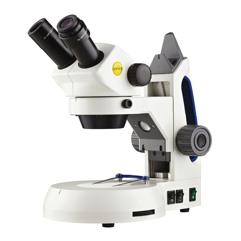
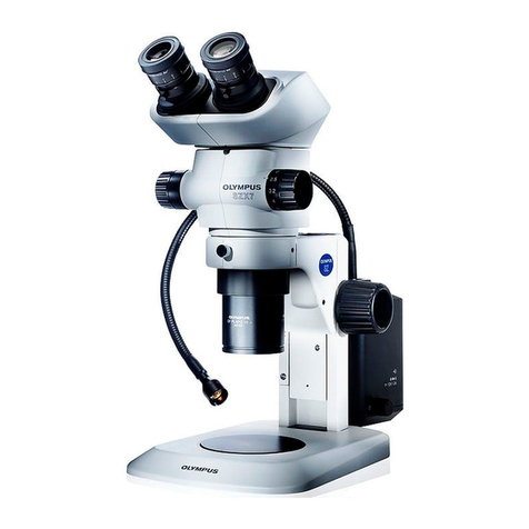
Denville Scientific MZ180 Series User manual

MZ180 Series
ZOOM STEREO MICROSCOPE
USER’S MANUAL
Denville Scientific Inc.
P. O. Box 4588
Metuchen, NJ 08840-4588
908-757-7577 FAX 908-757-7751
www.denvillescientificcom

INTRODUCTION:
The MZ180 Series zoom stereo microscopes adapt multifunction design and excellent
manufacturing technology to make the outstanding products. These instruments have
been built to offer reliable performance at a competitive price. The superb quality and
affordable price make the MZ180 Series ideal instruments for a variety of industrial,
medical, veterinary, educational or special applications.
SHIPPING:
The unit is shipped in a Styrofoam container, which is placed, into a cardboard box.
Examine the shipment for evidence of abuse and retain all packing material until the unit
has been tested. If damage has occurred, contact the carrier immediately. Your warranty
specifically excludes damage during shipping.
UNPACKING:
Carefully open the carton and verify that the shipment is complete. If necessary, refer to
your purchase order for the microscope configuration. Assure that no hidden damage has
occurred. If any parts are missing, please call Denville Scientific customer service at
800-453-0385 or e-mail us at info@Denville scientificsci.com. Please be ready with the
serial #, date of purchase and name of supplier.
ASSEMBLY:
Place the instrument on a stable, clean desk with access to an electrical outlet. Unless
otherwise specified, please follow these general installation directions: (for model
MZ156 stereo microscope with boom stand, please refer to the boom stand installation in
this manual).
1. Put the stand on a smooth and stable surface or working table.
2. If you have purchased a unit with a diascopic base, put the diascopic base on the
table first and then attach the stand. There are two locking screws, one in the
front underneath the diascopic base and on in the back with the transmitted light
adapter. Tighten the two screws so that the diascopic base is securely locked onto
the stand.
3. Loosen the zoom body locking screw on the focusing mount where the zoom
body goes. Put the zoom body into the mount.
4. Rotate the body to the direction you want the eyepiece tubes to face. Lock the
body with the locking screws.
5. Insert the eyepieces in the eyetubes of the zoom body.

6. IMPORTANT: Before you plug the power cord into an electrical outlet, make
sure that the output voltage of the outlet matches the input voltage requirement of
the instrument. Then insert the power plug into the electrical socket.
BOOM STAND INSTALLATION:
Boom stand includes base, vertical pole, fitting block, locking ring, horizontal pole with
5/8” hole at end. An Allen key is supplied for tightening universal arm or 25mm post to
the horizontal pole. The 25mm post is needed for focusing mount.
For model MZ155 microscope package, universal arm is included with boom stand.
MZ156 microscope package include boom stand, 25mm post and focusing mount.
Following the steps below to set up the boom stand:
1. First put the heavy metal base on a stable surface. Install the vertical pole into the
base (thread-on) and remove the cap on the other end of the vertical pole.
2. Slide the locking ring onto the vertical pole and lock it in place about half way
down the pole.
3. Put the fitting block onto the vertical pole 2 inches above the locking ring and
lock the fitting block with the knob.
4. Slide the horizontal pole into the fitting block tight it with the locking knob.
5. Put back the cap back onto the top of the vertical pole.
6. The vertical pole can be locked to the base by tightening the screw on the back
side of the base.
7. If universal arm is used, insert the 5/8” knuckle of the universal arm into the end-
hole on the horizontal pole. Lock it with Allen key.
8. If 25mm post and focusing mount are used, first insert the 25mm post into the
end-hole and lock it. Then slide focusing mount into the 25mm post. Lock the
focusing mount with the locking knob on back of the focusing mount.
Boom Stand
(showed Universal Arm and 25mm Post)
(1) Heavy Metal Base
(2) Vertical Pole
(3) Locking Ring
(4) Fitting Block
(5) Lock Knobs
(6) Horizontal Pole
(7) Universal Arm
(8) Allen Key
(9) 25mm Post

OPERATION:
PROCEDURES OF STAND FOCUSING ADJUSTMENTS
1. Place the specimen you wish to view and examine. If you have ordered an
illumination stand, plug the power cord to the proper power outlet. If the
specimen is opaque, you need to use black/white stage plate. Select one side of
the black and white plates to give you the best contrast.
2. Use the focusing knob to locate and focus on the surface of the specimen. There
are two kinds of stands. One is pole-type and another is solid stand. If you have
pole-type stand, you may need to slide the whole focus assembly up and down on
the pole by loosening the locking screw. After you have set the focus assembly at
the most proper position for your application, tighten the locking screw.
PROCEDURE OF ZOOM BODY ADJUSTMENTS AND SETTING
1. Interpupillary Adjustment: Adjust the interpupillary distance until you get a single
non-overlapping image by rotating the binocular eyepiece tubes to adjust the
interpupillary distance.
2. Focusing: The Stereo microscope allows the observer to see the object’s image in
three dimensions. This means the viewer is able to perceive height and depth of a
specimen. To do this, the images coming from the binocular eyepieces must be
formed in a single image for the observer. After the interpupillary distance has
been properly set, the eyetube diopters need to be adjusted. This adjustment
allows the focus to remain sharp in both eyepieces through the whole zoom range.
Please follow the procedures to set the zoom body:
A) Rotate the zoom body to the highest power (4.5x). Set the diopters on
both eyepiecetube to “0”. Then use the focusing knobs on the microscope
to focus sharply on the specimen.
B) Rotate the zooming mechanism to get the lowest power (0.7x). DO NOT
TOUCH the focusing knob on the stand.
C) Look through the right eyepiece; rotate the eyetube until the image is
precisely in focus (the diopter is now properly set). Do the same for the
left eyepiece to set the diopter.

D) Bring the zoom body to the highest power again. If the image is not in
sharp focus, adjust the focusing mechanism to bring the specimen in
focus. The image should remain sharp throughout the entire zoom range.
TENSION ADJUSTMENT OF FOCUSING KNOB
The tension of the focusing knob have bee properly pre-adjusted. However you may
readjust the focusing tension of the focusing knob to your desired level. Follow the
procedures below:
Increase Focusing Tension:
To increase the focusing tension, hold the left knob with your left hand; use your
right hand to turn the right knob clockwise. To check the tension, release your left
hand and rotate the knob with either or both hands in the same direction. If it is
not tight enough, repeat the above step until the proper tension is set.
(Note: If the tension is too tight, please follow the “Decrease Focusing Tension”
procedure to adjust it)
Decrease Focusing Tension:
To decrease the focusing tension, hold the left knob with your left hand; use your
right hand to turn the right knob COUNTER clockwise. To check the tension,
release your left hand and rotate the knob with either or both hands in the same
direction. If it is not loose enough, repeat the above step until the proper tension is
set.
(Note: If the tension is too loose, please follow the “Increase Focusing Tension”
procedure to adjust it)
MAINTENANCE AND CARE:
GENERAL:
1. During both operation and storage, avoid airborne contaminants and moisture.
2. Protect the instrument with a dust cover when it is not in use.
3. DISCONNECT the power cord before replacing the lamp. Allow the lamp to
cool before replacing it.
CLEANING:
1. Use filtered air and a camel hair brush to remove dust particles from the optical
surfaces.

2. For routine cleaning, use a clean cotton swab and lens cleaner.
3. For difficult spots or stains, use a lens cleaning solution designed for coated optics
and a clean lint-free cloth or lens tissue.
MZ180 Series Microscope
1
2
5
8
9
Model MZ155 (shown)
3
4
6
7
10

1
Eyepiece
6
Focusing knobs
2
Eyepiece tube with Diopter adjustment
7
Top illumination
3
Zoom body
8
Stage clips (Specimen holder)
4
Stand
9
Stage plate
5
Zoom knobs
10
Base illumination
Table of contents
Other Denville Scientific Microscope manuals


