Olympus BX-FLA User manual

INSTRUCTIONS
BX-FLA
REFLECTEDLIGHT FLUORESCENCE
ATTACHMENT
This instruction manual is for the Olympus BX System Attachment Model BX-FLA. To ensure the
safety and obtain optimum performance and to familiarize yourself fully with the use of this attachment,
we recommend that you study this manual thoroughly before operating the microscope system.
Retain this instruction manual in an easily accessible place near the work desk for future reference.
IlllllllIIIllllllIll1IllIll1II11lllllIIIII1
AX5837

BX-FLA
This unit employs a UIS (universal infinity system) optical design, and should be used only with
UIS eyepieces, objectives, and condensers. Less than optimum performance may result if
inappropriate accessories are used.
L
J
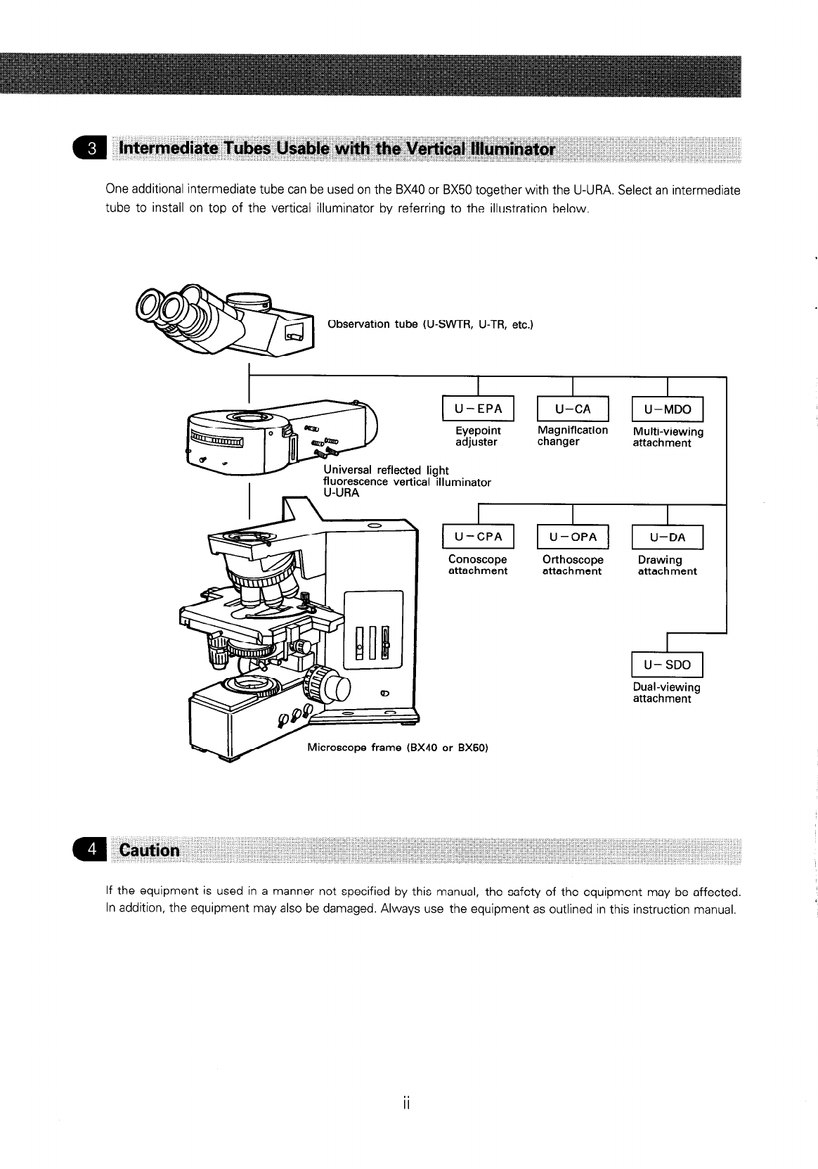
The universal reflected light fluorescence vertical illuminator features interchangeable cubes to employ excitation
light of different wavelengths. If also allows combined or alternating reflected light fluorescence and transmitted
white light observations.
1. Reflected light fluorescence + transmitted light phase contrast.
2. Reflected light fluorescence + transmitted light Nomarski differential interference contrast.
3. Reflected light fluorescence + transmitted light brightfield or darkfield.
By mounting standard cubes for reflected light observation, the following observation methods become possible.
1. Reflected light brightfield/darkfield observation.
2. Reflected light Nomarski differential interference contrast.
3. Reflected light simple polarized light observation.
This instruction manual consist of two parts: I. Reflected Light Fluorescence Observation and II. Reflected
Light Observation Modes. Use these headings to find the relevant page with the instructions for the particular
observation mode.
a
Getting Ready
I. A vertical illuminator is delicate. Handle it carefully, and avoid jolts.
2. The high pressure mercury burner used in the unit should be a USH102 (mfd. by Ushio Electric). The
halogen lamp used in the unit should be a 12V, IOOWHAL halogen bulb (Philips 7724).
3. Verify that the burner is installed correctly and that all cords are properly connected.
4. The ultraviolet rays emitted by the burner are harmful. Be sure to use a UV protective shield with the unit.
(See page 9.)
5. Do not open the lamp housing while the burner is turned on or for at least 10 minutes after it is turned
off. The lamp housing inside is extremely hot and will cause injury if touched. (See page 11.)
6. The power supply unit contains high voltage components. Do not attempt to disassemble it.
7. Always ground the unit.
8. Before opening the lamp housing for replacement of the burner or other, turn off the main switch and
unplug the power output connector from the power unit. Wait for more than 10 minutes for the burner and
lamp socket to cool down.
9. Before plugging in the mains power cord, make sure that the main switch on the power supply unit is
turned off.
1. Clean all glass components by wiping gently with gauze. To remove fingerprints or oil smudges, wipe with
gauze slightly moistened with a mixture of ether (70%) and alcohol (30%).
A Since solvents such as ether and alcohol are highly flammable, they must be handled carefully. Be
sure to keep these chemicals away from open flames or potential sources of electrical sparks - for
example, electrical equipment that is being switched on or off. Also remember to always use these
chemicals only in a well-ventilated room.
2. Do not disassemble any part of the attachment.
3. The burner has a service life period of 200 hours. When the hour counter on the power supply unit indicates
200 hours, replace the burner with a new one. (See page 8.)
4. When not using the unit, cover it with the dust cover provided and store it in a dry place to prevent mold
formation.
5. If a dichroic mirror cube is not to be used for a while, place it in its container and store it in a safe place.

One additional intermediate tube can be used on the BX40 or BX50 together with the U-URA. Select an intermediate
tube to install on top of the vertical illuminator by referring to the illustration below.
Observation tube (U-SWTR, U-TR, etc.)
Eyepoint Magnification
adjuster changer
rsal reflected light
fluorescence vertical illuminator
U-URA
Conoscope
attachment
w
Microscope frame (BX40 or BX50)
+l
U-OPA
Orthoscope
attachment
Multi-viewing
attachment
U-DA
Drawing
attachment
Dual-viewing
attachment
If the equipment is used in a manner not specified by this manual, the safety of the equipment may be affected.
In addition, the equipment may also be damaged. Always use the equipment as outlined in this instruction manual.

BX-FLA

The design of reflected light fluorescence microscopes features dichroic mirrors which direct the excitation light
through the objective, to the area of the specimen, thus providing efficient illumination. (Fig. 1)
Eyepiece
II
I
I
I
> Objective
I’
Specimen 4%
- Excitation light
-----+ Emitted light
Crossover
The spectral characteristics of the dichroic mirror when it is positioned
at an inclination of 45” to the optical axis of incident light is shown in
Fig. 2. Because a cross-over exists between transmittance and reflect-
ance, it is necessary to use an appropirate combination of exciter and
barner filters in conjunction with the dichroic mirror. This is necessary
to achieve a good contrast image through fluorochrome excitation in
the specimen, at the desired wavelength.
When the dichroic mirror is inclined 45” to the optical axis of incident
light, it reflects the excitation light towards the objective, and passes
unwanted wavelengths.
When the specimen is irradiated by the excitation wavelength, it emits
a visible longer wavelength corresponding to Stoke’s law. The barrier
filter mounted between the objective and eyepiece blocks out unwanted
wavelengths providing a black background.
1 0

Universal reflected light
fluorescence vertical illuminator
I I
Mercury lamp housing
Power supply unit
BX-series microscope
I
I
I
Universal condenser
0
2

1 A. Universal Reflected Light Fluorescence Vertical Illuminator
Light excluding
shutter
Filter slider
(Another is on opposite side.)
\\ Slider insertion slot
1 B. Cube
Removable index mark * Combine with dichroic mirrors, barrier filters and exciter filters
as appropriate for the desired excitation method.
Do not disassemble the cube.
3
4

) C. Fluorescent Light Source
l
Mercury Burner Lamp Housing
Burner centering knob
Burner Socket
l
Power Supply Unit
Burner ON LED
%Main switch
AC receptacle output
connector
0
4

0 To assemble the BX40 or BX50, consult the instruction manual pertaining to the BX40 or BX50 microscope.
k When assembling the units, make sure that all parts are free of dust and dirt, and assemble the parts
in the sequence indicated by the numbers in the illustration below.
Eyepiece
Observation tube
nrversal reflected
orescence vertic
UV protective shield
Light excluding slide
Microscope frame
*See paragraphmon page 16 regarding objectives to use for different observation methods.
+ For selection of the appropriate cubes for the observation, refer to Sectionnon page 17.
5
l

BX-FLA
Fig. 1
Fig. 2
Fig. 3
Fig. 4
a
Mounting the Cubes
{Figs. 1,2,31
0 See paragraph
q
on page 17 regarding which cubes to use for different
observation methods.
1. Loosen the clamping screw 0 at the right of the vertical illuminator
using the Allen screwdriver provided with the microscope frame.
(Fig. I)
2. Pull out the turret in the direction indicated by the arrow, then invert
the turret so that the cube dovetail mounts @ point upward.
(Dummy plates are mounted in three of the four cube positions. When
you wish to use only one cube, mount it in the empty position. When m A
using two or more cubes, loosen the clamping screw @ and remove
the dummy plate(s) by pulling in the direction indicated by the arrow, 5
and then mount the actual cube(s) instead.) Y
3. Hold the cube to be mounted with its index side facing upward and
slide it all the way onto the dovetail mount. Next, be sure to tighten
the cube clamping screw @Iimmediately. (Tighten all four cube clamping
screws.)
4. Remove the cube’s magnetic index sticker @ and affix it to the
corresponding turret position. (Fig. 2)
Ir Use a sharp object such as the tip of a ballpoint pen or
mechanical pencil to lift the cube’s magnetic index sticker.
Ir Move the cube’s magnetic index sticker (WU, NU, etc.) to the
corresponding A, B, C, D position on the turret. The positioning
indices @ A, B, C, and D on the cube dovetail mount corre-
spond to the A, B, C and D indices @ on the turret.
a Mounting thle Turret
(Fig. ‘1)
Insert the turret into the vertical illuminator housing and tighten the
lock screw @ while pushing the turret inward as far as it will go.
*When performing fluorescence observation, make sure to mount
dummy plates in the empty cube positions. For transmitted light
observation only, it is unnecessary to mount the dummy plates.
However, be sure to tighten the cube clamping screws when no
dummy plate is mounted. If the screws are left loose, the screw
heads may obstruct turret rotation. Mount the dummy plate by
reversing the procedure described in m-2.
Q
‘lVl-ousrti,~g.the Univqwl Fluorescenc;e
tirrEtrtic;afIlluimihatar (Fig 4)
Remove the two plugs from the top of the microscope frame and the
vertical illuminator. Then use the provided Allen screwdriver to clamp the
vertical illuminator to the microscope frame (two locations).
0
0 0

Fig. 5
7
Fig. 6
Fig. 7
Fig. 8
a
1
(Figs,
5,&T,
8,9,la,l1)
Mounting
the
Mercury Burner
I. Remove the burner socket clamping screw @ using the Allen screw-
driver provided with the microscope.
2. Remove the socket from the lamp housing as indicated by the
arrow. (Fig. 5)
3. Loosen the burner clamping screws @ and @ (Fig. 6) and remove the
securing post. (For burner replacement, remove the used burner.)
4. With the + pole of the mercury burner @ facing downward, insert the pole
into the opening and tighten the burner clamping screw 0. Then loosen
the burner clamping screw 0. Insert the pole (marked UP) of the burner
into the opening and tighten the burner clamping screw @ (Fig. 6)
* Use only a USH102 burner (mfd. by Ushio Electric).
+ Be careful to avoid getting fingerprints or dirt on the burner. To
remove fingerprints or other oils, moisten the cloth slightly with a
3 : 7 mixture of alcohol and ether, or with xylene.
* Dust or other contaminants left on the bulb sulface may lead to the
appearance of dark spots in the field of view during observation.
Ir At this point, mount the collector lens.
+ In order to avoid possible damage to the burner, the collector lens
can only be installed or removed while the socket and lamp
housing are removed.
Mounting
the Collector Lens
1. Align the collector lens positioning groove @with the pin inside the lamp
housing, pull up the collector lens focusing knob 0, and slide the
collector lens into the lamp housing as far as it will go. Then, return the
collector lens focusing knob @ to its original position. At this point, check
that the collector lens can be moved back and forth by turning the
focusing knob 0. If not, adjust the position of the collector lens by hand
so that it will click into its proper position.
2. Tighten the collector lens retaining screw 0. (Fig. 7)
Note: Ifthis retaining screw is not tightened firmly, optimum illumina-
tion performance will not be obtainable.
3. Reattach the socket to the lamp housing by reversing the procedure
outlined in ml) above. (Fig. 8)
4. Tighten the socket clamping screw @ with the Allen screwdriver. (Fig.5)
* A click is heard, when the clamping screw @ is tightened. This
sound indicates that the safety interlock switch is functioning
properly.
* If you accidentally loosen the clamping screw while the burner is
operating, the interlock switch turns off the burner. In order to
restart the burner, you must turn off the main switch on the
power supply unit. Then pull out the power cord (as a safety
precaution if you open the lamp housing) and wait for about 10
minutes, then retighten the clamping screw and turn the main
switch back on again.
/ 0

.
Fig. 9
Fig. 10
Fig. 11
Resetting the Burner Hour Counter
I. Press the center of the reset button 0 (Fig. IO) on the power supply
unit’s front panel @ (Fig. 9) to reset the burner life indicator to 000.0.
0 The indicator shows elapsed time in hours, For safety’s sake, replace the
burner when the indicator counts 200.0 hours.
* Make sure that the indicator is properly reset to 000.0. The burner
may not start if the indicator is not properly reset.
Mercury Burner Replacement
1. In order not to impair the safety of the equipment, replace the
burner when it has been used for 200.0 hours. The burner may
crack if used beyond the specified life time.
2. Before replacing the burner, wait at least 10 minutes after turning
the burner off. Before removing the burner, confirm that the
main switch on the power supply unit is OFF, and unplug the
connecting cord plug from the output connector on the power
supply unit. Refer to page 7 for details on replacement procedure.
3. After replacing the burner, reset the burner life time hour counter
to “000.0” as outlined above.
1. Insert the collector lens portion 0 of the mercury lamp housing into
the vertical illuminator and push inward until it clicks in place.
2. Tighten the collector lens clamping screw @ with the Allen screwdriver.
0
8

7
I
u
Install Conversion Lens (option)
0
dl> I
When brighter illumination is required, use the optional U-UCV @
conversion lens. To install the conversion lens, insert it between the
vertical illuminator and the lamp housing and fasten it with the two
clamping screws. (Fig. 12)
* Light intensity in the periphery of the viewfield may be slightly
reduced in super widefield observation (FN26.5).
Fig. 12
\
@--
Fig. 13
1. Verify that the voltage and frequency of the mains outlet match the
requirements indicated on the name plate Q on the power supply unit.
(IOOV systems can be used with voltages in the IOO-120V range and
frequencies of 50-60 Hz.)
2. Plug the connecting cord into the power supply unit’s output connector
0.
3. Connect the power cord to the AC receptacle @ on the power supply
unit, then plug the other end of the cord into an AC outlet.
A Connect the power cord correctly and ensure that the ground
terminal of the power supply and that of the wall outlet are properly
connected. Ifthe equipment is not grounded, Olympus can no longer
warrant the electrical safety and performance of the equipment.
\
Align the UV protective shield’s key holes @ over the guide pins @
and the mountrng pin @ and lower the shield into place.
Fig. 14
\
0 When performing fluorescence observatron with a low-power objective,
image clarity may be reduced by light reflected from the condenser. If
this happens, use the light excluding slide.
@ To mount the light excluding slide 0, insert it into the space underneath
the stage. When switching between transmitted light observation
methods (phase contrast observation, Nomarski observation, etc.), set
the slide on top of the light exit window 0.
Fig. 15
9 0

0
YOU
can build optional cubes using barrier filters, exciter filters, and dichroic mirrors commercially available,
Dimensions of Optical Components for Cubes
l
Barrier filter \
-0.1
25-O’ mm dia. 6 mm max thickness
l
Exciter filter )
-0.1 -0.1
l
Dichroic mirrors 26-0.3mm X 38-0.3mm, 1 + 0.05 mm thickness
Barrier filter
(commercially available)
Dichroic mirror
(commercially available) \ c (commercially available)
Exciter filter
+ When changing dichroic mirrors, be extremely careful to avoid contamination by fingerprints, etc.
l IO

~8 Overall precautions for observation
I, Verify that the power supply voltage and frequency match the requirements indicated on the name plate.
2. Make sure that the power cord and connecting cord are plugged in securely.
3. If you perform only transmitted light phase contrast or transmitted light differential interference contrast observations,
leave one cube position on the turret empty. This allows for transmission of white light.
4. Open the field iris diaphragm so it just circumscribes the field of view. If decentered, use the centering knobs to
center it.
5. Always use immersion oil with oil immersion objectives.
6. If you use an objective with correction collar such as the UPlanApo40X, you can correct variations in cover glass
thickness by adjusting the correction collar.
Correction procedure:
Turn the correction collar and adjust the fine focus knob to where the image is as sharp as possible. Cover glass
thicknesses for which correction is possible are from 0.11 to 0.23 mm.
7. Engage the shutter if you interrupt observation for a short time.
(Turning the mercury burner ON and OFF repeatedly will significantly shorten the life span of the burner.)
Turn on the main switch. Between 5 and IO minutes are required for the arc to stabilize after the burner is ignited.
Sr Some mercury burners may not ignite the first time the power is turned on. If the burner does not ignite,
turn the main switch off once, then repeat after 5 or 10 seconds.
Ir To avoid shortening the life of the burner, do not turn the burner off within 15 minutes of ignition.
* After turning the burner off, it cannot be re-ignited until the mercury vapor cools and condenses to liquid.
Wait for about 10 minutes before restarting the burner.
* Even while the burner is turned on, opening the lamp housing causes the safety interlock function to shut
off power automatically. In this case, turn off the main switch, and then wait for more than 10 minutes
before restarting the burner. Before opening the lamp housing, wait until it becomes sufficiently cool.
* When resetting the hour counter, be sure to hold down its button until it reads ‘000.0’.
Fig. 16
1. Pull out the light excluding shutter @ to close the light path.
2. Move the B or IB cube into the light path.
(If neither of these cubes is available, move some other fluorescence
cube into the light path.)
3. Push in the shutter @ to open the light path.
4. Rotate the revolving nosepiece to bring the 1OX objective into the light
path, then place a specimen onto the stage and bring the image into
approximate focus.
5. Pull out the field iris diaphragm @ on the universal fluorescence vertical
illuminator to where the diameter of the diaphragm is at its smallest.
6. Turn the two field iris diaphragm centering knobs @ so that the image
of the diaphragm is centered in the field of view.
7. To check centering, open the diaphragm with knob 0 until the
diaphragm image touches the periphery of the field of view. If the
image is not centered precisely, center it again until so.
8. Further enlarge the field iris diaphragm diameter until its image is just
outside the field of view.

BX-FLA
To obtain good image contrast, adjust the diameter of the illuminating
beam in accordance with the objective in use.
Using the field iris diaphragm knob @)on the vertical illuminator, adjust
the diaphragm so that the field of view is circumscribed by the field iris
diaphragm in order to exclude stray light.
I, Pull out the light excluding shutter @ to close the light path.
2. Move the B or IB cube into the light path.
(If neither of these cubes is available, move some other fluorescence 0
2
cube into the light path.)
3. Screw the centering screen (BH2SGRF) into the revolving nosepiece and z
move it into the light path. 2
4. Push in the shutter @ to open the light path.
5. Pull out the aperture iris diaphragm knob @to bring the shadow of the
aperture iris diaphragm into the centering screen (BH2-SGRF).
6. Adjust the two aperture iris diaphragm centering knobs @ to bring the
diaphragm shadow into the center of the centering screen.
7. Push in the knob @ in to open the aperture iris diaphragm.
The numerical aperture of the illumination system affects the brightness
of the observed image.
With normal fluorescence observation, push the aperture iris diaphragm
knob @ all the way in to completely open aperture.
If the specimen bleaches too quickly, because the excitation light is too
strong, use an ND filter to attenuate the light. If the light is still too strong,
stop down the aperture iris diaphragm. However, do not stop down the
aperture diaphragm unnecessarily, and do not use the aperture iris
diaphragm as a shutter.
0
12

Fig. 17
Fig. 18-A
u
Fig. 18-B
u
Fig. 18-C
(When using conversion lens)
0 Before attempting the burner centering adjustment, wait for the arc to
stabilize (5-I 0 minutes after turn-on).
0 Carry out the following procedure after centering the aperture iris dia-
phragm.
I. Pull out the light excluding shutter knob @ to block the light path.
2. Move the B or IB cube into the light path.
(If neither of these cubes is available, move some other fluorescent
cube into the light path.)
* Do not use the U excitation cube for this adjustment If it is
inevitable to use the U excitation cube, be sure to observe the
light through the UV protection shield.
3. Remove the cap of revolving nosepiece (or objective lens), and engage
the empty hole in the light path.
4. Pull out the field iris diaphragm knob @to close this iris, and push in
the aperture iris diaphragm knob @ to fully open this iris.
5. Place white paper on the stage, and push in the light excluding shutter
knob @ to open the light path.
6. Screw in the burner focusing knob @ fully.
7. Using the burner centering knobs 0, move the bright image into the
visual field.
8. Using the collector lens focusing knob 0, converge light. (Fig. 18-A)
9. Using the burner centering knobs 0, set the bright image to the approxi-
mate center position. (Fig. 18-A)
10. Loosen the burner focusing knob @ until the size of the bright image
is reduced to a minimum. (Fig. 18-B)
11. Using the burner centering knobs 0, split the bright image into two arc
images. Move the two arc images as shown in Fig. 18-C.
13
0

12.
13.
14.
Fig. 18-D
u
15.
6!
v
Fig. 18-E
Using the burner focusing knob 0, make adjustment so that the sizes
of two arc images will be almost identical. (Fig. 18-D)
Using the burner centering knobs 0, overlay the two arc images. Then,
push in the field iris diaphragm knob to open the iris.
Adjust the collector lens focusing knob @ so that the arc images will
appear as shown in Fig. 18-E. This completes the burner centering
adjustment.
Note that even if the arc images deviate from the center position to
some extent, it will not pose any trouble in observation practice.
Before proceeding to observation, adjust the collector lens focusing
knob @ so that illumination on the visual field will be uniform.
* To avoid serious injury, never open the lamp housing while the
burner is turned on or immediately after it is turned off.
Recenter the burner each time it is replaced.
(When not using conversion lens)
Fig. 18-A’
u
Fig. 18-B’
U
Fig. 18-C’
0 Before attempting the burner centering adjustment, wait for the arc to x
stabilize (5-10 minutes after turn-on). 2
I. Pull out the light excluding shutter knob @ to block the light path. !?
2. Move the B or IB cube into the light path. (If neither of these cubes is
available, move some other fluorescent cube into the light path.)
3. Screw the centering screen (BH2-SGRF) into the revolving nosepiece
and move it into the light path.
4. Push in the field iris diaphragm knob @ and the aperture iris diaphragm
knob @ to fully open the iris diaphragms. (Fig. 17)
5. Push in the light excluding shutter knob Q to completely open the light
path.
6. Screw in the burner focusing knob @ fully
7. Using the burner centering knobs 0, make adjustment so that two arc
images will be visible as shown in Fig. 18-A’.
8. Using the collector lens focusing knob 0, bring either one of the two
arc images into focus. (Fig. 18-B’)
9. Using the burner focusing knob 8, make adjustment so that the sizes
of two arc images will be almost identical. (Fig. 18-C’)
Ir At this point, the two arc images may shift. In this case, adjust
the positions of the arc images using the burner centering
knobs @.
10. While turning the collector lens focusing knob @ repeatedly, check that
the degree of blurring of one arc image is equal to that of the other arc
image. (That is, when one of two arc images is focused, check that the
other arc image is in focus also.)
If the degree of blurring of one arc image is different from that of the
other arc image (the focusing positions of two arc images do not match
each other), repeat the above steps 8, 9, 10.
l
14

Fig. 18-D’
11. After making sure that the degree of blurring of one arc image is equal
to that of the other arc image (the focusing positions of two arc images
are identical), overlay the two arc images using the burner centering
knobs @ under in-focus condition.
12. After the two arc images are overlaid, they appear as shown in Fig. 18-
D’. This completes the burner centering adjustment.
Note that even if the arc images deviate from the center position to
some extent, it will not pose any trouble in observation practice.
13. Before proceeding to observation, adjust the collector lens focusing knob
@ so that illumination on the visual field will be uniform.
+ To avoid serious injury, never open the lamp housing while the
burner is turned on or immediately after it is turned off.
0 Recenter the burner each time it IS replaced.
a
Filter Sk@
(Fig. 19)
As necessary, up to two filters (ND6 or ND25) may be individually inserted
into filters slots 0 and 0. Insert the filters with the marked side facing
toward the observer.
As you insert a filter, you will hear two clicks. At the first, the filter is
at the empty position, and at the second it enters the light path.
* Note that the metal filter frame will become very hot if you leave
the filter inserted for a long time while the mercury burner is
on.
Fig. 19
Select the cube which matches the fluorochrome in use.
Ir Never mount or use the brightfield cube (U-MBF) together with mirror cubes for fluorescence. The U-MBF
brightness is excessive and injury to the eyes could occur. If this type of cube is to be used together with mirror
cubes for fluorescence, use the U-MBFL cube equipped with built-in ND filter.
0 Use according to excitation wavelength. Many different cube sets are available.
Wide band sets (designated by W) are normally used. There are cases, however where superwide (SW) or narrow (NJ
band sets are recommended.
1. Extremely weak fluorescence brightness (only B and G excitations)
Superwide band (SW)
0 With the SWB, strong autofluorescence reduces image contrast.
2. Samples emitting strong autofluorescence
Narrow band (N)
Q Brightness is somewhat reduced.
15 0

) Filter Cube Configurations)
v Dichroic mirror Exciter filter Barrier filter Fluorcrchrome
” E-,
BP330-385
l
Auto fluorescence
DM400 BA420
BP360-730
l
DAPI: DNA staining
l
Hoechest 33258, 33342
V U-MNV I
l
Catecholamine
DM455 BP40041 0 BA455
l
Serotonin
l
Tetracyline
BV U-MWBV
U-MNBV DM455 BP400440
BP420440 BA475
l
Quinacrine, quinacrine, mustard
l
Thioflavine S
l
Acriflavine
U-MWB
U-MNB
U-MSWB
U-MWIB
U-MNIB
DM500
DM505
BP450480
BP470490
BP420480
BP460-490
BP470490
BA515
BA515lF
l
FITC
l
Acridine orange: DNA, RNA
l
Auramine
Band Pass Barrier Filter Combinations
I I
U U-MNUA DM400 BP360-370 BA420-460 For observing only the U excitation stain,
when using U excitation stain together
with FITC.
For observing only FITC, when using
/ IB E’ DM505 ki BA515-550 ; ..,.,, ~ ~ ~
FITC and TRITC or Texas red for double
GFP Cube
1
IB
ET1
~~505
1 ~p46@&J Ki For EGFP,S65T & RSGFPNJ-MWIBA/
GFP is for color separation.)
1 1 , I I I I
Cube Name Meaning
A : Cube for color separation
Excitation (U, V, BV, B, IB, G, IG, IY)
Wavelength SW: Superwide band W: Wide band N: Narrow band
0
16
Table of contents
Other Olympus Microscope manuals

Olympus
Olympus bx40 User manual

Olympus
Olympus BX41 User manual

Olympus
Olympus U-DA User manual

Olympus
Olympus CH30 User manual

Olympus
Olympus U-CBS User manual

Olympus
Olympus BX41 User manual

Olympus
Olympus PM10SP Installation guide

Olympus
Olympus BX46 User manual

Olympus
Olympus FV3000 User guide

Olympus
Olympus CKX41 User manual

Olympus
Olympus Pom User manual

Olympus
Olympus FV1200 MPE User manual

Olympus
Olympus CX31 User manual

Olympus
Olympus DSX1000 User manual

Olympus
Olympus BXFMA User manual

Olympus
Olympus IX70 User manual

Olympus
Olympus POS User manual

Olympus
Olympus Fluoview FV1000 User manual

Olympus
Olympus BX51-P User manual

Olympus
Olympus IX2-DSU User manual