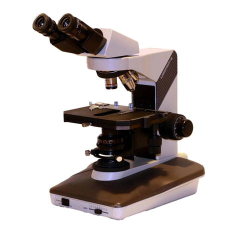
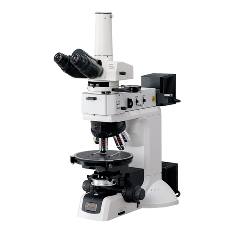
Nikon Eclipse E400 User manual

Instructions

Before
Using
pr
nnn
eno
con
-
i
ーーー
Thank
you
for
purchasing
this
Nikon
product.
This
instruction
manual
is
written
for the
users
of
Nikon
Microscope
ECLIPSE
E400.
To
ensure
correct
usage
read
this
manual
carefully
before
operating
the
instrument.
@
It
is
prohibited
to
reproduce
or
transmit
this
manual
in
part
or
whole
without Nikon's
expressed
permission.
©
The
contents
of
this
manual
are
subject
to
change
without
any
notice.
@
Although
every
effort
has
been
made
to
ensure
the
accuracy
of
this
manual,
if
you
note
any
points
that
are
unclear
or
incorrect,
contact
your
nearest
Nikon
representative.
—
—
Warning/Caution
Symbols
in
This
Manual
Though
Nikon
products
are
designed
to
provide
you
utmost
safety
during
use,
incorrect
usage
or
disregard
of
the
instructions
can
cause
personal
injury
or
property
damage.
For
your
safety,
read
the
instruction
manual
carefully
and
thoroughly
before
usage.
Do
not
discard
this
manual
but
keep
it
near
the
product
for
easy
reference.
Inside
this
instruction
manual,
safety
instructions
are
indicated
with
the
symbols
shown
below.
Be
sure
to
follow
the
instructions
marked
with
these
symbols
for
your
safety.
Symbol
Contents
Disregarding
instructions
marked
with
this
symbol
may
lead
to
death
or
WARNING
oo,
serious
injury.
Disregarding
instructions
marked
with
this
symbol
may
lead
to
injury
or
CAUTION
property
damage.
——
Symbol
on
the
product
Symbol
Contents
LN
Caution
for
heat
—

WARNING
ZE
Intended
product
use
This
microscope
should
only
be
used
for
microscopic
observation.
Do
not
use
it
for
any
other
purpose.
XE
L
Do
not
disassemble
Disassembly
may
cause
malfunction
and/or
electrical
shock.
Do
not
disassemble
any
parts
other
than
those
mentioned
in
this
manual.
If
you
notice
any
malfunction,
notify
your
nearest
Nikon
representative.
ο
Confirm
the
input
voltage
Make
sure
that
the
input
voltage
indicated
on
the
back
panel
of
the
microscope
is
the
same
as
your
regional
voltage.
If
not
the
same,
do
not
use
the
microscope;
instead,
notify
your
nearest
Nikon
representative.
If
the
microscope
is
used
with
the
wrong
input
voltage,
a
short
circuit
or
fire
may
result,
causing
the
damage
of
the
microscope.
Power
cord
To
prevent
electrical
shock,
always
turn
off
the
power
switch
(flip
it
to
the
©”
side)
before
connecting
or
disconnecting
the
power
cord.
Use
only
the
power
cord
provided
with
the
microscope.
(Refer
to
p.
24.)
Using
the
wrong
power
cord
could
result
in
damage
or
fire.
$,
eat
from
the
light
source
The
lamp
becomes
extremely
hot.
To
avoid
burns,
do
not
touch
the
lamp
and
the
area
around
it
while
the
lamp
is
lit
or
for
about
thirty
minutes
after
the
lamp
has
been
turned
off.
Furthermore,
in
order
to
avoid
the
risk
of
fire,
do
not
place
fabric,
paper
or
highly
flammable
materials
(such
as
gasoline,
petroleum
benzine,
paint
thinner
or
alcohol)
near
the
lamp
while
it
is
lit
or
for
about
thirty
minutes
after
it
has
been
turned
off.
The
back
of
the
microscope
also
becomes
hot
during
use.
Although
this
is
not
a
malfunction,
be
careful
not
to
touch
the
back
of
the
microscope
when
it
is
hot.

CAUTION
E
Installation
location
This
product
is
a
precision
optical
instrument.
Using
or
storing
the
instrument
under
unsuitable
conditions
may
damage
it
or
may
have
an
adverse
effect
on
its
precision.
The
following
conditions
should
be
kept
in
mind
when
selecting
the
installation
location.
©
Avoid
installing
in
a
place
exposed
to
direct
sunlight,
or
directly
under
room
lights
or
any
other
bright
place.
The
quality
of
the
view
through
the
microscope
deteriorates
in
bright
surroundings.
@
Install
in
a
place
with
little
dust
and
dirt.
©
Install
in
a
level
place
free
from
vibrations.
©
Install
on
a
sturdy
desk
or
table
that
is
able
to
bear
the
weight
of
the
microscope.
O
Do
not
install
in
a
warm
and
humid
location.
Otherwise,
condensation
or
mold
may
form
on
the
lenses,
degrading
performance
or
damaging
the
equipment.
Check
the
light
source
The
power
supply
contained
in
the
microscope
provides
the
power
for the
halogen
lamp
as
the
microscope
light
source.
Although
this
power
supply
can
power
a
halogen
lamp
of
up
to
6
V-30
W,
the
specified
lamp
must
be
used.
Use
of
a
non-specified
lamp
could
damage
the
microscope.
Specified
lamp:
6
V-30
W
(PHILIPS
5761)
Cautions
when
replacing
the
lamp
In
order
to
prevent
burns,
allow
the
lamp
to
cool
(for
at
least
thirty
minutes
after
turning
off
the
power)
before
replacing
the
lamp.
Furthermore,
to
prevent
electrical
shock
and
damage
to
the
microscope,
always
turn
off the
power
switch
(flip
it
to
the“
”
side)
and
unplug
the
power
cord
before
replacing
the
lamp.
After
replacing
the
lamp,
be
sure
to
attach
the
lamp
cover
securely.
Never
use
the
lamp
without
its
cover.
Cautions
when
operating
the
stage
The
stage
rack
protrudes
outward
when
the
stage
is
moved.
When
operating
the
focus
knobs
or
condenser
focus
knob,
be
careful
not
to
bump
your
hand
on
the
rack
since
the
end
of
the
rack
may
injure
your
hand.
n
em
ta
aray
mmm
oem
araras
rg
..
arm
ne
-en
P,

vi
-
CAUTION
¿
Я
Do
not
wet
Spilling
water
on
the
microscope
may
cause
electrical
short
circuits,
resulting
the
microscope
failure
or
abnormal
heat
generation.
If,
by
mistake,
water
or
liquid
is
spilled
on
the
microscope,
immediately
turn
off
the
power
switch
(flip
it
to
the
“ ”
side)
and
unplug
the
power
cord.
Then
use
a
dry
cloth
to
wipe
away
the
moisture.
If
any
liquid
gets
inside
of
the
microscope,
do
not
attempt
to
use
it;
instead,
contact
your
nearest
Nikon
representative.
x
Weak
electromagnetic
waves
This
microscope
emits
weak
electromagnetic
waves.
The
accuracy
of
any
precision
electronic
equipment
may
be
adversely
affected
if
positioned
near
this
microscope.
If
this
microscope
affects
TV
or
radio
reception,
move
the
radio
or
TV
away
from
the
microscope.
χει...
on
carrying
the
microscope
Securely
hold onto
the
microscope
with
the
base
of
the
arm
from
the
back
of
the
microscope.
Because
this
microscope
is
a
precision
optical
device,
handle
it
carefully
and
do
not
subject
it
to
strong
physical
shocks.
(The
precision
of
the
objective
in
particular
may
be
adversely
affected
by
even
weak
physical
shocks.)
In
addition,
do
not
grasp
the
focus
knobs,
the
eyepiece
tube,
the
stage,
etc.,
when
carrying
the
microscope;
there
is
a
chance
that
the
part
could
come
off,
and
the
microscope
could
be
damaged.
When
picking
up
the
microscope
or
putting
it
down,
be
careful
not
to
bump
the
lamp
cover
on
the
back
panel
against
other
things.
^7

Names
of
Component
Parts
and
Operational
Parts
Eyepiece
tube
Eyepiece
Diopter
adjustment
ring
Specimen
holder
Condenser
clamp
screw
Eyelevel
riser
Condenser
focus
knob
Revolving
nosepiece
Coarse
torque
/
tm
adjustment
ring
(TORQUE)
/
я
Objective
TORQUE)
|
イイ
1
1620
コ
0
бе
ER
AVE
|
Coarse
focus
knob
!
Fine
focus
knob
Brightness
adjuster
(LAMP)
Stage
rotation
clamp
screw
Auto-photo
switch
Auto-photo
voltage
ae
|
2488
selector
switch
г

Eyepiece
tube
clamp
screw
Eyelevel
riser
clamp
screw
n
\
Coarse
focus
stopper
1
ring
(CLAMP)
Fine
focus
knob
Condenser
aperture
diaphragm
ring
Condenser
Condenser
centering
screw
Power
switch
Y-axis
stage
motion
Field
diaphragm
ring
control
knob
X-axis
stage
motion
Field
lens
control
knob
Tool
holder
Rating
label
AC
input
connector
=
|
|
TS
HE
|
Lamp
cover
2
=
4
7
Power
cord
Back
panel

Proper
Use
Makes
a
Diffe
or
nan
ee
a
h
obtained
with
an
aperture
SHE
Έλις
αμ
ΕΠΟ:
ould
be
made
whenever
the
abp
tas
POS
Excessped
con
details
canin
be
süz
Proper
improper
adjustment
t

yt
&
Effects
of
Condenser
Focusing
and
Centering
Center
the
condenser
so
that
the
image
of
the
field
diaphragm
appears
clearly
in
the
center
of
the
view
field.
Hf
not
centered
he
field
diaphragm
will
be
shifted
out
of
position
and
resolution
will
be
reduced.
Always
make
P.27
correctly,
the
center
of
i
these
adjustments
when
assembling
the
microscope.
Off-center
SE
|
Out
of
focus
_
Extremely
out
of
focus
ob
_
Correct
adjustment
ーー
roll
|
ian
tt
ně
Image
of
the
field
-
Image
of
the
field
Extremely
poor
diaphragm
is
off-centered
Image
of
the
field
diaphragm diaphragm
appears
fuzzy
image
quality
appears
clearly
m
the
center
of
the
view
field
Effect
of
Color
Balancing
Filter
(NCB11)
if
specimens
are
observed
with
illumination
from
the
lamp
alone,
their
images
are
seen
with
a
yellow
tint.
Using
the
NCBI
filter
gives
the
images
a
natural
color
tone.
This
filter
is
normally
used
when
observing
specimens
by
bright
8
PAG
field
microscopy.
Without
using
the
NCB11
filter
r
Yellowish
color
tone
Using
the
NCB11
filter
Approximates
natural
daylight
color
Effect
of
Lamp
Voltage
Adjustment
ht
becomes
redder.
Conversely.
if
the
voltage
is
increased,
the
d
using
the
NCB11
filter
results
in
the
most
If
the
lamp
voltage
is
decreased,
the
color
tone
of
the
hig
color
tone
of
the
light
becomes
bluer.
Pressing
the
auto-photo
switch
an
natural
color
tone.
ms
P.18
Low
lamp
voltage
z
High
lamp
voltage
-photo
switch
on
nu
e
Reddish
color
tone
Auto-photo
Swite
Bluish
color
tone
Approximates
natural
daylight
color
——%

_Contents
e
e
eee
Before
Using
Names
of
Component
Parts
and
Operational
Parts
Proper
Use
Makes
a
Difference
Contents
Preparations
for
Microscopy
Placing
a
Specimen
on
the
Stage
Changing
Magnification
Photomicrography
Locking
the
Focus
Position
Changing
the
Torque
of
the
Coarse
Focus
Knob—
Changing
the
Torque
of
the
Stage
Motion
Control
Knobs
Selecting
a
Condenser
Assembling
and
Disassembling
the
Microscope
—
Replacing
the
Lamp
Installing
the
Condenser
Installing
the
Stage
Installing
the
Objectives
Installing
the
Eyelevel
Riser
(If
necessary)
一
一
一
Installing
the
Eyepiece
Tube
Installing
the
Eyepieces
Lens
Cleaning
Keeping
the
Microscope
Clean
Storage
Regular
Inspections
Troubleshooting
Tables
Specifications
and
Ratings
Index
1-4
10-11
13
14
15
16
17—18
19
20
21-22
23-25
26
27
28
28
29
30
30
30
31
31
32-34
35
36

|
Preparations
for
Microscopy
>
σα,
Q
Turn
on
the
power
switch.
(Flip
the
switch
to
the
”
"
side.)
As
soon
as
the
power
comes
on,
the
switch
lights.
O
Place
the
NCB11
filter
provided
on
the
field
lens
and
adjust
the
brightness
adjuster
to
a
suitable
brightness.
©
Diopter
and
Interpupillary
Distance
Adjustments
These
adjustments
are
performed
to
adjust
the
microscope
to
the
person
using
it.
Continued
use
of
the
microscope
without
properly
adjusting
diopter
and
interpupillary
distance
can
cause
eye
strain.
Make
sure
to
adjust
the
microscope
properly
whenever
you
use
it.
Diopter
adjustment
compensates
for
differences
in
vision
between
the
left
and
right
eyes.
In
addition
to
making
observation
through
both
eyes
easier,
this
adjustment
also
reduces
the
defocusing
when
changing
the
objective.
Perform
diopter
adjustment
for
both
eyepieces,
respectively.
3-1
=
Turn
the
diopter
adjustment
ring
on
the
eyepiece
to
align
the
edge
of
the
diopter
adjustment
ring
with
the
engraved
line.
(This
is
the
diopter
adjustment
"0"
position.)
.
.
The
diopter
adjustment
“O”
position
3-2
Turn
the
coarse
and
fine
focus
knobs
to
focus
on
the
specimen
with
the
40x
objective.
(When
it
is
difficult
to
focus
on
the
specimen,
first
focus
using
the
4x
or
10x
objective,
and
then
switch
to
the
40x
objective.) Since
the
distance
between
the
objective
tip
and
the
top
of
the
cover
glass
is
indicated
as
the
working
distance
(WD)
on
the
objective
barrel,
refer
to
that
distance
when
focusing
on
the
specimen.
3-3
Move
the
4x
or
10x
objective
into
the
optical
path.
Turn
the
diopter
adjustment
ring
on
the
eyepiece,
not
the
coarse
and
fine
focus
knobs,
to
focus
on
the
specimen.
Do
so
while
peering
through
the
right
eyepiece
with
your
right
eye
and
the
left
eyepiece
with
your
left
eye.
3-4
Adjust
the
spread
of
the
binocular
part
to
the
distance
between
your
eyes
so
that
the
field
of
view
for
each
eye
is
aligned
on
one
position
when
viewing
with
both
eyes.

FP
Placing
a
Specimen
on
the
Stage
$
O
Place
the
slide
glass
containing
the
specimen
on
the
stage
with
For one
slide
glass
the
cover
glass
facing
up
and
pinch
it
in
the
specimen
holder.
Adjust
the
i!lumination
brightness
with
the
brightness
adjuster.
Color
of
the
light
changes
at
the
same
time
brightness
changes.
If
brightness
is
reduced
by
lowering
the
voltage,
the
color
tone
of
the
light
from
the
lamp
becomes
redder.
If
the
voltage
is
increased,
the
color
tone
becomes
bluer.
In
order
to
maintain
a
constant
color
tone,
adjust
brightness
by
placing
ND
filter(s)
on
the
NCBI1
filter.

0
Adjustment
of
condenser
aperture
diaphragm
Adjust
the
diaphragm
according
to
the
objective
numerical
aperture.
Turning
the
condenser
aperture
diaphragm
ring
changes
the
size
of
the
aperture
diaphragm.
As
the
aperture
diaphragm
is
stopped
down,
brightness
reduces
and
the
details
of
the
specimen
become
more
difficult
to
see,
while
contrast
and
depth
of
focus
increase.
Conversely,
as
the
aperture
diaphragm
is
opened,
brightness
increases
and
the
details
become
easier
to
see,
while
contrast
and
depth
of
focus
reduce.
It
is
not
possible
to
adjust
one
pair
of
characteristics
without
affecting
the
other.
Generally,
a
well-defined
image
with
appropriate
contrast
can
be
obtained
with
an
aperture
setting
that
is
70%
to
80%
of
the
objective
numerical
aperture.
The
numerical
aperture
of
each
objective
is
indicated
on
the
barrel
of
the
objective.
An
indication
of
40x/0.75
means
that
the
magnification
is
40x
and
the
numerical
aperture
is
0.75.
If
the
aperture
diaphragm
is
stopped
down
too
far,
specimen
5
Magnification:
40x
Numerical
aperture:
0.75
details
will
become
difficult
to
see;
therefore,
except
when
contrast
is
extremely
low
such
as
when
viewing
a
nearly
transparent
specimen,
do
not
stop
down
the
aperture
to
less
than
60%
of
the
numerical
aperture
of
the
objective.
®@
Adjusting
the
size
of
the
aperture
diaphragm
according
to
the
condenser
scale
Because
the
condenser
scale
indicates
the
numerical
aperture,
adjust
the
aperture
diaphragm
ring
according
to
the
scale.
<Example>
Objective
with
N.A.
0.75
0.75
x
0.7
(to
0.8)
=
0.525
(to
0.6)
Adjust
À
to
this
value.
@
Adjusting
the
size
of
the
aperture
diaphragm
by
using
a
centering
telescope
(sold
separately)
Remove
one
of
the
eyepieces
and,
using
a
special
adapter
(sold
separately),
mount
a
centering
telescope
in
its
place.
Turn
the
aperture
diaphragm
ring
to
stop
down
the
aperture
diaphragm
as
far
as
possible.
While
holding
down
the
flange
of
the
centering
telescope,
turn
the
eyepiece
of
the
telescope
to
focus
on
the
aperture
diaphragm.
Turn
the
aperture
diaphragm
ring
to
adjust
the
size
of
the
aperture
diaphragm.
Remove
the
centering
telescope
and
the
adapter,
and
then
reinstall
the
eyepiece.
Adjustment
of
field
diaphragm
The
field
diaphragm
limits
illumination
to
the
area
of
the
specimen
being
viewed
to
prevent
excessive
light
from
entering
the
view
field.
Turning
the
field
diaphragm
ring
changes
the
size
of
the
field
diaphragm.
For
normal
observation,
the
size
of
the
diaphragm
should
be
just
outside
the
edge
of
the
view
field.
This
adjustment
can
produce
the
image
with
appropriate
contrast.

—
Photomicrography
@
Refer
to
the
instructions
of the
photomicrographic
equipment
being
used
for
detailed
information
on
the
assembly
method
and
photomicrographic
procedure.
O
Selecting
an
eyepiece
tube
:
A
trinocular
eyepiece
tube
equipped
with
a
vertical
tube
is
used.
There
are
two
types
of
trinocular
eyepiece
tubes.
Select
the
tube
according
to
the
purpose
of
use.
Operating
the
optical
path
selection
lever
changes
the
amount
of
light
entering
the
binocular
part
and
vertical
tube
of
the
eyepiece
tube
as
shown
below.
F
eyepiece
tube
T
eyepiece
tube
Light
proportion
Lever
Binocular
Vertical
Light
proportion
position
part
tube
Lever
Binocular
Vertical
me
position
part
tube
FAD
Bino---@Mioo
:
O
~
FF
RS
2
:
80
o
y
dg
2)
0
:
100
EMİ
poro;
3)0
:
100
EX
bo
ir;
m
BINO
PHOTO
1-1
Vertical
tube
adapter
A
photo
vertical
tube
adapter
is
provided
to
the
trinocular
eyepiece
tube
as
standard
equipment.
It
allows
a
photomicrographic
equipment
to
be
installed.
To
install
the
photo
vertical
tube
adapter,
insert
it
into
the
vertical
3
screws
tube
and
tighten
three
clamp
screws
on
the
vertical
tube
around
using
the
hexagonal
screwdriver
provided.
Replace
the
photo
tube
adapter
with
the
TV
vertical
tube
adapter
(sold
separately)
in
the
case
of
using
a
TV
camera.
1-2
Release
of
T
and
F
eyepiece
tubes
lever
clicking
“NO
CLICK”
switch
is
used
for
minimizing
slight
vibrations
produced
by
operation
of
the
optical
path
selection
lever.
This
switch
is
equipped
on
the
bottom
(installation)
surface
of
the
eyepiece
tube.
Turn
the
switch
in
the
arrow
direction
using
the
hexagonal
screwdriver
provided,
and
the
“NO
CLICK”
will
become
effective
to
remove
the
clicking
action
of
the
optical
path
selection
lever.

))
!-
VE”
©
Selecting
color
tone
and
brightness
The
color
tone
of
the
lamp
varies
according
to
the
voltage.
If
the
voltage
is
increased,
the
color
tone
of
the
lamp
becomes
bluer.
If
the
voltage
is
decreased,
the
color
tone
of
the
lamp
becomes
tedder.
Therefore,
in
order
to
obtain
the
best
color
reproduction
in
color
photomicrography,
the
lamp
voltage
should
be
kept
constant.
When
using
daylight-type
color
film,
the
standard
setup
is
to
use
the
color
balancing
filter
(NCB11)
and
set
the
Jamp
4)
The
auto-photo
switch
is
used
to
automatically
set
the
standard
lamp
voltage.
If
the
image
on
color
film
shot
with
the
auto-photo
voltage
to
the
standard
for
photomicrography.
switch
pushed
are
reddish
or
bluish,
finely
adjust
the
voltage
with
the
auto-photo
voltage
selector
switch.
The
center
position
of
the
5-level
slide
switch
is
the
standard
position.
Sliding
the
switch
forward
increases
the
bluish
tint
of
the
light,
while
sliding
the
switch
towards
the
back
increases
the
reddish
tint
of
the
light.
If
this
adjustment
is
not
enough
to
resolve
the
problem,
also
use
commercially
available
color
compensation
filters
(CC
filters).
©
Trimming
Loosen
the
stage
rotation
clamp
screw
in
order
to
rotate
the
stage.
Tighten
the
clamp
screw
at
the
desired
position
and
secure
in
position.

>)
-
Locking
the
Focus
Position
©
$
Coarse
focus
stopper
Once
the
coarse
focus
stopper
is
clamped
in
place,
the
coarse
focus
knob
cannot
be
used
to
move
the
stage
any
higher.
(Movement
of
the
stage
by
the
fine
focus
knob
is
not
restricted.)
In
effect,
once
the
coarse
focus
knob
is
clamped
in
place
at
the
focus
position,
a
rough
focus
can
be
attained
the
next
time
simply
by
turning
the
coarse
focus
knob
as
far
as
it
will
go.
This
feature
is
convenient
when
viewing
similar
specimens
one
after
another.
Using
the
coarse
focus
stopper
With
the
specimen
in
focus,
turn
the
coarse
focus
stopper
ring
as
far
as
it
will
go
(about
270°)
in
the
arrow
direction
indicated
on
the
microscope
base
(i.e.,
clockwise
direction).
The
coarse
focus
stopper
is
now
clamped
in
place.
When
changing
the
specimen,
tower
the
stage
by
turning
only
the
coarse
focus
knob.
After
changing
the
specimen,
gently
raise
the
stage
by
turning
only
the
coarse
focus
knob
as
far
as
it
will
go.
The
specimen
should
be
roughly
in
focus
when
the
stage
has
been
raised
as
far
as
it
will
go;
use
the fine
focus
knob
to
bring
the
specimen
into
perfect
focus.
If
the
coarse
focus
stopper
is
not
being
used,
be
sure
to
loosen
the
coarse
focus
stopper
ring
as
far
as
it
will
go
(by
turning
it
as
far
as
it
will
go
in
the
opposite
direction
of
the
arrow
indicated
on
the
microscope
base).
19

,
Changing
the
Torque
of
the
Coarse
Focus
Knob
The
torque
of
the
coarse
focus
knob
can
be
adjusted.
To
increase
the
torque,
turn
the
coarse torque
adjustment
ring
(TORQUE)
located
behind
the
coarse
focus
knob
in
the
arrow
direction
indicated
on
the
microscope
base
(i.e.,
the
counter-clockwise
direction).
To
reduce
the
torque,
turn
the
ring
in
the
opposite
direction
of the
arrow
(i.e.,
clockwise
direction).
Increase
the
torque
Never
attempt
either
of
the
following
actions.
These
actions
will
damage
the
microscope.
@
Rotating
the
left
and
right
knobs
in
opposite
directions
at
the
same
time.
€
Continuing
to
rotate
the
coarse
focus
knob
after
the
stage
has
reached
the
limit
of
its
motion.
,
Changing
the
Torque
of
The
torque
of
the
X-axis
and
Y-axis
stage
motion
control
knobs
can
each
be
adjusted.
the
Stage
Motion
Control
Knobs
m
veš
ο
Adjustment
of
torque
of
Y-axis
stage
motion
To
tighten
the
tension
in
the
Y-axis,
turn
Knob
B
in
the
direction
of
arrow
“a”
while
holding
Knob
A;
to
reduce
the
tension,
turn
Knob
B
in
the
opposite
direction.
©
Adjustment
of
torque
of
X-axis
stage
-
motion
To
tighten
the
tension
in
the
X-axis,
turn
Knob
C
in
the
direction
of
arrow
“b”
while
holding
Knob
D;
to
reduce
the
tension,
turn
Knob
C
in
the
opposite
direction.

ì
Ma
-
Selecting
a
Condenser
Object!
Achromat/
Swi
Low-
bjective
aplanat
wing-out
Achromat
Abbe
magnification
magnification
condenser
condenser
condenser
condenser
condenser
1x
κ
κ
x x
2x
x
x x
©
(Note
2)
(Note
3)
4x
x
(Note
1)
(Note
1)
10x
to
100x
©
x
©
:
Optimum
:
Appropriate
X:
Inappropriate
Note
1:
The
entire
field
of
view
may
not
be
covered
when
a
UW
eyepiece
is
used.
Note
2:
Indoor
lighting
and
similar
light
sources
may
be
reflected
off
the
surface
of
the
condenser
lens
and
be
visible
within
the
field
of
view.
When
this
happens,
either
dim
the
indoor
lighting
or
prevent
strong
outside
light
from
entering
onto
the
stage.
Note
3:
Swing
out
the
top
lens.
@
Depending
on
the
type
of
objective,
the
whole
numerical
aperture
of
the
objective
may
not
be
covered.
For
example,
when
an
objective
with
N.A.
1.4
is
used
in
combination
with
a
swing-out
condenser
or
abbe
condenser,
the
aperture
size
will
only
be
about
65%
of
the
objective's
N.A.
even
when
it
is
opened
to
its
limit.
O
For
the
universal
system
condenser
and
phase
contrast
condensers,
refer
to
each
instruction
manual.
ο
Oil-immersion
operation
(using
an
oil-immersion
type
objective
and
condenser)
Objectives
marked
“Oil”
are
oil-immersion
type
objectives.
These
objectives
are
used
with
the
provided
immersion
oil
applied
between
the
specimen
and
the
tip
of
the
objective.
In
order
to
get
maximum
performance
from
oil-immersion
type
objectives
with
a
numerical
aperture
of
1.0
or
greater,
an
oil-
immersion
type
achromatic
aplanat
condenser
must
also
be
used.
Oil-immersion
type
condensers
are
used
with
oil
applied
between
the
specimen
and
the
condenser
lens.
Bubbles
in
the
oil
will
adversely
affect
the
viewing
of
the
image.
Be
careful
to
prevent
the
formation
of
air
bubbles.
To
check
for
air
bubbles,
remove
the
eyepieces,
open
the
field
diaphragm
and
the
aperture
diaphragm
as
far
as
possible,
and
look
at
the
exit
pupil
of
the
objective
within
the
eyepiece
tube.
(The
exit
pupil
will
appear
as
a
bright
circle.)
If
it
is
difficult
to
see
if
there
are
any
bubbles,
mount
a
centering
telescope
(sold
separately)
on
an
eyepiece
sleeve
by
using
an
adapter
(sold
separately).
Then,
while
turning
the
eyepiece
on
the
centering
telescope
to
change
the
focus,
look
through
the
centering telescope
for
air
bubbles.
If
there
are
bubbles
in
the
oil,
remove
them
by
one
of
the
following
methods:
Turn
the
revolving
nosepiece
slightly
to
move
the
oil-immersed
objective
back
and
forth
one
or
two
times.
(In
the
case
of
the
condenser,
gently
turn
the
condenser
focus
knob
to
move
the
condenser
up
and
down
slightly.)
©
Add
more
oil.
<>
Remove
the
oil
and
replace
it
with
new
oil.
A
©

© Use
as
little
oil
as
possible
(just
enough
to
fill
the
space
between
the
tip
of
the
objective
and
the
specimen,
or
between
the
tip
of
the
condenser
and
the
specimen).
If
too
much
oil
is
applied,
the
excess
will
flow
onto
the
stage
and
around
the
condenser.
©
Any
oil
remaining
on
oil-immersion
type
objectives
or
on
the
tip
of
dry-type
objectives
has
a
negative
effect
on
viewing.
After using
oil,
wipe
all
of
it
away
and
make
sure
that
there
is
no
oil
on
the
tips
of
the
other
objectives.
The
oil
on
the
condenser
lens
should
also
be
carefully
wiped
away
after
use.
@
Use
petroleum
benzine
to
wipe
away
immersion
oil.
Finish
the
cleanup
by
wiping
with
absolute
alcohol
(ethyl
alcohol
or
methyl
alcohol).
©
If
you
cannot
obtain
petroleum
benzine,
use
methyl!
alcohol.
But
it
will
be
necessary
to
wipe
the
surfaces
repeatedly
(usually,
three
or
four
times)
to
clean
the
lenses.
WARNING
@
When
using
petroleum
benzine
or
absolute
alcohol,
please
follow
the
instructions
provided
by
the
manufacturer.
Keep
these
flammable
liquids
away
from
fire
or
sparks.
—
Precautions
when
using
immersion
oil
@
Make
sure
to
securely
tighten
the
cap
after
use.
After
adding
oil to
the
container,
securely
tighten
the
base
cap.
Since
the
base
cap
may
become
loose
by
itself
after
having
been
used
for
a
long
time,
periodically
check
to
make
sure
it
is
tight.
Oil
may
leak
out
if
the
cap
is
loose.
@
Do
not
press
on
the
container
with
excessive
force.
This
may
cause
the
oil
suddenly
spray
from
the
container.
©
Wipe
off
any
oil
that
collects
on
the
outside
of
the
container
during
the
course
of
use.
O
Be
careful
so
that
oil
does
not
get
in
your
eyes.
Although
the
oil
is
not
toxic,
apply
the
first-aid
measures
listed
below
if
it
should
come
in
contact
with
the
skin
or
enter
the
eyes.
©
Contact
with
skin:
Completely
wash
off
with
soap
and
water.
©
Enters
the
eyes:
Rinse
thoroughly
with
pure
water
(for
at
least
15
minutes)
and
seek
medical
attention.
O
Do
not
place
immersion
oil
in
a
location
exposed
to
outside
light
(or
UV
light).
©
Water-immersion
operation
-
(using
a
water-immersion
type
objective
and
condenser)
O
Objectives
marked
“WI”
or
“W”
are
water-immersion
type
objectives.
These
objectives
are
used
with
the
immersion
water
(distilled
water
or
physiological
saline)
applied
between
the
specimen
and
objective.
Microscopy
is
performed
in
the
same
manner
as
for
an
oil-immersion
type
objective.
@
Since
water
evaporates
easily,
periodically
check
it
during
observation.
Applying
excess
water
will
cause
it
to
flow
onto
the
stage
and
condenser
resulting
in
corrosion.
@
After
use,
wipe
any
water
from
the
tip
of
the
objective
and
finish
the
cleanup
process
by
wiping
with
absolute
alcohol.
@
When
the
water
dries
and
leaves
a
stain,
apply
a
small
amount
of
neutral
detergent
and
wipe
gently
to
remove
the stain.
Finish
the
cleanup
process
by
wiping
with
absolute
alcohol.

Assembling
and
Disassembling
1
+
27
the
Microscope
ei
WARNING
©
In
order
to
prevent
electrical
shock
and
fire,
turn
off
the
power
switch
(flip
to
the
“ ”
side)
during
assembly.
CAUTION
>
>
@
Attach
the
eyepiece
tube
first
for
assembling
the
microscope.
@
When
moving
the
microscope,
securely
grasp
the
arm from
the
back
of
the
microscope
with both
hands.
@
Do
not
grasp
the
coarse
focus
knob,
the fine
focus
knob,
eyepiece
tube
or
stage,
etc.,
when
carrying
the
microscope;
there
is
a
chance
that
the
part
could
come
off,
and
the
microscope
could
be
damaged.
@
Be
careful
not
to
bump
the
lamp
cover
on
the
back
of
the
microscope
when
picking
it
up
or
putting
it
down.
Ф
Be
careful
not
to
pinch
your
hands
or
fingers
when
setting
up
the
microscope.
@
Do
not
touch
the
lens
surface
with
bare
hands.
Fingerprints
or
dirt
on
the
lens
will
adversely
affect
the
viewing
of
the
image.
@
This
microscope
is a
precision
optical
device.
Handle
it
carefully
and
do
not
subject
it
to
strong
physical
shocks.
(The
precision
of
the
objectives
in
particular
may
be
adversely
affected
by
even
weak
physical
shocks.)
ο
Tools
needed
@
Hexagonal
screwdriver
(1
provided)
When
not
using,
insert
it
in
the
tool
holder
on
the
back
of
the
microscope.
の
Confirm
the
input
voltage
全
Hikon
V
MODEL
EDLIESE
£400
420v
e
o
50/60Hz
MADE
IN
JAPAN
(EDA)
(AN
ARNING
@
Make
sure
that the
input
voltage
indicated
on
the
back
panel
of
the
microscope
is
the
same
as
your
regional
voltage.
@
If
the
indicated
voltage
is
different,
do
not
use
the
microscope;
instead,
contact
your
nearest
Nikon
representative.
©
If
a
microscope
is
used
with
the
wrong
input
voltage,
a
short
circuit
or
fire
may
result,
and
the
microscope
may
be
damaged.
Other manuals for Eclipse E400
1
Table of contents
Other Nikon Microscope manuals

Nikon
Nikon Elcipse TE2000 User manual

Nikon
Nikon SMZ1500 User manual

Nikon
Nikon Optiphot User manual

Nikon
Nikon SMZ-1 User manual

Nikon
Nikon 50i User manual
Nikon
Nikon LABOPHOT-2 User manual

Nikon
Nikon Ti-E User manual

Nikon
Nikon eclipse Ci-S User manual

Nikon
Nikon Eclipse 800 User manual

Nikon
Nikon eclipse lv150 User manual

Nikon
Nikon SMZ-1B User manual

Nikon
Nikon SMZ745T User manual

Nikon
Nikon E800 User manual

Nikon
Nikon ECLIPSE Ni-E User manual

Nikon
Nikon SMZ-U Manual

Nikon
Nikon Epiphot 300 User manual

Nikon
Nikon ECLIPSE Ti2-U User manual

Nikon
Nikon Eclipse Ti-E User manual
Nikon
Nikon Eclipse L200A User manual

Nikon
Nikon Alphapot2 Manual