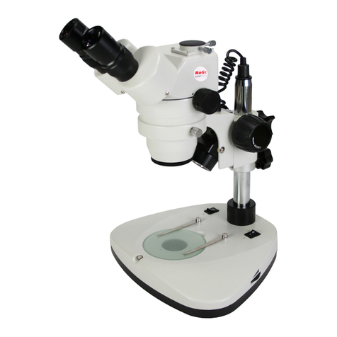
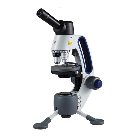
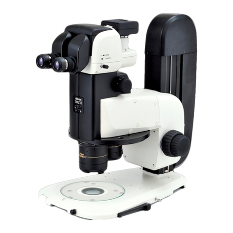
Swift SM100 Series User manual

Swift SM100 Series
Stereo Microscope
Use and Care Manual
SWIFT OPTICAL Enduring Quality and Technical Excellence

2

3
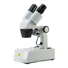
SWIFT SM100 SERIES STEREO MICROSCOPE
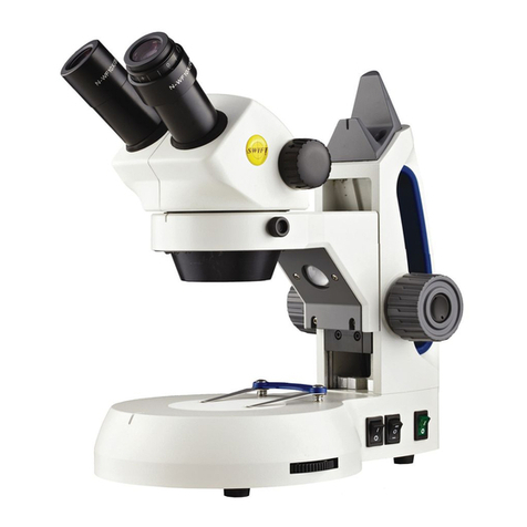
The Swift SM100 Series stereo microscope is a full size, well-
balanced, stereoscopic instrument producing an erect, three-
dimensional image with a large, comfortable field of view.
The SM100 Series incorporates features to enhance and provide
maximum versatility for classroom and professional use. It is built to
rigid optical and mechanical standards; the result of continuing
progress from Swift to provide a durable, modern instrument that
meets today’s stringent requirements.

4
SM100 CORDED SERIES STEREO MICROSCOPE
SPECIFICATIONS
Model Number SM101 SM102 SM105
Objectives
1X, 3X 2X, 4X 1X – 3X ZOOM
Eyepieces
N-WF10X/20 N-WF10X/20 N-WF10X/20
Total
Magnification/
Field of View
10X / 20mm
30X / 6.5mm 10X / 10mm
40X / 5mm
10X / 20mm
20X / 10mm
30X / 6.5mm
Working
Distance 77mm 77mm 77mm
Max Specimen
Height 36mm 36mm 36mm
SM100
Illuminator
(incident &
transmitted)
Turret variable
6 x .06W LED,
Top variable
.5W, Bottom
.5W LED.
Corded Stand
Turret variable
6 x .06W LED,
Top variable
.5W, Bottom
.5W LED.
Corded Stand
Turret variable
6 x .06W LED,
Top variable
.5W, Bottom
.5W LED.
Corded Stand
SM100 CORDLESS SERIES STEREO MICROSCOPE
SPECIFICATIONS
Model Number SM101-C SM102-C SM105-C
Objectives
1X, 3X 2X, 4X 1X – 3X ZOOM
Eyepieces
N-WF10X/20 N-WF10X/20 N-WF10X/20
Total
Magnification/
Field of View 10X / 20mm
30X / 6.5mm 10X / 10mm
40X / 5mm
10X / 20mm
20X / 10mm
30X / 6.5mm
Working
Distance 77mm 77mm 77mm
Max Specimen
Height 36mm 36mm 36mm
SM100
Illuminator
(incident &
transmitted)
Turret variable
6 x .06W LED,
Top variable
.5W, Bottom
.5W LED.
Corded Stand
Turret variable
6 x .06W LED,
Top variable
.5W, Bottom
.5W LED.
Corded Stand
Turret variable
6 x .06W LED,
Top variable
.5W, Bottom
.5W LED.
Corded Stand

5
Head
Focusing
Control Knob
Turret
Stage Clips
Stage Plate
(SM105-C Pictured)
Diopter
Adjustment
Bottom
Illuminator
Top Turret &
Angled
Illuminators
Illuminator Dimmer
Control
Illuminator On/Off
Switches
Eyepiece
Eyepiece tube
Diopter Adjustment
Power
Switch
Stand
Cord Holder
Magnification
Knob
USB Port

6
COMPONENTS OF THE STEREO MICROSCOPE
BOTTOM ILLUMINATOR – This is the light source mounted in the
base to provide trans-illumination.
DIOPTER ADJUSTMENT – Located on the left eyepiece tube of the
SM100 Series. This adjustment is used to fine focus the optics to
compensate for visual differences between the user’s eyes.
EYEPIECE – The upper optical element that further magnifies the
primary image of the specimen and brings the light rays in focus at
the eyepoint.
EYEPIECE TUBE – This is the part of the head that holds the
eyepieces in place. Set screws in the eyepiece tubes can be used to
lock the eyepieces in place.
STAGE CLIP – Used to hold specimen in place.
FOCUSING CONTROL KNOB – The focusing control knobs located on
either side of the stand are used to raise or lower the head to bring
the specimen into focus. The control knobs incorporate a slip
clutch system which prevents the head from traveling past both
ends of the focusing range. When the focusing limit is reached, the
clutch system begins to slip to prevent gear damage.
HEAD – The 360˚ rotatable component that contains all of the
optical elements of the stereo microscope including the eyepieces,
refracting mirrors and objective lenses. The head of the SM100
series is designed to allow users to adjust the interpupillary
distance of the eyepieces for proper viewing.
ILLUMINATOR DIMMER CONTROL – The intensity of the top
(incident light) LEDs or bottom (trans-illumination) LED can be
adjusted to the preferred brightness (0 through 10) by using the
dimmer control located on the side of the base.
ILLUMINATOR ON/OFF SWITCHES – A tri-illumination system is
incorporated into the stand. The illumination system is controlled
by top (incident light) and bottom (trans-illumination) on/off
switches located at the base of the stand. The incident illuminator
is used for opaque specimens, while the trans-illuminator
effectively illuminates the internal structure of transparent
specimens. Translucent specimens may be seen in greater detail if
both illuminators are used simultaneously.

7
MAGNIFICATION KNOB – Used to change the SM100 series
magnification settings.
STAGE PLATE – Frosted glass, black and white stage plates are
provided with the microscope stand. The frosted glass stage plate
allows light from the bottom illuminator to pass through. The black
and white stage plates can be used for additional contrast to the
specimen that is being viewed.
STAND – Used to support the stereo microscope head. The height is
adjustable which allows the head to change its focusing range. The
stand also contains the top and bottom Illuminators.
TOP ANGLED ILLUMINATOR – The top .5W LED light source is fixed
at a 45˚ angle.
TOP TURRET ILLUMINATOR – The top 6 x .06W LED light source is
fixed in a downward in a vertical position to provide maximum
illumination of the specimen.
TURRET – The round barrel that houses the objective lenses. The
SM100 Series has magnifications that can be changed by rotating the
black turret magnification knob to a different set of objective
lenses.
USB Port – This port supplies 5VDC 500Ma for optional accessories.
This port can be used to charge MP3 device or add-on USB lighting.
OPERATING YOUR SM100 SERIES STEREO MICROSCOPE
1. Place the specimen onto the stage plate and select the type of
illumination. If the specimen is transparent, turn on the bottom
illumination. If the specimen is opaque, turn on the top
illuminator.
2. The magnification knob is located on the right hand side of the
microscope head. The knob is clearly marked with the optical
magnification setting. To change magnifications, rotate the
black magnification knob in one direction or in the opposite, as
far as it will turn. This will place one pair of objectives in
alignment for viewing. The power that is in use is marked on
the black magnification knob. Please start with the highest
objective setting.
3. Look through the eyepieces and rotate the focus control knob to
focus the specimen in the field of view.

8
4. Grasp the eyepiece tubes and move them either closer together
or farther apart, to change the interpupillary distance to obtain
a clear image. Note, if two separate images are observed, the
eyepiece tubes are too far apart and should be moved together.
If two overlapping images are seen, the eyepiece tubes are too
close together and should be moved apart.
5. Close your left eye and adjust the focus controls so the image is
in sharp focus, while viewing with the right eye only.
6. Close your right eye and while viewing with the left eye
only, adjust the diopter ring on the left eyetube to bring the
image of the specimen into sharp focus. The optical system is
now adjusted to your particular vision.
7. Rotate the black magnification knob to lowest magnification.
Only minor refocusing using the focusing control knob should be
required. Your microscope is now parfocalled.
SERVICE AND CLEANING
Use and store your instrument in a dry environment. When not
being used, microscopes should be stored with dust covers in place
and illuminators turned off. Avoid direct sunlight, high
temperatures, moisture, smoke, and fungus. Your Swift stereo
microscope is designed to function satisfactorily with only ordinary
maintenance. The instrument should be periodically serviced by a
qualified, authorized service technician, who will clean, re-
lubricate and perform routine adjustments. Eyepieces should be
cleaned as often as necessary to allow unobstructed viewing. Clean
the eyepieces by brushing away dust particles using a soft camel
hair brush or with air pressure, then moistening the lens by
breathing onto it. Wipe the lens carefully with quality lens tissue. If
dirt or other foreign matter still remains, it may be necessary to use
water or optical cleaner (eyeglass or camera lens). Note: the lens
tissue should be moistened, not saturated, for cleaning, after which
the lens should be dried using a quality lens tissue. Painted surfaces
should be cleaned with soapy water or mild non-abrasive cleaners
and a soft cloth. Do not use solvents on painted surfaces.
Unauthorized personnel should never disassemble lens assemblies or
other precision components. For information regarding service,
contact your local authorized Swift dealer or Swift customer service
at (877) 967-9438.

9
BULB REPLACEMENT
Unplug the stereo microscope from the electrical outlet and
remove specimens from the stage before you attempt to replace
an LED.
To prolong the life of the LED, you should always turn off the unit
when not in use.
The extra long life LED incidental (top) illuminator bulbs (Swift
MA14780 & MA14781) can be replaced by removing the five retaining
screws holding on the Illumination plate (See Fig 1.). This will
require the use of a short handle screw driver. They can then be
unclipped and replaced (See Fig 2.).
The transmitted (bottom) illumination bulb is Swift MA14782 3.5V
150mA LED Bulb. The bottom bulb may be replaced by carefully
laying your stereoscope on its side and using a Phillips screw driver
remove the four screws securing the rubber feet and base plate to
illuminator base. Remove four 3mm Phillips head screws securing
lamp housing to lamp bracket (See Fig 3.); then remove lamp
housing. Carefully unplug LED lamp connector. Replace LED lamp
assembly and then, reverse the above process.
Fig 1. Fig 2.
Fig 3.

10
TENSION CONTROL OF FOCUSING MOVEMENT
The focus tension is easily adjusted by using the Swift adjustment
wrench. This wrench fits the tension collar found on the focusing
controls, between the knob and upright support. A clockwise turn
of this collar moves it toward the upright support and increases
tension, while a counter clockwise turn moves the collar toward the
knob and decreases tension (see illustration).
COMMON PROBLEMS IN MICROSCOPY
If you have a problem, you may be able to correct it yourself. Here
are a few common problems and easy solutions you may want to try
before calling for service.
CAUTION – Never disassemble mechanical or optical components.
This servicing should only be done by an authorized Swift technician.
The Limited Lifetime Warranty will be null and void if the
mechanical or optical components are disassembled by a non-Swift
dealer.
A. PROBLEM – The illuminator light does not come on
CORRECTION –
1. Make sure the microscope is plugged into a functional
electrical socket.
2. Make sure the bottom illuminator dimmer control is set above
“0”
3. The bulb may need to be replaced. See “Bulb replacement”
on page 8.

11
B. PROBLEM – Unable to bring specimen into focus.
CORRECTION –
1. Eye lens of the eyepiece is partially unscrewed. Remove the
eyepiece and screw the two sections together.
2. The black turret knob may need to be fully rotated to align
the objective lenses into the correct position.
3. The specimen may not be centered properly on the stage and
needs to be re-positioned to be in the optical path.
C. PROBLEM – Image of the specimen goes out of the focus all by
itself.
CORRECTION - Use the tension control collar to tighten the
focusing mechanism found on the focusing spindle.
D. PROBLEM – Focusing knobs turn with difficulty even with tension-
collar loosened.
CORRECTION – Microscope should be disassembled, cleaned and
re-lubricated by a qualified, authorized technician.
PARTS and ACCESSORIES
MA10589 N-WF10X/20 (single)
MA10590 N-WF10X/20 adjustable Diopter (single)
MA14780 3.5V 150mA LED Bulb (Top illuminator)
MA14781 3.5V 150mA LED Bulb (Arm illuminator)
MA14782 3.5V 150mA LED Bulb (Bottom illuminator)
MA14281 Power supply converter (100-240VAC in, 4.5VDC 1a out)
MA19029 Rubber Eyeshields, pair
MA2620B Black Stage Plate
MA2620W White Stage Plate
MA2621 Frosted Stage Plate
MA533 Dustcover
SWIFT OPTICAL INSTRUMENTS, INC. LIMITED LIFETIME WARRANTY
Please see our website, www.swiftoptical.com, for complete
warranty details and exclusions.

12
Swift Optical Instruments, Inc.● (877) 967-9438 ●
www.swiftoptical.com
Other manuals for SM100 Series
1
Table of contents
Other Swift Microscope manuals

Swift
Swift M2000DF Series Installation instructions

Swift
Swift SW200DL User manual

Swift
Swift M970 series User manual

Swift
Swift SM90 Installation instructions

Swift
Swift M10L Series User manual

Swift
Swift SW50 User manual

Swift
Swift M3-M User manual

Swift
Swift M3200 series User manual

Swift
Swift M2252DGL Series User manual

Swift
Swift SW150 User manual

Swift
Swift SW380 Series User manual

Swift
Swift M10DB-MP User manual

Swift
Swift SM100 Series User manual

Swift
Swift SM91 User manual

Swift
Swift STELLAR 1 Series User manual

Swift
Swift Stereo SM80 Installation instructions

Swift
Swift SW100 User manual

Swift
Swift SW200 User manual

Swift
Swift M3 User manual

Swift
Swift SW350B User manual