manuals.online logo
Brands
  1. Home
  2. •
  3. Brands
  4. •
  5. Der Holzwurm
  6. •
  7. Outdoor Storage
  8. •
  9. Der Holzwurm 3580023 User manual

Der Holzwurm 3580023 User manual

4’ x 6’ Garden Shed
Assembly Guide
2
3
[D1] x 1
1416mm
[D2] x 2
275mm
[D3] x 2
1061 mm
[D4] x 1
1416 mm
[Q1] x 3
1540 mm
[Q2] x 4
1540 mm
[Q3] x 4
1540 mm
[B1] x 1
839 mm
[B2] x 1
839 mm
[B3] x 1
839 mm
[B4] x 1
839 mm
[B5] x 1
1041 mm
[B6] x 1
1041mm [SL] x 1 [SR] x 1
[FL] x 1 [FR] x 1 [W1] x 3
1216 mm
[W2] x 1
1216 mm
[L1] x 2
1223 mm
[L2] x 2
1011mm
[L3] x 2
887 mm
[J3] x 2
60 mm [DL1] x 4 [DL2] x 2
[BL1] x 4 [BL2] x 2 [L4] x 4
136 mm [G5] x 4
[DL] x 1
[DR] x 1 [LL] x 1 [LR] x 1
PART LIST
4
[Latch] x 1 [spring latch] x 2 [S1] x 35
[S2] x 35 [S3] x 210 [S4] x 210
PART LIST
[S5] x 30 [S6] x 4 [S7] x 6 [S8] x 4
WERKZEUGE
M6
M4
5
WARNING
Keep this guide for future reference. Read carefully.
Safety
Make sure you have access to all sides of the shed during construction.
Ensure that all parts are present before starting assembly.
Remove all parts from the box and sort them by number. Ensure that you have all elements required to
build your garden shed.
Always wear work gloves, long sleeves and safety goggles during assembly of the garden shed. Some
components contain sharp edges and may cause damage.
Keep children and animals away from the assembly site.
When necessary to use a ladder, ensure ground stability is adequate. Never rest your entire weight on
the roof or on any other part of the garden shed.
Do not attempt to assemble the garden shed in strong windy conditions due to the risk of making site
conditions difficult and dangerous.
To maintain their original condition, ensure that nothing is placed on top of shed components.
Do not store pool chemicals in your garden shed.
Combustible and corrosive materials must be stored in watertight containers.
Set your drill’s torque limit to prevent damage to the metal parts.
Remove snow from the roof after each snowfall. A thickness of over 10 cm of snow is hazardous.
Do not walk on the roof.
Weather
DO NOT attempt to assemble your shed in windy weather.
Misc.
At least two adults are needed to finish the assembly.
Average assembly time is 8 man-hours.
6
2
LEGEND
: marks a step.
IMPORTANT: EXECUTE THESE STEPS IN NUMERICAL ORDER.
: marks a sub-step and the alphabetical order of executing these sub-steps.
IMPORTANT: EXECUTE THESE STEPS IN ALPHABETICAL ORDER.
: marks the orientation of the shed.
: marks a part.
: marks a screw hole and the sequential order of fixing screws and panels. IMPORTANT: FIX SCREWS IN NU-
MERICAL ORDER.
: marks the sequential order of fixing screws on a panel. IMPORTANT: FIX SCREWS IN NUMERICAL ORDER.
: marks locations.
: marks a screw hole that SHOULD NOT be fixed.
: marks an unacceptable layout.
: marks an acceptable layout.
[DL1]
A
Front (Door)
①
S-1
Concrete Slab
7
GENERAL RULES
Wall panels and roof panels
Remove the protective films prior to assembly.
▲Wall Panels: as seen from the outside.
Exterior Top
▲Roof Panels: as seen from the top.
▲Roof Panels: Pay special attention to the very left and the very right panels. Lay the panels out in
such a way that the flat edges of the panels, not the U channels, extend outward.
Left Edge Right Edge
▲Roof Panels: For Roof panels that are caught in between, lay them out in such a way that the flat
edges of the panels do not stack. U channels stacking with U channels and U channels stacking with
flat edges are acceptable.
Detailed layout plans are illustrated in this manual.
8
Aluminium Frames
Two sets of Aluminium frames are used in this shed, namely, [D1] to [D4] and [B1] to [B6]. We will name
[D1] to [D5] as outer base frames, and [B1] to [B6] as top frames.
GENERAL RULES
Screws
[S1]
[S2] [S3] [S4] [S5]
1. Always use [S1] and [S2] in pairs.
2. Use [S4] with [S3] and [S1] to protect panels. [S4] is not used in certain steps.
3. Use [S5] with [S3] when assembling roof panels.
4. Due to space restraints, [S3] and [S4] will not be additionally marked.
5. When the assembly is finished, see to it that visible [S3]s are covered by [S5].
6. When the assembly is finished, see to it that all visible screw holes are fixed.
Screw holes on Aluminium Frames
Take a look at all these Aluminium frames and you will see screw holes drilled on these frames. We will
name screw holes on Aluminium frames as pinpoint holes, and screw holes on panels as screw holes.
Pinpoint Holes
Screw Holes
9
GENERAL RULES
Screw holes on Aluminium Frames continued
This manual is organized in such a way that you have to assemble the wall panels from the outer base
frames to the top frames. This is because outer base frames have all the needed pinpoint holes, but the
top frames only have two pinpoint holes, one on each end, except for [B1] which has three holes.
When fixing screw holes, see to it that,
1. When fixing screw holes on the outer base frames, namely, assembling wall frames to the outer base
frame, make sure the screw holes on the wall panel stack precisely with pinpoint holes on the frames.
This needs to be stressed because Aluminium frames are sturdy but soft, meaning you can drill through
the frames even though you stack the panels incorrectly.
Screw hole and pinpoint
2. When fixing screw holes on the top frames, make sure the very left and right screw holes on panels
stack precisely with the pinpoint holes on the top frames.
10
1
The site must be prepared so that the base of the shed is level all round and checking with a spirit level
is required.
This shed must be secured onto a firm and leveled foundation, preferably concrete slabs.
The foundation must have a minimum thickness of 10 cm. Allow cement to dry for at least 48 hours.
The foundation can also be constructed from bricks or blocks.
The manufacturer is not liable for the choice and quality of the foundation.
FOUNDATION AND OUTER BASE
1.1
11
[D1] x 1
1416mm
[D2] x 2
275mm
1.2
1
1.3
Concrete Slab
[S3] x 12
A
A
A
A
A
[S3]
[S3]
[D3]
[D1]
[DL1]
[D3]
[D3]
[D1]
[D1]
A
A
[S6]
8cm Deep
[S6] x 4
FOUNDATION AND OUTER BASE
A
A
A
[DL1] x 4
[DL2] x 2
[D2]
[D2]
B
[S3] [S3]
[D2] [D1]
[DL2]
B
B
[D3] x 2
1061 mm
12
[Q2] x 4
1540 mm
[S4] x 12
2
[Q2]
A
Front (Door)
2.1
[S3] x 12
There are five screw holes
at the bottom end of [Q2].
Only fix the three holes in
the middle.
DO NOT FIX THE TWO
SCREW HOLES MARKED.
WALL PANELS
A
[Q2]
[Q2]
[Q2]
Repeat Step 2.1 to finish the assembly of the rest 3 x [Q2].
[J3]
13
[B1] x 1 839 mm
[B2] x 1 839 mm
[BL1] x 4
2
2.2
[B3] x 1 839 mm
[B4] x 1 839 mm
WALL PANELS
2.3
[BL2] x 2
[S3] x 8
[B1]
[B2]
A
B
C
A
[B1]
[BL2]
[B2]
B
[B1]
[BL1]
C
[B2]
[BL1]
A
[BL2]
[B4]
[B3]
DO NOT REMOVE STICKERS ON [B1] to [B6] BEFORE FINISHING STEP 2.7
[S3] [S3]
[S3]
[S3]
B
[B3]
[B4]
A
C
B
B
[BL1]
[B3]
C
[B4]
[BL1]
14
2WALL PANELS
STEP 2.4 and 2.5 need special attentions, because [B1+B2] and [B3+B4] look awfully similar. Before
heading to STEP 2.6, make sure:
1. The head of the screws on [B1+B2] and [B3+B4] face downward, as is shown below.
2. Keep this orientation of [B1+B2] and [B3+B4] when executing Step 2.4. If you do it correctly, you will
find that the narrow U-channels on [B1+B2] and [B3+B4] face outwards, namely, face towards the wall
panels.
And another narrow U-channel faces upward.
3. If, for whatever reason, the flat surface of [B1+B2] or [B3+B4] faces upward, you are doing it wrong.
Narrow U-channel faces outward.
Narrow U-channel faces upward
Wide U-channel faces inward.
Narrow U-channel faces upward
15
2
2.4
[S3] x 6
[S4] x 6
Assembled [B1+B2]
x 1
A
A
B
B
[B2]
[B1]
▲Only fix three screws in each step. Pay special attention to the ori-
entation of [B1+B2]. Refer to the previous page first.
[Q2]
[Q2]
Front (Door)
WALL PANELS
Front (Door)
[B2]
[B1]
16
2
2.5
[S3] x 6
[S4] x 6
Assembled [B3+B4]
x 1
A
A
B
B
[B4]
[B3]
▲Only fix three screws in each step. Pay special attention to the ori-
entation of [B3+B4]. Refer to the previous page first.
[Q2]
[Q2]
Front (Door)
WALL PANELS
[B4][B3]
17
2
2.6
[B5] x 1
1041 mm
[B6] x 1
1041mm
[S3] x 4
WALL PANELS
A
[B3] AD
B C
[B4]
[B5]
[B6]
[S3] [S3]
[S3] [S3]
[B1] [B2]
[B5] [B6]
▲[B1] - [B6]: as seen from inside the shed.
Front (Door)
D
B
C
[B5]
[B6]
18
2WALL PANELS
STEP 2.6 is the what causes the most problems, mainly because of the orientation of [B3+B4], the Alu-
minium frame of the backwall. Before executing STEP 2.6, make sure you get the orientation of [B3+B4]
correctly. The rules are,
1. [B3+B4] has two flat surfaces and two u-channeled surfaces.
2. The two flat surfaces face inward and backward.
3. The two u-channeled surfaces face outward and upward.
4. The u-channeled surface facing upward has a slight slope.
U-channeled surface with a slight slope,
Flat surface
Flat surface U-channeled
surface
[B3+B4]
19
2WALL PANELS
[B4][B3]
[B6]
[B2]
[B1]
[B5]
20
2WALL PANELS
▲Stacking of Wall Panels: as seen from the outside.
Step 2.7 and following steps involve assembling and stacking wall panels. Here are some general
rules.
1. Follow the exact sequential order of assembling.
STACKING

Popular Outdoor Storage manuals by other brands
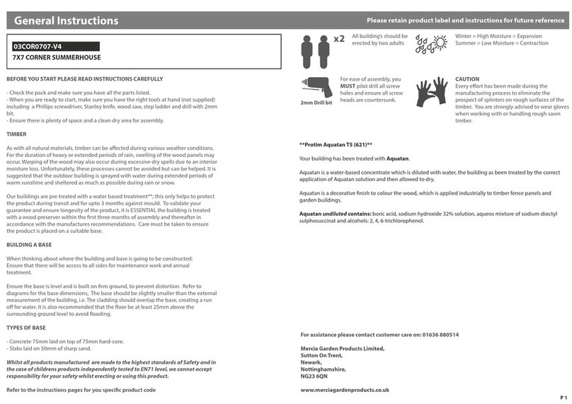
Mercia Garden Products 03COR0707-V4 General instructions
Mercia Garden Products

Mercia Garden Products 03COR0707-V4 General instructions

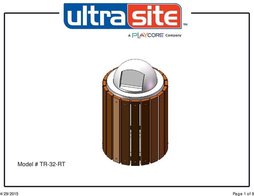
Playcore ultra site TR-32-RT manual

Playcore

Playcore ultra site TR-32-RT manual
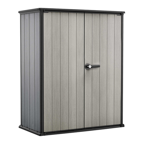
Keter DUOTECH HIGH-STORE+ 1403609 user manual
Keter

Keter DUOTECH HIGH-STORE+ 1403609 user manual

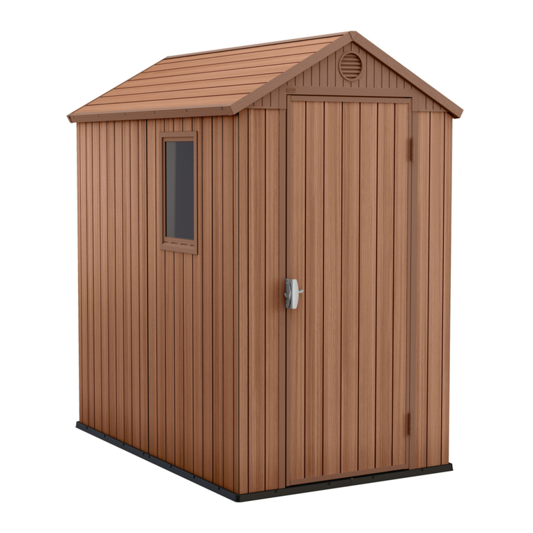
Keter DARWIN 4x6 user manual

Keter

Keter DARWIN 4x6 user manual

Handy Home Products OCOEE Assembly manual
Handy Home Products

Handy Home Products OCOEE Assembly manual

Biohort HighLine Series Assembly manual

Biohort

Biohort HighLine Series Assembly manual

Keter ARTISAN 97 user manual

Keter

Keter ARTISAN 97 user manual
Arrow Storage Products ED65SB Owner's manual & assembly instructions
Arrow Storage Products

Arrow Storage Products ED65SB Owner's manual & assembly instructions

Arrow Storage Products DKGA-A Owner's manual and assembly guide

Arrow Storage Products

Arrow Storage Products DKGA-A Owner's manual and assembly guide

SPACEMAKER EL64 Assembly instructions

SPACEMAKER

SPACEMAKER EL64 Assembly instructions
Palram Skylight Shed Assembly instructions
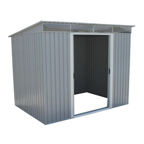
Palram

Palram Skylight Shed Assembly instructions

USP DuraMax 8 Ft x 8 Ft DuraPlus owner's manual
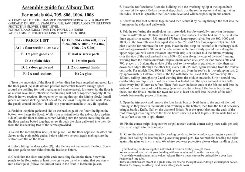
USP

USP DuraMax 8 Ft x 8 Ft DuraPlus owner's manual

Albany Dart 604 Assembly guide

Albany

Albany Dart 604 Assembly guide

Arrow Storage Products CLG1217CC Owner's manual & assembly guide

Arrow Storage Products

Arrow Storage Products CLG1217CC Owner's manual & assembly guide
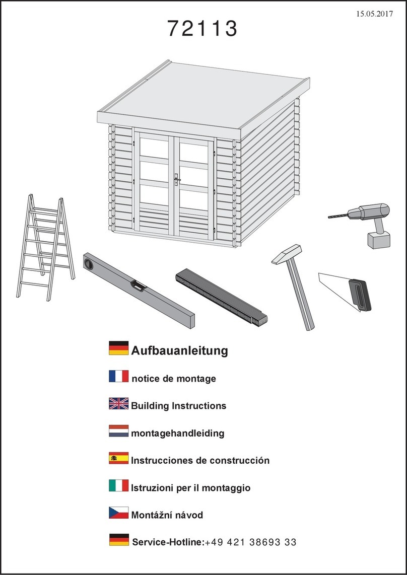
Karibu BASTRUP Building instructions

Karibu

Karibu BASTRUP Building instructions
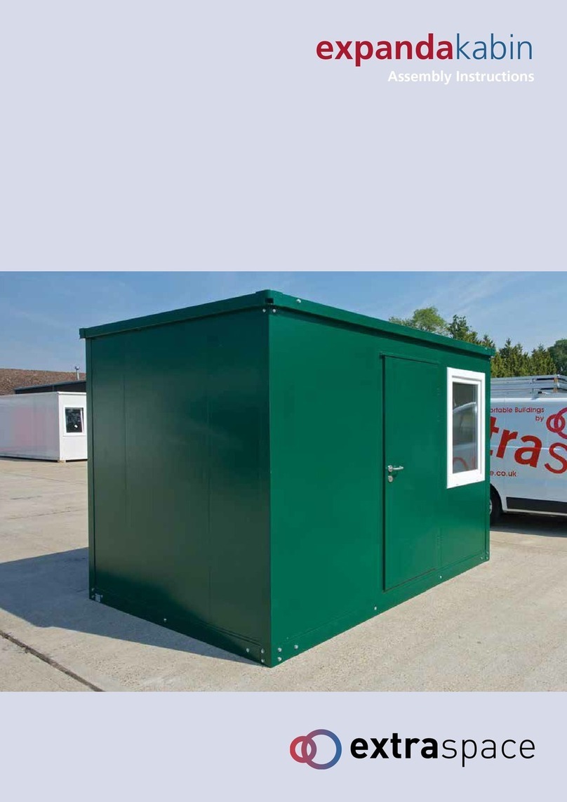
extraspace expandakabin Assembly instructions
extraspace

extraspace expandakabin Assembly instructions

Zipper Mowers ZI-GAB132AN user manual

Zipper Mowers

Zipper Mowers ZI-GAB132AN user manual

Mercia Garden Products 05DTOVAX0307DD-V1 manual

Mercia Garden Products

Mercia Garden Products 05DTOVAX0307DD-V1 manual

manuals.online logo
manuals.online logoBrands
  • About & Mission
  • Contact us
  • Privacy Policy
  • Terms and Conditions

Copyright 2025 Manuals.Online. All Rights Reserved.