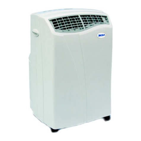
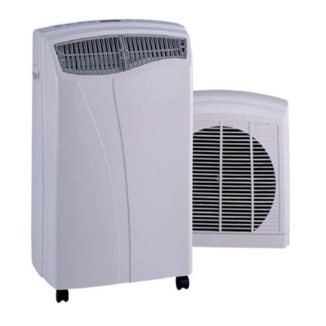
Desa SPV 12 EH User manual

Installation and operation manual
SPLIT AIR CONDITIONER
SPV 12 EH

TABLE OF CONTENS
Technical specification 2
Safety instructions 3
Components 5
Assembly instructions installation 6
Assembly instructions connection 10
Assembly instructions disconnection 14
Remote control 16
Display panel 17
Operation 18
Remote control notes 21
Maintenance 22
Maintenance before and after the season 23
Troubleshooting 24
1

2
TECHNICAL SPECIFICATION
Please note:
1. Information may vary for technical reasons
2. Measuring condition for above is based on regulation EN14511
Model SPV 12 EH
Power Supply V/Hz 220÷240 / 50Hz
Capacity (W) 3500
Power Consumption (W) 1220
Operating Current (A) 5,5
Cooling
EER (W/W) 2,87
Capacity (W) 3800
Power Consumption (W) 1180
Operating Current (A) 5,4
Heating
COP (W/W) 3,22
Airflow Volume m3/hr (Cooling/Heating) 520 / 560
Dehumidifying l/h 1,0
Refrigerant R407c (g) 850
Noise Level (db(A)) <43
Dimensions WxHxD (mm) 795x270x190
Packing WxHxD (mm) 860x320x400
Indoor Unit
Net/Gross Weight (kg) 11/16
Noise Level (db(A)) <53
Dimensions WxHxD (mm) 800x540x250
Packing WxHxD (mm) 888x590x344
Outdoor Unit
Net/Gross Weight (kg) 33/38
Suitable Area m3 80

3
SAFETY INSTRUCTIONS
!Please read carefully this Manual and Safety Instructions before operating the
appliance.
!Warnings and instructions under the heading “CAUTION / NOTES” warn against occurrence
of serious problems, or inform on how to optimize appliance operation. Reading and
observing such notes is critical for ensuring safe and efficient operation of the appliance.
!Symbols used in this Manual have the following meanings:
Formal
prohibition
Follow the
instructions
Ensure continuity
of earthing
Disconnect
power supply
!After you read this Manual please keep it at hand and protect from damage or loss.
1. Do not install the appliance in places
exposed to leakage of flammable
gases.
Gas leaking and accumulating around the
appliance may cause fire.
1. Electric installation is to be fitted with
differential current switch.
When the appliance is connected to
improperly protected installation it may
cause electric shock.
2. Electric installation is to be fitted with
differential current switch.
When the appliance is connected to improperly
protected installation it may cause electric
shock.
3. Make sure the condensate tube is
placed correctly, so that water can drain
out.
Improper placement of condensate tube
can result in flooding of premises and
dampening of furniture.
4. Make sure the housing of external module
is earthed.
Earthing conductors cannot be running along
gas pipes, water pipes, lighting arrester wire or
telephone earthing wire. Improper installation of
earthing conductor may result in electric shock.

4
Never expose your body to
cold air for a long time, as it
may have adverse effect to
your health.
Never introduce any objects or
body parts to internal and
external parts of the appliance.
Never use extension cords
or branch-joints to connect
the appliance to power
supply.
OPERATION INSTRUCTIONS
Protect power cord from
damage. Never switch the appliance on
or off by removing plug. Before switching on, always
check if the appliance is
correctly connected to power
supply.
DANGER!!!
CAUTION!!!
Never touch switches or
buttons with wet hands.
Never hang on the
appliance.
Never spray flammable products
(such as insecticides) near the
appliance.
Never place combustion devices
(generating fire) near from the
air-conditioner air outlet. Air-conditioner working range:
INSIDE OUTSIDE
COOLING
HEATING
O O
18 C - 43 C O O
9C - 43 C
O O
9C - 30 C O O
9C - 30 C
Air-conditioner is designed to operate within temperature range as in the table above! The appliance
can be operated in below zero temperatures after prior adaptation by authorized service center. For details
contact your authorized service center or retailer.

5
COMPONENTS
Indoor unit
Outdoor unit
Air outlet
Drainage hose
Connecting pipe and cable
Air inlet
Remote controller
Air filter
Air outlet
Vertical louver
Power plug
Horizontal louver
Indicate lamp & signal
receiving window
Emergency switch
Temperature sensor
Air intake grilles
Air inlet
Fig. 1

6
ASSEMBLY MANUAL
– INSTALLATION
1. Installation and connection.
A. External module
External module is to be installed in horizontal position
Option A Option B
Standing on
ground / platform
Wall-mounted
on support
(optional)
External module is to
be installed keeping
the minimum offsets
from walls, ceilings, etc.
0,6m
min
0,15m
min
0,6m
min
0,15m
min
0,6m
min
Note:
To ensure self-draining of
condensate (water restored from
air in air-conditioned premises) the
external module is to be mounted
below the Internal module see
Fig.6 “Basic Installation”. It is
however possible to mount the
modules as in Fig.7 “Optional
Installation”.
External
module
Pipeline
(optional)
Basic
installation
Optional
installation
External
module
Internal
module
Internal
module
Bracket spacing
Fig. 2 Fig. 3
Fig. 4
Fig. 5
Fig. 6
Fig. 7
A = 140 mm
B = 510 mm
C = 130 mm

7
Should you choose optional installation (Fig.7), with external module above the internal
module, bear in mind application of so-called “oil trap” Fig.8.
In case of any installation problems please contact authorized service center or retailer.
Should you decide for esthetics to lead the condensate tube upwards to external module
(see Fig.9), always apply condensate pump. For details contact authorized service center or
retailer.
Condensate
tube
Room 1 Room 2
Condensate
pump
Fig. 8
Fig. 9
oil trap

B. Installation of internal module using mounting plate
Internal module is to be mounted in horizontal position.
8
Indoor unit
Mounting plate
Mounting plate
Wall
)
Fixing on internal
module supports
ASSEMBLY
1. Hang upper part of
internal module on
mounting plate
2. Press the module till
its fixed
2 fixtures2 fixtures
Fig. 10
Fig. 11
Fig. 12

NOTE:
!Maximum distance between module installation locations is to be 5.0 m (Fig.13).
!Air-conditioner is to be so installed that flow and mixing of air and cause no
disturbance to inhabitants
!
9
Fig. 13
h(max) = 5,0 m
oil trap

The appliance is ready for DIY assembly a installation is already
filled with cooling agent.
10
ASSEMBLY INSTRUCTIONS
– CONNECTION
I. Appliance can be connected after unpacking
and installation in place. First unscrew and
remove the plastic cover.
II. Remove block stoppers
protecting cable
connections, both from
external module and
cables.
III. Attach and tighten cables of internal module
to connectors of stubs of external module.
NOTE!
1. Thinner (fluid) cable is to be attached to top
connection, and thicker (gas) cable to bottom
connector.
2. Use enclosed flat wrench sizes 22, 24, 27
and 30

11
3. While tightening screws always remember
holding screw with another flat wrench 22 and
27, i.e. tighten with 24 and 30 wrench and hold
with 22 and 24.
IV. Remove nuts from main valves.
Unscrew the valves completely (to the limit)
using Allen wrench.
In case of observing leaks of cooling agent,
close the valves and contact authorized service
center or retailer.

12
V. Connecting to electric installation.
Each cable is marked
with a digit
corresponding with
number on terminal
strip. Connect cables
to terminal strip
minding the numbers.
Having connected all
cables, attach
terminal strip to air-
conditioner housing.
VI. Having connected
cooling and electric
cables, replace the
cover protecting
interior against
weather conditions.

13
Properly connected external module.
Bundle excessive cable and place it behind
the modulej.
CAUTION!!!
The appliance is factor-filled with cooling agent.
Unscrewing the valves without connected cables can cause leak
of cooling agent.
Air-conditioner operation with insufficient level of cooling agent can cause damage to the appliance
TESTING THE AIR CONDITIONER
1. Connect the mains power
2. Locate the emergency power switch under the
cover of the indoor unit and turn the power on
3. The unit will sound once, the indoor fan will start
and all the lights on the unit will illuminate
4. The unit will work in AUTO mode.
After testing the unit, the emergency power switch
should only be used when the remote control is
lost or defective

14
ASSEMBLY INSTRUCTIONS
DISCONNECTION
I. Start air-conditioner in cooling mode. Turn off
fluid valve during appliance operation (valve
connected to thinner cable).
II. After 60 seconds turn off gas valve (valve
connected to thicker cable). Then immediately
switch off the appliance using START/STOP
button on remote control.
CAUTION!!! Compressor operation with closed
fluid valve that is longer than 60 seconds will
cause damage to appliance.
III. Turn on cooling agent valves. Always
remember to do it using two wrenches,
otherwise you may damage the valve
IV. Unscrew the cable connector.

15
Unscrew control cables from terminal strip.
V. Secure all openings with stoppers to protect
appliance against dust, sand and thread damage
CAUTION!!!
During each disassembly a minor leak of cooling agent shall occur.
The appliance is designed for 5 disassemblies. After that cooling agent is
to be refilled or replaced. Replacement or refilling shall be performed only
by specialized service center

16
REMOTE CONTROL
The air conditioner unit should be operated and set using
the remote control provided. Each time a button is pressed
the unit will sound to confirm the signal has been received
1. Set Temperature display
2. Clock display
3. Mode(function) display
4. Mode(function) button
5. Timer button
6. Hour setting for timer/clock
7. Airflow direction (Swing) button
8. Power button
9. Fan speed display
10. Airflow direction display
11. Sleep/Timer display
12. Temperature increase
13. Fan Speed
14. Sleep button (on/off)
15. Temperature decrease
16. Minute setting for timer/clock
1
234
5
67
8
9
1
2
3
4
5
6
7
8
9
10
11
12
13
14
15
16
Remote Control Indications
1. Auto Function Selected
2. Cooling Function Selected
3. De-humidifying Function Selected
4. Fan Function Selected
5. Heating Function Selected
6. Temperature Indicator (press ‘Up’/’Down’ to show
the set temperature – the temperature range is
o o
18 C – 30 C)
7. Fan Speed Indicator (Auto, High, Medium, Low)
8. Airflow Directional Indicator
9. Timer Indicator

17
DISPLAY PANEL
A. Auto Mode function
B. Cooling Function
C. In Operation
The indicator will be light when the air conditioner works.
D. Timer Function: The indicator will be light when the air conditioner is on
the TIMER mode.
E. Temperature display
The “88” location will show the room temperature when the air conditioner
works; It will show the left time under the timer-on setting; It will show the fault
number when the air conditioner is fault.
F. Required Temperature
The indicator lights and “88” location will show the room temperature.
G. Setting Temperature
The “88” location will show the setting temperature when the indicator
is flash.
H. Heating Function
I. De-humidifying Function
J. Status Bar

18
OPERATION
AUTO Function
When using the emergency power switch, the unit will operate in 'Auto' function
according to the room temperatures below and the louvers will oscillate in the
'Standard' cycle
Please Note Using the emergency power switch will cancel the 'Timer'/'Sleep'
functions
Change Function
To change the function, press the 'Mode' button (4) repeatedly, until the desired
function is reached
Auto Cool Heat De-humidify
To change the fan speed, press the 'Fan' button (13) repeatedly, until the desired
function is reached
AUTO HIGH MEDIUM LOW
o
Please Note When the Required Temperature is less than 18 C or greater than
o
30 C, 'CONT' will be displayed on the remote control and the unit will operate
continuously.
o
!Cooling function if the room temperature is greater than 26 C
o o
!De-humidifying Function if the room temperature is between 21 C and 26 C
o
!Heating Function if the room temperature is less than 21 C
!The required room temperature is adjusted using the 'Up' and 'Down'
arrows (12&15)
!The direction of the airflow can be adjusted using the 'Swing' button (7)
!The timer can be set/cancelled by pressing the 'Timer' button (5)
!The sleep mode can be set/cancelled by pressing the 'Sleep' button (14)
!The current time can be set using the 'Hour' (6) and 'Min' (16) buttons
!The unit can be switched on or off by using the 'On/Off' button (8)

19
Setting the Clock
The clock is set on the remote control by pressing the 'Hour' and 'Min' buttons until
the accurate time is reached
Timer Function
Please Note - In order for the timer to work, the clock must first be set on the remote
control
The timer can be set to control when the unit will start functioning within 24 hours of
the current time
Sleep Function
The air conditioner unit is also equipped with a Sleep function. This enables the unit
to switch off after 1, 2, 3, 5, 7 or 10 hours
!Set the clock to the correct time, following the method above
!Press the 'Timer' button so 'HOUR' is displayed
!Press the 'Hour'/'Min' buttons until the desired time before the unit switches on is
displayed on the remote control
!The unit will automatically check the temperature 1 hour before running time and
choose the appropriate Cool/Heat function
!Pressing the 'Timer' button again will cancel the timer function
!Press the 'Sleep' button so the moon logo is displayed on the remote control
!Press the 'Up' arrow to set the required time
!Pressing the 'Sleep' button again will cancel the function
Other manuals for SPV 12 EH
1
Other Desa Air Conditioner manuals
Popular Air Conditioner manuals by other brands

Friedrich
Friedrich MR09C1F installation manual

LG
LG AHU EEV KIT installation manual

Panasonic
Panasonic CS-YE9WKU1 operating instructions

Armcor
Armcor XCC Installation and operation manual

Soleus Air
Soleus Air KC-45H OPERATING AND INSTALLATION Manual

Technibel
Technibel MCAF92R5TA Technical data & service manual